EP0446593A1 - Production of oxygen-lean argon from air - Google Patents
Production of oxygen-lean argon from air Download PDFInfo
- Publication number
- EP0446593A1 EP0446593A1 EP91101288A EP91101288A EP0446593A1 EP 0446593 A1 EP0446593 A1 EP 0446593A1 EP 91101288 A EP91101288 A EP 91101288A EP 91101288 A EP91101288 A EP 91101288A EP 0446593 A1 EP0446593 A1 EP 0446593A1
- Authority
- EP
- European Patent Office
- Prior art keywords
- argon
- column
- crude
- oxygen
- liquid oxygen
- Prior art date
- Legal status (The legal status is an assumption and is not a legal conclusion. Google has not performed a legal analysis and makes no representation as to the accuracy of the status listed.)
- Granted
Links
- XKRFYHLGVUSROY-UHFFFAOYSA-N Argon Chemical compound [Ar] XKRFYHLGVUSROY-UHFFFAOYSA-N 0.000 title claims abstract description 669
- 229910052786 argon Inorganic materials 0.000 title claims abstract description 336
- 238000004519 manufacturing process Methods 0.000 title claims abstract description 17
- MYMOFIZGZYHOMD-UHFFFAOYSA-N Dioxygen Chemical compound O=O MYMOFIZGZYHOMD-UHFFFAOYSA-N 0.000 claims abstract description 80
- 239000001301 oxygen Substances 0.000 claims abstract description 76
- 229910052760 oxygen Inorganic materials 0.000 claims abstract description 76
- QVGXLLKOCUKJST-UHFFFAOYSA-N atomic oxygen Chemical compound [O] QVGXLLKOCUKJST-UHFFFAOYSA-N 0.000 claims abstract description 75
- 238000011084 recovery Methods 0.000 claims abstract description 62
- 238000012856 packing Methods 0.000 claims abstract description 46
- 238000000034 method Methods 0.000 claims abstract description 43
- 238000000926 separation method Methods 0.000 claims abstract description 24
- 239000007791 liquid phase Substances 0.000 claims abstract description 16
- 239000012808 vapor phase Substances 0.000 claims abstract description 16
- 230000006872 improvement Effects 0.000 claims abstract description 12
- 238000004821 distillation Methods 0.000 claims description 60
- 230000008569 process Effects 0.000 claims description 39
- 238000010992 reflux Methods 0.000 claims description 14
- 238000005057 refrigeration Methods 0.000 claims description 10
- VVTSZOCINPYFDP-UHFFFAOYSA-N [O].[Ar] Chemical compound [O].[Ar] VVTSZOCINPYFDP-UHFFFAOYSA-N 0.000 claims description 5
- 230000009467 reduction Effects 0.000 claims description 4
- 230000003247 decreasing effect Effects 0.000 abstract description 6
- -1 <0.5% oxygen Chemical compound 0.000 abstract 1
- IJGRMHOSHXDMSA-UHFFFAOYSA-N Atomic nitrogen Chemical compound N#N IJGRMHOSHXDMSA-UHFFFAOYSA-N 0.000 description 38
- 239000000047 product Substances 0.000 description 28
- 229910052757 nitrogen Inorganic materials 0.000 description 19
- 239000007788 liquid Substances 0.000 description 18
- 238000004088 simulation Methods 0.000 description 10
- 230000007423 decrease Effects 0.000 description 8
- 230000000694 effects Effects 0.000 description 8
- 239000012530 fluid Substances 0.000 description 8
- 238000009835 boiling Methods 0.000 description 6
- 239000002699 waste material Substances 0.000 description 5
- CURLTUGMZLYLDI-UHFFFAOYSA-N Carbon dioxide Chemical compound O=C=O CURLTUGMZLYLDI-UHFFFAOYSA-N 0.000 description 4
- 150000001485 argon Chemical class 0.000 description 3
- 238000005194 fractionation Methods 0.000 description 3
- 239000007789 gas Substances 0.000 description 3
- UFHFLCQGNIYNRP-UHFFFAOYSA-N Hydrogen Chemical compound [H][H] UFHFLCQGNIYNRP-UHFFFAOYSA-N 0.000 description 2
- 230000002411 adverse Effects 0.000 description 2
- 229910002092 carbon dioxide Inorganic materials 0.000 description 2
- 238000010586 diagram Methods 0.000 description 2
- 239000001257 hydrogen Substances 0.000 description 2
- 229910052739 hydrogen Inorganic materials 0.000 description 2
- 238000002156 mixing Methods 0.000 description 2
- 238000005457 optimization Methods 0.000 description 2
- XLYOFNOQVPJJNP-UHFFFAOYSA-N water Substances O XLYOFNOQVPJJNP-UHFFFAOYSA-N 0.000 description 2
- 238000010521 absorption reaction Methods 0.000 description 1
- 239000003463 adsorbent Substances 0.000 description 1
- 230000009286 beneficial effect Effects 0.000 description 1
- 238000004364 calculation method Methods 0.000 description 1
- 239000001569 carbon dioxide Substances 0.000 description 1
- 230000003197 catalytic effect Effects 0.000 description 1
- 238000006555 catalytic reaction Methods 0.000 description 1
- 230000008859 change Effects 0.000 description 1
- 238000003889 chemical engineering Methods 0.000 description 1
- 230000000052 comparative effect Effects 0.000 description 1
- 230000006835 compression Effects 0.000 description 1
- 238000007906 compression Methods 0.000 description 1
- 238000009833 condensation Methods 0.000 description 1
- 230000005494 condensation Effects 0.000 description 1
- 239000000498 cooling water Substances 0.000 description 1
- 239000012043 crude product Substances 0.000 description 1
- 238000011143 downstream manufacturing Methods 0.000 description 1
- 238000005265 energy consumption Methods 0.000 description 1
- 238000001704 evaporation Methods 0.000 description 1
- 239000012467 final product Substances 0.000 description 1
- 230000005484 gravity Effects 0.000 description 1
- 230000010354 integration Effects 0.000 description 1
- 239000012263 liquid product Substances 0.000 description 1
- VUZPPFZMUPKLLV-UHFFFAOYSA-N methane;hydrate Chemical compound C.O VUZPPFZMUPKLLV-UHFFFAOYSA-N 0.000 description 1
- 150000002926 oxygen Chemical class 0.000 description 1
- 238000010926 purge Methods 0.000 description 1
- 238000000746 purification Methods 0.000 description 1
- 230000000630 rising effect Effects 0.000 description 1
- 238000001179 sorption measurement Methods 0.000 description 1
- 239000000126 substance Substances 0.000 description 1
- 238000009834 vaporization Methods 0.000 description 1
- 230000008016 vaporization Effects 0.000 description 1
Images




Classifications
-
- F—MECHANICAL ENGINEERING; LIGHTING; HEATING; WEAPONS; BLASTING
- F25—REFRIGERATION OR COOLING; COMBINED HEATING AND REFRIGERATION SYSTEMS; HEAT PUMP SYSTEMS; MANUFACTURE OR STORAGE OF ICE; LIQUEFACTION SOLIDIFICATION OF GASES
- F25J—LIQUEFACTION, SOLIDIFICATION OR SEPARATION OF GASES OR GASEOUS OR LIQUEFIED GASEOUS MIXTURES BY PRESSURE AND COLD TREATMENT OR BY BRINGING THEM INTO THE SUPERCRITICAL STATE
- F25J3/00—Processes or apparatus for separating the constituents of gaseous or liquefied gaseous mixtures involving the use of liquefaction or solidification
- F25J3/02—Processes or apparatus for separating the constituents of gaseous or liquefied gaseous mixtures involving the use of liquefaction or solidification by rectification, i.e. by continuous interchange of heat and material between a vapour stream and a liquid stream
- F25J3/04—Processes or apparatus for separating the constituents of gaseous or liquefied gaseous mixtures involving the use of liquefaction or solidification by rectification, i.e. by continuous interchange of heat and material between a vapour stream and a liquid stream for air
- F25J3/04763—Start-up or control of the process; Details of the apparatus used
- F25J3/04866—Construction and layout of air fractionation equipments, e.g. valves, machines
- F25J3/04896—Details of columns, e.g. internals, inlet/outlet devices
- F25J3/04915—Combinations of different material exchange elements, e.g. within different columns
- F25J3/04921—Combinations of different material exchange elements, e.g. within different columns within the same column
-
- C—CHEMISTRY; METALLURGY
- C01—INORGANIC CHEMISTRY
- C01B—NON-METALLIC ELEMENTS; COMPOUNDS THEREOF; METALLOIDS OR COMPOUNDS THEREOF NOT COVERED BY SUBCLASS C01C
- C01B23/00—Noble gases; Compounds thereof
-
- F—MECHANICAL ENGINEERING; LIGHTING; HEATING; WEAPONS; BLASTING
- F25—REFRIGERATION OR COOLING; COMBINED HEATING AND REFRIGERATION SYSTEMS; HEAT PUMP SYSTEMS; MANUFACTURE OR STORAGE OF ICE; LIQUEFACTION SOLIDIFICATION OF GASES
- F25J—LIQUEFACTION, SOLIDIFICATION OR SEPARATION OF GASES OR GASEOUS OR LIQUEFIED GASEOUS MIXTURES BY PRESSURE AND COLD TREATMENT OR BY BRINGING THEM INTO THE SUPERCRITICAL STATE
- F25J3/00—Processes or apparatus for separating the constituents of gaseous or liquefied gaseous mixtures involving the use of liquefaction or solidification
- F25J3/02—Processes or apparatus for separating the constituents of gaseous or liquefied gaseous mixtures involving the use of liquefaction or solidification by rectification, i.e. by continuous interchange of heat and material between a vapour stream and a liquid stream
- F25J3/04—Processes or apparatus for separating the constituents of gaseous or liquefied gaseous mixtures involving the use of liquefaction or solidification by rectification, i.e. by continuous interchange of heat and material between a vapour stream and a liquid stream for air
- F25J3/04248—Generation of cold for compensating heat leaks or liquid production, e.g. by Joule-Thompson expansion
- F25J3/04284—Generation of cold for compensating heat leaks or liquid production, e.g. by Joule-Thompson expansion using internal refrigeration by open-loop gas work expansion, e.g. of intermediate or oxygen enriched (waste-)streams
- F25J3/0429—Generation of cold for compensating heat leaks or liquid production, e.g. by Joule-Thompson expansion using internal refrigeration by open-loop gas work expansion, e.g. of intermediate or oxygen enriched (waste-)streams of feed air, e.g. used as waste or product air or expanded into an auxiliary column
- F25J3/04303—Lachmann expansion, i.e. expanded into oxygen producing or low pressure column
-
- F—MECHANICAL ENGINEERING; LIGHTING; HEATING; WEAPONS; BLASTING
- F25—REFRIGERATION OR COOLING; COMBINED HEATING AND REFRIGERATION SYSTEMS; HEAT PUMP SYSTEMS; MANUFACTURE OR STORAGE OF ICE; LIQUEFACTION SOLIDIFICATION OF GASES
- F25J—LIQUEFACTION, SOLIDIFICATION OR SEPARATION OF GASES OR GASEOUS OR LIQUEFIED GASEOUS MIXTURES BY PRESSURE AND COLD TREATMENT OR BY BRINGING THEM INTO THE SUPERCRITICAL STATE
- F25J3/00—Processes or apparatus for separating the constituents of gaseous or liquefied gaseous mixtures involving the use of liquefaction or solidification
- F25J3/02—Processes or apparatus for separating the constituents of gaseous or liquefied gaseous mixtures involving the use of liquefaction or solidification by rectification, i.e. by continuous interchange of heat and material between a vapour stream and a liquid stream
- F25J3/04—Processes or apparatus for separating the constituents of gaseous or liquefied gaseous mixtures involving the use of liquefaction or solidification by rectification, i.e. by continuous interchange of heat and material between a vapour stream and a liquid stream for air
- F25J3/04248—Generation of cold for compensating heat leaks or liquid production, e.g. by Joule-Thompson expansion
- F25J3/04333—Generation of cold for compensating heat leaks or liquid production, e.g. by Joule-Thompson expansion using quasi-closed loop internal vapor compression refrigeration cycles, e.g. of intermediate or oxygen enriched (waste-)streams
- F25J3/04369—Generation of cold for compensating heat leaks or liquid production, e.g. by Joule-Thompson expansion using quasi-closed loop internal vapor compression refrigeration cycles, e.g. of intermediate or oxygen enriched (waste-)streams of argon or argon enriched stream
-
- F—MECHANICAL ENGINEERING; LIGHTING; HEATING; WEAPONS; BLASTING
- F25—REFRIGERATION OR COOLING; COMBINED HEATING AND REFRIGERATION SYSTEMS; HEAT PUMP SYSTEMS; MANUFACTURE OR STORAGE OF ICE; LIQUEFACTION SOLIDIFICATION OF GASES
- F25J—LIQUEFACTION, SOLIDIFICATION OR SEPARATION OF GASES OR GASEOUS OR LIQUEFIED GASEOUS MIXTURES BY PRESSURE AND COLD TREATMENT OR BY BRINGING THEM INTO THE SUPERCRITICAL STATE
- F25J3/00—Processes or apparatus for separating the constituents of gaseous or liquefied gaseous mixtures involving the use of liquefaction or solidification
- F25J3/02—Processes or apparatus for separating the constituents of gaseous or liquefied gaseous mixtures involving the use of liquefaction or solidification by rectification, i.e. by continuous interchange of heat and material between a vapour stream and a liquid stream
- F25J3/04—Processes or apparatus for separating the constituents of gaseous or liquefied gaseous mixtures involving the use of liquefaction or solidification by rectification, i.e. by continuous interchange of heat and material between a vapour stream and a liquid stream for air
- F25J3/04406—Processes or apparatus for separating the constituents of gaseous or liquefied gaseous mixtures involving the use of liquefaction or solidification by rectification, i.e. by continuous interchange of heat and material between a vapour stream and a liquid stream for air using a dual pressure main column system
- F25J3/04412—Processes or apparatus for separating the constituents of gaseous or liquefied gaseous mixtures involving the use of liquefaction or solidification by rectification, i.e. by continuous interchange of heat and material between a vapour stream and a liquid stream for air using a dual pressure main column system in a classical double column flowsheet, i.e. with thermal coupling by a main reboiler-condenser in the bottom of low pressure respectively top of high pressure column
-
- F—MECHANICAL ENGINEERING; LIGHTING; HEATING; WEAPONS; BLASTING
- F25—REFRIGERATION OR COOLING; COMBINED HEATING AND REFRIGERATION SYSTEMS; HEAT PUMP SYSTEMS; MANUFACTURE OR STORAGE OF ICE; LIQUEFACTION SOLIDIFICATION OF GASES
- F25J—LIQUEFACTION, SOLIDIFICATION OR SEPARATION OF GASES OR GASEOUS OR LIQUEFIED GASEOUS MIXTURES BY PRESSURE AND COLD TREATMENT OR BY BRINGING THEM INTO THE SUPERCRITICAL STATE
- F25J3/00—Processes or apparatus for separating the constituents of gaseous or liquefied gaseous mixtures involving the use of liquefaction or solidification
- F25J3/02—Processes or apparatus for separating the constituents of gaseous or liquefied gaseous mixtures involving the use of liquefaction or solidification by rectification, i.e. by continuous interchange of heat and material between a vapour stream and a liquid stream
- F25J3/04—Processes or apparatus for separating the constituents of gaseous or liquefied gaseous mixtures involving the use of liquefaction or solidification by rectification, i.e. by continuous interchange of heat and material between a vapour stream and a liquid stream for air
- F25J3/04642—Recovering noble gases from air
- F25J3/04648—Recovering noble gases from air argon
- F25J3/04654—Producing crude argon in a crude argon column
- F25J3/04666—Producing crude argon in a crude argon column as a parallel working rectification column of the low pressure column in a dual pressure main column system
- F25J3/04672—Producing crude argon in a crude argon column as a parallel working rectification column of the low pressure column in a dual pressure main column system having a top condenser
- F25J3/04678—Producing crude argon in a crude argon column as a parallel working rectification column of the low pressure column in a dual pressure main column system having a top condenser cooled by oxygen enriched liquid from high pressure column bottoms
-
- F—MECHANICAL ENGINEERING; LIGHTING; HEATING; WEAPONS; BLASTING
- F25—REFRIGERATION OR COOLING; COMBINED HEATING AND REFRIGERATION SYSTEMS; HEAT PUMP SYSTEMS; MANUFACTURE OR STORAGE OF ICE; LIQUEFACTION SOLIDIFICATION OF GASES
- F25J—LIQUEFACTION, SOLIDIFICATION OR SEPARATION OF GASES OR GASEOUS OR LIQUEFIED GASEOUS MIXTURES BY PRESSURE AND COLD TREATMENT OR BY BRINGING THEM INTO THE SUPERCRITICAL STATE
- F25J3/00—Processes or apparatus for separating the constituents of gaseous or liquefied gaseous mixtures involving the use of liquefaction or solidification
- F25J3/02—Processes or apparatus for separating the constituents of gaseous or liquefied gaseous mixtures involving the use of liquefaction or solidification by rectification, i.e. by continuous interchange of heat and material between a vapour stream and a liquid stream
- F25J3/04—Processes or apparatus for separating the constituents of gaseous or liquefied gaseous mixtures involving the use of liquefaction or solidification by rectification, i.e. by continuous interchange of heat and material between a vapour stream and a liquid stream for air
- F25J3/04642—Recovering noble gases from air
- F25J3/04648—Recovering noble gases from air argon
- F25J3/04654—Producing crude argon in a crude argon column
- F25J3/04709—Producing crude argon in a crude argon column as an auxiliary column system in at least a dual pressure main column system
-
- F—MECHANICAL ENGINEERING; LIGHTING; HEATING; WEAPONS; BLASTING
- F25—REFRIGERATION OR COOLING; COMBINED HEATING AND REFRIGERATION SYSTEMS; HEAT PUMP SYSTEMS; MANUFACTURE OR STORAGE OF ICE; LIQUEFACTION SOLIDIFICATION OF GASES
- F25J—LIQUEFACTION, SOLIDIFICATION OR SEPARATION OF GASES OR GASEOUS OR LIQUEFIED GASEOUS MIXTURES BY PRESSURE AND COLD TREATMENT OR BY BRINGING THEM INTO THE SUPERCRITICAL STATE
- F25J2205/00—Processes or apparatus using other separation and/or other processing means
- F25J2205/02—Processes or apparatus using other separation and/or other processing means using simple phase separation in a vessel or drum
-
- F—MECHANICAL ENGINEERING; LIGHTING; HEATING; WEAPONS; BLASTING
- F25—REFRIGERATION OR COOLING; COMBINED HEATING AND REFRIGERATION SYSTEMS; HEAT PUMP SYSTEMS; MANUFACTURE OR STORAGE OF ICE; LIQUEFACTION SOLIDIFICATION OF GASES
- F25J—LIQUEFACTION, SOLIDIFICATION OR SEPARATION OF GASES OR GASEOUS OR LIQUEFIED GASEOUS MIXTURES BY PRESSURE AND COLD TREATMENT OR BY BRINGING THEM INTO THE SUPERCRITICAL STATE
- F25J2230/00—Processes or apparatus involving steps for increasing the pressure of gaseous process streams
- F25J2230/58—Processes or apparatus involving steps for increasing the pressure of gaseous process streams the fluid being argon or crude argon
-
- F—MECHANICAL ENGINEERING; LIGHTING; HEATING; WEAPONS; BLASTING
- F25—REFRIGERATION OR COOLING; COMBINED HEATING AND REFRIGERATION SYSTEMS; HEAT PUMP SYSTEMS; MANUFACTURE OR STORAGE OF ICE; LIQUEFACTION SOLIDIFICATION OF GASES
- F25J—LIQUEFACTION, SOLIDIFICATION OR SEPARATION OF GASES OR GASEOUS OR LIQUEFIED GASEOUS MIXTURES BY PRESSURE AND COLD TREATMENT OR BY BRINGING THEM INTO THE SUPERCRITICAL STATE
- F25J2240/00—Processes or apparatus involving steps for expanding of process streams
- F25J2240/40—Expansion without extracting work, i.e. isenthalpic throttling, e.g. JT valve, regulating valve or venturi, or isentropic nozzle, e.g. Laval
-
- F—MECHANICAL ENGINEERING; LIGHTING; HEATING; WEAPONS; BLASTING
- F25—REFRIGERATION OR COOLING; COMBINED HEATING AND REFRIGERATION SYSTEMS; HEAT PUMP SYSTEMS; MANUFACTURE OR STORAGE OF ICE; LIQUEFACTION SOLIDIFICATION OF GASES
- F25J—LIQUEFACTION, SOLIDIFICATION OR SEPARATION OF GASES OR GASEOUS OR LIQUEFIED GASEOUS MIXTURES BY PRESSURE AND COLD TREATMENT OR BY BRINGING THEM INTO THE SUPERCRITICAL STATE
- F25J2290/00—Other details not covered by groups F25J2200/00 - F25J2280/00
- F25J2290/10—Mathematical formulae, modeling, plot or curves; Design methods
-
- Y—GENERAL TAGGING OF NEW TECHNOLOGICAL DEVELOPMENTS; GENERAL TAGGING OF CROSS-SECTIONAL TECHNOLOGIES SPANNING OVER SEVERAL SECTIONS OF THE IPC; TECHNICAL SUBJECTS COVERED BY FORMER USPC CROSS-REFERENCE ART COLLECTIONS [XRACs] AND DIGESTS
- Y10—TECHNICAL SUBJECTS COVERED BY FORMER USPC
- Y10S—TECHNICAL SUBJECTS COVERED BY FORMER USPC CROSS-REFERENCE ART COLLECTIONS [XRACs] AND DIGESTS
- Y10S62/00—Refrigeration
- Y10S62/902—Apparatus
- Y10S62/905—Column
- Y10S62/906—Packing
-
- Y—GENERAL TAGGING OF NEW TECHNOLOGICAL DEVELOPMENTS; GENERAL TAGGING OF CROSS-SECTIONAL TECHNOLOGIES SPANNING OVER SEVERAL SECTIONS OF THE IPC; TECHNICAL SUBJECTS COVERED BY FORMER USPC CROSS-REFERENCE ART COLLECTIONS [XRACs] AND DIGESTS
- Y10—TECHNICAL SUBJECTS COVERED BY FORMER USPC
- Y10S—TECHNICAL SUBJECTS COVERED BY FORMER USPC CROSS-REFERENCE ART COLLECTIONS [XRACs] AND DIGESTS
- Y10S62/00—Refrigeration
- Y10S62/923—Inert gas
- Y10S62/924—Argon
-
- Y—GENERAL TAGGING OF NEW TECHNOLOGICAL DEVELOPMENTS; GENERAL TAGGING OF CROSS-SECTIONAL TECHNOLOGIES SPANNING OVER SEVERAL SECTIONS OF THE IPC; TECHNICAL SUBJECTS COVERED BY FORMER USPC CROSS-REFERENCE ART COLLECTIONS [XRACs] AND DIGESTS
- Y10—TECHNICAL SUBJECTS COVERED BY FORMER USPC
- Y10S—TECHNICAL SUBJECTS COVERED BY FORMER USPC CROSS-REFERENCE ART COLLECTIONS [XRACs] AND DIGESTS
- Y10S62/00—Refrigeration
- Y10S62/939—Partial feed stream expansion, air
Definitions
- the present invention relates to a process for the separation of air into its constitutent components by means of cryogenic distillation. More specifically, the present invention relates, to a process for the production of crude argon directly from the cold box of the cryogenic distillation unit.
- Argon is recoverable from sources such as air and NH3 purge gas.
- Most argon is produced as a crude product from cryogenic air separation units because it is comparatively economical.
- the typical concentration of oxygen in crude argon produced by cryogenic air separation unit is 2-5%, whereas most of the argon uses require nearly oxygen-free argon. This leads to expensive downstream processing of crude argon to reduce its oxygen content. It is desirable to directly produce an argon stream from a cryogenic air separation unit in high recoveries with decreased oxygen content so that either it could be directly used by the users or minimize the processing required to further purify it.
- the other fraction is vaporized in the overhead reboiler/condenser of argon sidearm column and is fed to the low pressure column a few trays below where the crude liquid oxygen is fed in.
- the low pressure column produces gaseous nitrogen product, oxygen product and a waste nitrogen stream.
- An argon-rich (7-12% argon) vapor stream is withdrawn from the low pressure column, many trays below the vaporized crude oxygen feed point and is fed into the bottom of crude argon distillation column with a reboiler/condenser at the top.
- the nitrogen concentration of this argon-rich stream is typically very low (0.01 to 0.1% nitrogen).
- the argon available from the air is drawn as crude argon containing 2-5% oxygen from the top of the argon sidearm column.
- argon is a valuable product, its recovery is often maximized by optimizing the number of theoretical stages in each section of the low pressure and argon sidearm columns and also the flowrates of various streams.
- the optimization of these theoretical stages goes hand-in-hand with the fact that since early 1930's sieve trays have been the trays of choice for cryogenic air separation unit. These sieve trays have certain contact efficiency and pressure drop per tray.
- the ratio of these parameters is the pressure drop ( ⁇ P) per theoretical stage (or equilibrium stage).
- the total pressure drop available for operation of the argon sidearm column limits the number of theoretical stages which can be used in it.
- the relative volatility of the argon with respect to oxygen ( ⁇ ) is about 1.5 at the bottom of argon sidearm column but is only about 1.1 at the top of this column. This low value of ⁇ at the top of the column makes it difficult to produce crude argon with low concentrations of oxygen in high recoveries.
- This oxygen-containing argon (crude argon) is then further purified in a catalytic reaction unit.
- crude argon is mixed with hydrogen and passed through a catalytic unit to react the oxygen to form water.
- the present invention is an improvement to a process for the separation of air by cryogenic distillation to produce a crude argon product.
- the separation is carried out in a multiple distillation column system containing a high pressure column, a low pressure column and an argon sidearm column; a crude argon product is produced at the top of the argon sidearm column; at least a portion of crude liquid oxygen produced at the bottom of the high pressure column is fed to a reboiler/condenser located at the top of the argon sidearm column to provide refrigeration for condensing at least a portion of the crude argon thereby providing reflux for the argon sidearm column; a gaseous argon-oxygen containing side stream is removed from an intermediate location of the low pressure column and fed to the bottom of the argon sidearm column for rectification; and the argon sidearm column a liquid phase and a vapor phase are intimately contacted to effectuate mass transfer to and from the liquid and vapor phases.
- the improvement for the production of low oxygen content argon having an oxygen concentration of less than or equal to 0.5 mol percent directly from the argon side arm column while maximizing argon recovery comprises three steps.
- First, an argon sidearm column is used which has an effective number of theoretical stages so as to produce a particular crude argon product purity without sacrificing argon recovery.
- Second, the crude liquid oxygen is fed from the bottom of the high pressure column to the reboiler condenser located in the top of the argon side arm column at a rate in the range from about 1.04 to about 1.36 times the theoretical minimum flow of crude liquid oxygen necessary to completely vaporize that minimum flow of crude liquid oxygen to its dew point.
- the argon sidearm column is operated so as to achieve a pressure at the top of the argon side arm column such that the flow of crude liquid oxygen to the reboiler/condenser located in the top of the side arm column falls within the range from about 1.04 to about 1.36 times the theoretical minimum flow of crude liquid oxygen necessary to completely vaporize that minimum flow of crude liquid oxygen to its dew point.
- This third step can be accomplished in two ways.
- the preferred method is to effectuate the intimate contact between the vapor and liquid phases in the argon side arm column by use of a combination of conventional sieve trays and low pressure drop, structured packing so that pressure drop across the combination results in a pressure at the top of the argon side arm column such that the flow of crude liquid oxygen to the reboiler/condenser located in the top of the side arm column falls within the range from about 1.04 to about 1.36 times the theoretical minimum flow of crude liquid oxygen necessary to completely vaporize that minimum flow of crude liquid oxygen to its dew point.
- An alternative method is to effectuate the intimate contact between the vapor and liquid phases in the argon side arm column by use of low pressure, structured packing and reducing the pressure of the argon/oxygen side stream fed to the argon sidearm column so that the combination of the pressure drop across the low pressure, structured packing and the reduction of pressure of the argon/oxygen side stream fed to the argon sidearm column result in a pressure at the top of the argon side arm column such that the flow of crude liquid oxygen to the reboiler/condenser located in the top of the side arm column falls within the range from about 1.04 to about 1.36 times the theoretical minimum flow of crude liquid oxygen necessary to completely vaporize that minimum flow of crude liquid oxygen to its dew point.
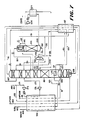
- Figure 1 is a schematic diagram of a cryogenic air separation process for the production of a crude argon product.
- FIG 2 is a schematic diagram of the cryogenic air separation process shown in Figure 1 with the packing section of the argon sidearm column highlighted.
- Figure 3 is a plot showing the effect of the pressure at the top of the argon sidearm column on argon recovery.
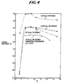
- Figure 4 is a plot showing the effect of crude liquid oxygen flow to the reboiler/condenser at the top of the argon sidearm column on argon recovery.
- Figure 5 is a plot of the effect on the number of theoretical stages in the argon sidearm column on argon purity.
- Figure 6 is a schematic of an alternate process for the production of low oxygen content argon.
- Figure 7 is a schematic of a variation on the alternate process for the production of low oxygen content argon shown in Figure 6.
- the present invention is an improvement to a process for the cryogenic distillation of air to produce nitrogen, oxygen and argon products.
- these processes use a cryogenic distillation system which comprise three distillation columns: a high pressure column, a low pressure column and an argon sidearm column, which utilize conventional trays to effectuate intimate contact between the vapor and liquid phases in the columns.
- FIG. 1 a typical process for the cryogenic separation of air to produce nitrogen, oxygen and argon products using a three column system is illustrated in Figure 1.
- a clean, pressurized air stream is introduced into the process, via line 101.
- This clean, pressurized air stream is then divided into two portions, lines 103 and 171, respectively.
- the first portion is cooled in heat exchanger 105 and fed to high pressure distillation column 107, via line 103, wherein it is rectified into a nitrogen-rich overhead and a crude liquid oxygen bottoms.
- the nitrogen-rich overhead is removed from high pressure distillation column 107, via line 109, and split into two substreams, lines 111 and 113, respectively.
- the first substream in line 111 is warmed in heat exchanger 105 and removed from the process as high pressure nitrogen product, via line 112.
- the second portion, in line 113 is condensed in reboiler/condenser 115, which is located in the bottoms liquid sump of low pressure distillation column 119, and removed from reboiler/condenser 115, via line 121, and further split into two parts.
- the first part is returned to the top of high pressure distillation column 107, via line 123, to provide reflux; the second part, in line 125, is subcooled in heat exchanger 127, reduced in pressure and fed to top of low pressure distillation column 119 as reflux.
- the crude liquid oxygen bottoms from high pressure distillation column 107 is removed, via line 129, subcooled in heat exchanger 127, and split into two sections, lines 130 and 131, respectively.
- the first section in line 130 is reduced in pressure and fed to an upper-intermediate location of low pressure distillation column 119 as crude liquid oxygen reflux for fractionation.
- the second section in line 131 is reduced in pressure, heat exchanged with crude argon vapor overhead from argon sidearm distillation column 135 wherein it is partially vaporized.
- the vaporized portion is reduced in pressure and fed to an intermediate location of low pressure distillation column 119, via line 137 for fractionation.
- the liquid portion is fed, via line 139, to an intermediate location of low pressure distillation column 119 for fractionation.
- An argon-oxygen-containing side stream is removed from a lower-intermediate location of low pressure distillation column 119 and fed, via line 141, to argon sidearm distillation column 135 for rectification into a crude argon overhead stream and a bottoms liquid which is recycled, via line 143, to low pressure distillation column 119.
- the crude argon overhead stream is removed from argon sidearm distillation column 135, via line 145; has a crude gaseous argon product stream removed, via line 147, and is then fed to reboiler/condenser 133, where it is condensed against the second section of the subcooled, high pressure distillation column, crude liquid oxygen bottoms.
- the condensed crude argon is returned to argon sidearm distillation column 135, via line 144, to provide reflux.
- crude liquid argon could be removed as a portion of line 144.
- the second portion of the feed air, in line 171, is compressed in compressor 173, cooled in heat exchanger 105, expanded in expander 175 to provide refrigeration and fed, via line 177, to low pressure distillation column 119 at an upper-intermediate location.
- a side stream is removed from an intermediate location of high pressure distillation column 107, via line 151, cooled in heat exchanger 127, reduced in pressure and fed to an upper location of low pressure distillation column 119 as added reflux.
- a low pressure nitrogen-rich overhead is removed, via line 161, from the top of low pressure distillation column 119, warmed to recover refrigeration in heat exchangers 127 and 105, and removed from the process as low pressure nitrogen product, via line 163.
- An oxygen-enriched vapor stream is removed, via line 165, from the vapor space in low pressure distillation column 119 above reboiler/condenser 115, warmed in heat exchanger 105 to recover refrigeration and removed, via line 167, from the process as gaseous oxygen product.
- an upper vapor stream is removed from low pressure distillation column 119, via line 167, warmed to recover refrigeration in heat exchangers 127 and 105 and then vented from the process as waste, via line 169.
- the improvement for the production of low oxygen content argon directly from the argon side arm column while maximizing argon recovery comprises the following steps: First, a argon sidearm column is used which has an effective number of theoretical stages so as to produce argon with an oxygen concentration of less than or equal to 0.5 mol% without sacrificing argon recovery. This effective number of theoretical stages is higher than the number conventionally used; the conventional number of stages typically used in an argon sidearm column is 30 to 50.
- crude liquid oxygen is fed from the bottom of the high pressure column to the reboiler/condenser located in the top of the argon side arm column at a rate in the range from about 1.04 to about 1.36 times the theoretical minimum flow of crude liquid oxygen.
- This theoretical minimum flow of crude liquid oxygen is defined as the flow of crude liquid oxygen to the reboiler/condenser at the top of the argon sidearm column such that it is completely vaporized by the condensing argon stream and leaves the reboiler/condenser as a vapor stream at its dew point.
- This feed rate of crude liquid oxygen to the reboiler/condenser optimizes that fraction of crude liquid oxygen bottoms from the high pressure distillation column which is fed directly to an upper-intermediate location of the low pressure distillation column.
- This direct feed to the low pressure distillation column acts as a impure reflux and increases argon recovery from the low pressure distillation column to the argon sidearm column without sacrificing argon recovery in the argon sidearm column.
- the argon sidearm column is operated so as to achieve a pressure at the top of the argon sidearm column such that the flow of crude liquid oxygen to the reboiler/condenser located in the top of the side arm column falls within the range from about 1.04 to about 1.36 times the theoretical minimum flow of crude liquid oxygen necessary to completely vaporize that minimum flow of crude liquid oxygen to its dew point.
- This third step can be achieved in two ways.
- the preferable way is to effectuate the intimate contact between the vapor and liquid phases in the argon side arm column by the use of a combination of conventional sieve trays and low pressure drop, structured packings so that the pressure drop across this combination results in a pressure at the top of the argon side arm column such that the flow of crude liquid oxygen to the reboiler/condenser located in the top of the side arm column falls within the range from about 1.04 to about 1.36 times the theoretical minimum flow of crude liquid oxygen necessary to completely vaporize that minimum flow of crude liquid oxygen to its dew point.
- An alternative way is to effectuate the intimate contact of the vapor and liquid phases in the argon sidearm column using a low pressure, structured packing in the entire argon sidearm column and reducing the pressure of the feed to the argon sidearm column so that the combination of the pressure drop across the packing and the reduction in pressure of the column feed results in a pressure at the top of the argon side arm column such that the flow of crude liquid oxygen to the reboiler/condenser located in the top of the side arm column falls within the range from about 1.04 to about 1.36 times the theoretical minimum flow of crude liquid oxygen necessary to completely vaporize that minimum flow of crude liquid oxygen to its dew point.
- low pressure drop, structured packing means a packing which will promote liquid and/or vapor mixing in a direction perpendicular to the primary flow direction and in doing so will have a small pressure drop across per unit length in the flow direction.
- structured packings are well known in the art. It should be noted that it is not the intention of the present invention to prefer one structured packing over another.
- a portion of the feed air is compressed in a booster driven by the turbine would be used to provide refrigeration to the cold box, cooled with cooling water and then fed to the main heat exchangers in the cold box.
- This boosted air is expanded in an turbine would provide the needed refrigeration and then be fed to the low pressure column.
- this technique is known to improve argon recovery as compared to the conventional process where expanded air is not boosted prior to expansion.
- a typical number of theoretical stages were used in all the three distillation columns.
- the amount of crude liquid oxygen fed to the reboiler/condenser at the top of the argon sidearm column was chosen so that the minimum temperature difference ( ⁇ T) between the boiling fluid and the condensing stream was 2.7°F.
- Example 1 Further simulations were made for the case in Example 1 to produce a crude argon stream with half the concentration of oxygen.
- the number of theoretical stages in the form of sieve trays were kept same in all the three distillation columns as in Example 1.
- Example 1 the amount of crude liquid oxygen fed to the reboiler/condenser at the top of the argon sidearm column is now much higher (51.2 moles vs. 33 moles in Example 1). This increase is due to the fact that the pressure of the condensing fluid is 14.7 psia which is lower than 16.84 psia of Example 1. In both these examples, pressure at the bottom of the argon sidearm column is same (21.4 psia) but the larger number of sieve trays in this example leads to a much reduced pressure at the top of this column.
- the lower pressure of the condensing fluid requires that the temperature of the boiling fluid in the reboiler/condenser also be lower; this requirement is met by increasing the flow of crude liquid oxygen to the boiling side of the reboiler/condenser.
- the liquid fraction exiting the reboiler/condenser increases with crude liquid oxygen feed to this reboiler/condenser thereby causing a lower boiling temperature.
- Example 3 The simulation of Example 3 was repeated with all the sieve trays in the argon sidearm column being replaced with a low pressure drop structured packing; see Figure 2. Thus, all the 148% theoretical stages are now structured packing (65 actual number of theoretical stages as packing). Since structured packing has low pressure drop, a reasonable pressure drop was taken across a valve in the line feeding argon containing vapor from the low pressure column to the argon sidearm column such that pressure at the top of the argon sidearm column was 16.4 psia. The simulations showed that the a crude gaseous argon product containing 0.5% oxygen can be produced at an argon recovery of 92.1%; this is the same as in Example 1. Thus, the conventional wisdom that one has to sacrifice argon recovery substantially in order to reduce oxygen concentration in crude argon product is incorrect.
- the lowest pressure at the top of the argon sidearm column is the ambient pressure.
- this limit was reached in Example 3 with 148% theoretical stages. Therefore for the current cases of higher number of theoretical stages, at least some packing will have to be used in the argon sidearm column.
- Example 3 Even if vacuum could be tolerated at the top of the argon sidearm column, Examples 3, 4 and 5 clearly demonstrate that it would be beneficial to use some packing and thus keep the pressure at the top of the argon sidearm column at some reasonable value. Furthermore, in Example 3 almost all the crude liquid oxygen from the bottom of the high pressure column was fed to the reboiler/condenser at the top of the crude arm column to meet the required temperature difference between the condensing and boiling fluids; any further decrease in the temperature of the condensing fluid (due to an even lower pressure) will make it nearly impossible to meet the desired temperature difference. These difficulties are easily overcome by using structured packing in the argon sidearm column.
- the argon sidearm column taller.
- This column could still be arranged next to the low pressure column so that the liquid leaving this column is fed to the low pressure column by gravity. This will make cold box taller.
- the argon sidearm column could be lowered so as not to increase the height of the cold box; the liquid leaving the bottom of this column could then be pumped back to the low pressure column.
- the booster could be a cold compressor and therefore, the argon containing stream from the low pressure column could be cold compressed. This would eliminate the need for a heat exchanger to warm and then recool this stream.
- the cold compression will particularly be more attractive when the concentration of oxygen in the argon product stream from the argon sidearm column does not have to be decreased to extremely low values. This will reduce the number of additional trays in this column. Therefore, only a small increase in pressure across the cold compressor to overcome the pressure drop of additional sieve trays will be required. In this case, small consumption of energy in the cold compressor should not affect the performance of the overall plant.
- sieve trays were used in low pressure and high pressure columns.
- the invention is also applicable to cases where either one or both of these columns are at least partially packed with the lower pressure drop packing.
- any one or more sections of the low pressure column could be packed with structured packing.
- the most optimum section in the low pressure column to use sieve trays will be the section between the feed from the reboiler/condenser at the top of the argon sidearm column and the side draw for feeding the argon sidearm column; and the rest of the section in the low pressure column could be packed with structured packing.
- One of the advantages of the present invention is that it produces argon with extremely low or negligible concentrations of oxygen. This allows the integration of this system with those oxygen removal processes which were not feasible with the traditional argon production system, such as cryogenic adsorption, chemical absorption, getters and the like.
- the number of sieve trays in a argon sidearm column is limited by the minimum pressure which can be realized at the top of the argon sidearm column.
- An increase in number of sieve trays can lead to vacuum at the top of the argon sidearm column, lower than practical temperature difference between the condensing fluid and evaporating crude liquid oxygen in the top reboiler/condenser of the argon sidearm column and to the possibility of argon freeze-up in this reboiler/condenser. All these three effects are undesirable and limit the maximum number of sieve trays which can be used in the argon sidearm column to recover oxygen-lean crude argon.
- the number of sieve trays in the argon sidearm column could be increased by increasing the number of sieve trays in the low pressure column argon section to cause higher pressures at the top of the argon sidearm column. This would lead to higher pressures in the bottom of the low pressure column, which would have an adverse effect on oxygen/argon separation in the bottom of low pressure column, contributing to lower argon recoveries. (Furthermore, this also increases pressure of high pressure column which can have negative effect on the amount and purity of high pressure liquid nitrogen available for reflux to low pressure column. This will again impact argon recovery.) For these reasons, once again an optimum in the number of sieve trays exists, and attempts to increase the number of sieve trays to decrease the oxygen content of crude argon leads to a substantial drop in recovery.
Landscapes
- Engineering & Computer Science (AREA)
- Physics & Mathematics (AREA)
- Mechanical Engineering (AREA)
- Thermal Sciences (AREA)
- General Engineering & Computer Science (AREA)
- Chemical & Material Sciences (AREA)
- Organic Chemistry (AREA)
- Inorganic Chemistry (AREA)
- Separation By Low-Temperature Treatments (AREA)
- Cleaning Or Drying Semiconductors (AREA)
Abstract
Description
- The present invention relates to a process for the separation of air into its constitutent components by means of cryogenic distillation. More specifically, the present invention relates, to a process for the production of crude argon directly from the cold box of the cryogenic distillation unit.
- Argon is recoverable from sources such as air and NH₃ purge gas. Most argon is produced as a crude product from cryogenic air separation units because it is comparatively economical. However, the typical concentration of oxygen in crude argon produced by cryogenic air separation unit is 2-5%, whereas most of the argon uses require nearly oxygen-free argon. This leads to expensive downstream processing of crude argon to reduce its oxygen content. It is desirable to directly produce an argon stream from a cryogenic air separation unit in high recoveries with decreased oxygen content so that either it could be directly used by the users or minimize the processing required to further purify it.
- Historically, most of the cryogenic air separation unit use a double distillation column of Linde-type with an argon sidearm column to recover argon from air, as disclosed in Latimer, R.E., "Distillation of Air", Chemical Engineering Progress, 63 (2), 35-59 [1967]. Figure 1 shows such a scheme. A carbon dioxide and water free compressed air stream is cooled and fed to a high pressure distillation column. This distillation column produces two liquid streams. The liquid nitrogen stream provides reflux for the top of the low pressure distillation column. The crude liquid oxygen stream from the bottom of the column is split into two fractions. One fraction is fed to the low pressure column as intermediate reflux. The other fraction is vaporized in the overhead reboiler/condenser of argon sidearm column and is fed to the low pressure column a few trays below where the crude liquid oxygen is fed in. The low pressure column produces gaseous nitrogen product, oxygen product and a waste nitrogen stream. An argon-rich (7-12% argon) vapor stream is withdrawn from the low pressure column, many trays below the vaporized crude oxygen feed point and is fed into the bottom of crude argon distillation column with a reboiler/condenser at the top. The nitrogen concentration of this argon-rich stream is typically very low (0.01 to 0.1% nitrogen). The vaporization of a portion of the crude oxygen liquid in the top reboiler/condenser nearly totally condenses the vapor rising to the top of the argon sidearm column, causing the condensate to flow down through the column, thereby providing the needed reflux. The argon available from the air is drawn as crude argon containing 2-5% oxygen from the top of the argon sidearm column.
- Since argon is a valuable product, its recovery is often maximized by optimizing the number of theoretical stages in each section of the low pressure and argon sidearm columns and also the flowrates of various streams. The optimization of these theoretical stages goes hand-in-hand with the fact that since early 1930's sieve trays have been the trays of choice for cryogenic air separation unit. These sieve trays have certain contact efficiency and pressure drop per tray. The ratio of these parameters is the pressure drop (ΔP) per theoretical stage (or equilibrium stage). The total pressure drop available for operation of the argon sidearm column limits the number of theoretical stages which can be used in it. The relative volatility of the argon with respect to oxygen (α) is about 1.5 at the bottom of argon sidearm column but is only about 1.1 at the top of this column. This low value of α at the top of the column makes it difficult to produce crude argon with low concentrations of oxygen in high recoveries.
- As stated by Ruhemann, "we must consider that a high yield of argon is profitable as well as high argon concentration in the final product. Unfortunately these two conditions are irreconcilable." (see Ruhemann, M. "Separation of Gases", Second Edition, pp 223, Oxford University Press, 1949). This irreconcilable notion has plagued the cryogenic air separation industry (which uses sieve trays in its distillation columns) for quite a while; as a result, it has generally chosen a higher recovery (yield) of argon with significantly higher than desired concentrations of oxygen.
- This oxygen-containing argon (crude argon) is then further purified in a catalytic reaction unit. In the first step of this purification scheme, crude argon is mixed with hydrogen and passed through a catalytic unit to react the oxygen to form water.
- Recently, a process to produce a crude argon stream with lower concentrations of oxygen using sieve trays was disclosed in Soviet patent application (Belyakov V.P., et al., SU 1416820-A, 1988). In this patent application, the limitation of the total number of theoretical stages due to the total pressure drop available in the argon sidearm column is overcome by breaking this column in two zones. The first zone of this column contains enough sieve trays so that the pressure at the top is reduced to atmospheric. The gas stream from this zone upper part is warmed in a heat exchanger, compressed, cooled and fed at the bottom of the second zone of the side arm column. The oxygen enriched liquid stream from the lower part of the second zone is returned under pressure to the upper part of the first zone. An argon stream containing lower concentrations of oxygen is withdrawn from the top of the second zone. The problem with this arrangement is that it needs more capital for extra heat exchangers and a compressor. Furthermore, the use of a compressor increases the power consumption of the process.
- The present invention is an improvement to a process for the separation of air by cryogenic distillation to produce a crude argon product. In the process, the separation is carried out in a multiple distillation column system containing a high pressure column, a low pressure column and an argon sidearm column; a crude argon product is produced at the top of the argon sidearm column; at least a portion of crude liquid oxygen produced at the bottom of the high pressure column is fed to a reboiler/condenser located at the top of the argon sidearm column to provide refrigeration for condensing at least a portion of the crude argon thereby providing reflux for the argon sidearm column; a gaseous argon-oxygen containing side stream is removed from an intermediate location of the low pressure column and fed to the bottom of the argon sidearm column for rectification; and the argon sidearm column a liquid phase and a vapor phase are intimately contacted to effectuate mass transfer to and from the liquid and vapor phases. The improvement for the production of low oxygen content argon having an oxygen concentration of less than or equal to 0.5 mol percent directly from the argon side arm column while maximizing argon recovery comprises three steps. First, an argon sidearm column is used which has an effective number of theoretical stages so as to produce a particular crude argon product purity without sacrificing argon recovery. Second, the crude liquid oxygen is fed from the bottom of the high pressure column to the reboiler condenser located in the top of the argon side arm column at a rate in the range from about 1.04 to about 1.36 times the theoretical minimum flow of crude liquid oxygen necessary to completely vaporize that minimum flow of crude liquid oxygen to its dew point. Third, the argon sidearm column is operated so as to achieve a pressure at the top of the argon side arm column such that the flow of crude liquid oxygen to the reboiler/condenser located in the top of the side arm column falls within the range from about 1.04 to about 1.36 times the theoretical minimum flow of crude liquid oxygen necessary to completely vaporize that minimum flow of crude liquid oxygen to its dew point.
- This third step can be accomplished in two ways. The preferred method is to effectuate the intimate contact between the vapor and liquid phases in the argon side arm column by use of a combination of conventional sieve trays and low pressure drop, structured packing so that pressure drop across the combination results in a pressure at the top of the argon side arm column such that the flow of crude liquid oxygen to the reboiler/condenser located in the top of the side arm column falls within the range from about 1.04 to about 1.36 times the theoretical minimum flow of crude liquid oxygen necessary to completely vaporize that minimum flow of crude liquid oxygen to its dew point.
- An alternative method is to effectuate the intimate contact between the vapor and liquid phases in the argon side arm column by use of low pressure, structured packing and reducing the pressure of the argon/oxygen side stream fed to the argon sidearm column so that the combination of the pressure drop across the low pressure, structured packing and the reduction of pressure of the argon/oxygen side stream fed to the argon sidearm column result in a pressure at the top of the argon side arm column such that the flow of crude liquid oxygen to the reboiler/condenser located in the top of the side arm column falls within the range from about 1.04 to about 1.36 times the theoretical minimum flow of crude liquid oxygen necessary to completely vaporize that minimum flow of crude liquid oxygen to its dew point.
- Figure 1 is a schematic diagram of a cryogenic air separation process for the production of a crude argon product.
- Figure 2 is a schematic diagram of the cryogenic air separation process shown in Figure 1 with the packing section of the argon sidearm column highlighted.
- Figure 3 is a plot showing the effect of the pressure at the top of the argon sidearm column on argon recovery.
- Figure 4 is a plot showing the effect of crude liquid oxygen flow to the reboiler/condenser at the top of the argon sidearm column on argon recovery.
- Figure 5 is a plot of the effect on the number of theoretical stages in the argon sidearm column on argon purity.
- Figure 6 is a schematic of an alternate process for the production of low oxygen content argon.
- Figure 7 is a schematic of a variation on the alternate process for the production of low oxygen content argon shown in Figure 6.
- The present invention is an improvement to a process for the cryogenic distillation of air to produce nitrogen, oxygen and argon products. Typically, these processes use a cryogenic distillation system which comprise three distillation columns: a high pressure column, a low pressure column and an argon sidearm column, which utilize conventional trays to effectuate intimate contact between the vapor and liquid phases in the columns.
- To better understand the present invention, it is important to understand the background art. As an example, a typical process for the cryogenic separation of air to produce nitrogen, oxygen and argon products using a three column system is illustrated in Figure 1. With reference to Figure 1, a clean, pressurized air stream is introduced into the process, via line 101. This clean, pressurized air stream is then divided into two portions,
lines heat exchanger 105 and fed to highpressure distillation column 107, vialine 103, wherein it is rectified into a nitrogen-rich overhead and a crude liquid oxygen bottoms. The nitrogen-rich overhead is removed from highpressure distillation column 107, vialine 109, and split into two substreams,lines 111 and 113, respectively. The first substream in line 111 is warmed inheat exchanger 105 and removed from the process as high pressure nitrogen product, vialine 112. The second portion, inline 113, is condensed in reboiler/condenser 115, which is located in the bottoms liquid sump of lowpressure distillation column 119, and removed from reboiler/condenser 115, vialine 121, and further split into two parts. The first part is returned to the top of highpressure distillation column 107, vialine 123, to provide reflux; the second part, inline 125, is subcooled inheat exchanger 127, reduced in pressure and fed to top of lowpressure distillation column 119 as reflux. - The crude liquid oxygen bottoms from high
pressure distillation column 107 is removed, vialine 129, subcooled inheat exchanger 127, and split into two sections,lines line 130 is reduced in pressure and fed to an upper-intermediate location of lowpressure distillation column 119 as crude liquid oxygen reflux for fractionation. The second section inline 131 is reduced in pressure, heat exchanged with crude argon vapor overhead from argonsidearm distillation column 135 wherein it is partially vaporized. The vaporized portion is reduced in pressure and fed to an intermediate location of lowpressure distillation column 119, vialine 137 for fractionation. The liquid portion is fed, vialine 139, to an intermediate location of lowpressure distillation column 119 for fractionation. - An argon-oxygen-containing side stream is removed from a lower-intermediate location of low
pressure distillation column 119 and fed, vialine 141, to argonsidearm distillation column 135 for rectification into a crude argon overhead stream and a bottoms liquid which is recycled, via line 143, to lowpressure distillation column 119. The crude argon overhead stream is removed from argonsidearm distillation column 135, vialine 145; has a crude gaseous argon product stream removed, vialine 147, and is then fed to reboiler/condenser 133, where it is condensed against the second section of the subcooled, high pressure distillation column, crude liquid oxygen bottoms. The condensed crude argon is returned to argonsidearm distillation column 135, vialine 144, to provide reflux. Alternatively, crude liquid argon could be removed as a portion ofline 144. - The second portion of the feed air, in
line 171, is compressed incompressor 173, cooled inheat exchanger 105, expanded inexpander 175 to provide refrigeration and fed, vialine 177, to lowpressure distillation column 119 at an upper-intermediate location. Also as a feed to lowpressure distillation column 119, a side stream is removed from an intermediate location of highpressure distillation column 107, vialine 151, cooled inheat exchanger 127, reduced in pressure and fed to an upper location of lowpressure distillation column 119 as added reflux. - To complete the cycle, a low pressure nitrogen-rich overhead is removed, via
line 161, from the top of lowpressure distillation column 119, warmed to recover refrigeration inheat exchangers line 163. An oxygen-enriched vapor stream is removed, vialine 165, from the vapor space in lowpressure distillation column 119 above reboiler/condenser 115, warmed inheat exchanger 105 to recover refrigeration and removed, vialine 167, from the process as gaseous oxygen product. Finally, an upper vapor stream is removed from lowpressure distillation column 119, vialine 167, warmed to recover refrigeration inheat exchangers line 169. - The improvement for the production of low oxygen content argon directly from the argon side arm column while maximizing argon recovery comprises the following steps:
First, a argon sidearm column is used which has an effective number of theoretical stages so as to produce argon with an oxygen concentration of less than or equal to 0.5 mol% without sacrificing argon recovery. This effective number of theoretical stages is higher than the number conventionally used; the conventional number of stages typically used in an argon sidearm column is 30 to 50. - Second, crude liquid oxygen is fed from the bottom of the high pressure column to the reboiler/condenser located in the top of the argon side arm column at a rate in the range from about 1.04 to about 1.36 times the theoretical minimum flow of crude liquid oxygen. This theoretical minimum flow of crude liquid oxygen is defined as the flow of crude liquid oxygen to the reboiler/condenser at the top of the argon sidearm column such that it is completely vaporized by the condensing argon stream and leaves the reboiler/condenser as a vapor stream at its dew point. This feed rate of crude liquid oxygen to the reboiler/condenser optimizes that fraction of crude liquid oxygen bottoms from the high pressure distillation column which is fed directly to an upper-intermediate location of the low pressure distillation column. This direct feed to the low pressure distillation column acts as a impure reflux and increases argon recovery from the low pressure distillation column to the argon sidearm column without sacrificing argon recovery in the argon sidearm column.
- Third, the argon sidearm column is operated so as to achieve a pressure at the top of the argon sidearm column such that the flow of crude liquid oxygen to the reboiler/condenser located in the top of the side arm column falls within the range from about 1.04 to about 1.36 times the theoretical minimum flow of crude liquid oxygen necessary to completely vaporize that minimum flow of crude liquid oxygen to its dew point. This third step can be achieved in two ways. The preferable way is to effectuate the intimate contact between the vapor and liquid phases in the argon side arm column by the use of a combination of conventional sieve trays and low pressure drop, structured packings so that the pressure drop across this combination results in a pressure at the top of the argon side arm column such that the flow of crude liquid oxygen to the reboiler/condenser located in the top of the side arm column falls within the range from about 1.04 to about 1.36 times the theoretical minimum flow of crude liquid oxygen necessary to completely vaporize that minimum flow of crude liquid oxygen to its dew point. An alternative way is to effectuate the intimate contact of the vapor and liquid phases in the argon sidearm column using a low pressure, structured packing in the entire argon sidearm column and reducing the pressure of the feed to the argon sidearm column so that the combination of the pressure drop across the packing and the reduction in pressure of the column feed results in a pressure at the top of the argon side arm column such that the flow of crude liquid oxygen to the reboiler/condenser located in the top of the side arm column falls within the range from about 1.04 to about 1.36 times the theoretical minimum flow of crude liquid oxygen necessary to completely vaporize that minimum flow of crude liquid oxygen to its dew point.
- As it will be shown later, these steps which comprise the improvement produces a crude argon with significantly lower concentrations of oxygen without a significant decrease in argon recovery. This achievement is in direct contrast with the industry's current experience where a sharp drop in argon recovery is observed with decreased oxygen concentration in crude argon. An embodiment of the present invention is shown in Figure 2, which in essence is identical to Figure 1 but for the cross-hatching shown to indicate the combination of conventional sieve trays and low pressure drop, structured packing in the argon
sidearm distillation column 135. - To better understand the present invention, the term "low pressure drop, structured packing" means a packing which will promote liquid and/or vapor mixing in a direction perpendicular to the primary flow direction and in doing so will have a small pressure drop across per unit length in the flow direction. Examples of structured packings are well known in the art. It should be noted that it is not the intention of the present invention to prefer one structured packing over another.
- The following examples will illustrate the efficacy of the present invention:
- The process shown in Figure 1 was simulated using conventional sieve trays in all three distillation columns. The assumptions of the simulations are that only gaseous products would be produced. No liquid products would be produced. Gaseous nitrogen from the top of low pressure column would be recovered from the cold box at 16 psia which is close to ambient pressure of 14.7 psia. Recovery of gaseous oxygen and gaseous crude argon would be maximized for a given feed air flow to the cold box. About 14% of feed air would be produced as nitrogen-rich waste stream to regenerate the adsorbents used at the front end to remove H₂O and CO₂ from the compressed feed air.
- A portion of the feed air is compressed in a booster driven by the turbine would be used to provide refrigeration to the cold box, cooled with cooling water and then fed to the main heat exchangers in the cold box. This boosted air is expanded in an turbine would provide the needed refrigeration and then be fed to the low pressure column. For a given number of theoretical stages in the distillation columns, this technique is known to improve argon recovery as compared to the conventional process where expanded air is not boosted prior to expansion.
- A typical number of theoretical stages were used in all the three distillation columns. The number of theoretical stages in the argon sidearm column for this example, defined in this application as 100% of theoretical stages, was 44 actual theoretical stages. The amount of crude liquid oxygen fed to the reboiler/condenser at the top of the argon sidearm column was chosen so that the minimum temperature difference (△T) between the boiling fluid and the condensing stream was 2.7°F.
- The simulation showed that the crude argon product which would be produced from the simulated process would have an oxygen concentration of 2.5% and an argon recovery of 92.2%. Argon recovery is defined as percent of argon in the feed air to the distillation columns which is contained in the crude argon product.
- Further simulations were made for the case in Example 1 to produce a crude argon stream with half the concentration of oxygen. The number of theoretical stages in the form of sieve trays were kept same in all the three distillation columns as in Example 1.
- The simulation showed that a crude argon product having an oxygen concentration of 1.25% could be produced, however, argon recovery would drop to 80.5%.
- One of the problems with the process of Example 2 is that the relative volatility of argon with respect to oxygen (α) is only about 1.1 near the top of the argon sidearm column and this makes it difficult to reduce the oxygen concentration in crude argon without sacrificing a large fraction of recovery. Textbooks on distillation teach that increasing the number of theoretical stages in the distillation columns will achieve higher recovery and product purities. Therefore, it would be logical to increase the number of theoretical stages in the argon sidearm column to increase argon recovery, while achieving lower concentrations of oxygen in the crude argon. To this end, a process was simulated keeping the same number of sieve trays in the low pressure and high pressure columns as in Example 1, but increasing the number of sieve trays in the argon sidearm column by 48%; thus, resulting in 65 actual number of theoretical stages in the argon sidearm column. Once again, the recovery of oxygen and argon would be maximized.
- The results of this simulation showed that a crude gaseous argon product containing 0.5% oxygen would be produced at an argon recovery of 91.3%. One should note that this argon recovery is lower than 92.2% obtained in Example 1.
- Additionally, one should know that when compared to Example 1 the amount of crude liquid oxygen fed to the reboiler/condenser at the top of the argon sidearm column is now much higher (51.2 moles vs. 33 moles in Example 1). This increase is due to the fact that the pressure of the condensing fluid is 14.7 psia which is lower than 16.84 psia of Example 1. In both these examples, pressure at the bottom of the argon sidearm column is same (21.4 psia) but the larger number of sieve trays in this example leads to a much reduced pressure at the top of this column. The lower pressure of the condensing fluid requires that the temperature of the boiling fluid in the reboiler/condenser also be lower; this requirement is met by increasing the flow of crude liquid oxygen to the boiling side of the reboiler/condenser. The liquid fraction exiting the reboiler/condenser increases with crude liquid oxygen feed to this reboiler/condenser thereby causing a lower boiling temperature.
- To further the argument, even if a vacuum could be tolerated at the top of the argon sidearm column, more trays cannot be added to this column to further decrease oxygen concentration in crude argon because virtually all the crude liquid oxygen from the bottom of the high pressure column has already been utilized and therefore it is nearly impossible to further reduce the temperature of the boiling fluid. So, if attempts were to be made in Figure 1 to decrease oxygen concentration in crude argon below 0.5% using sieve trays, a severe penalty in recovery similar to Example 2 will follow. In fact, an attempt to produce 0.2% oxygen containing argon from this column reduces the argon recovery to 52.7%.
- The simulation of Example 3 was repeated with all the sieve trays in the argon sidearm column being replaced with a low pressure drop structured packing; see Figure 2. Thus, all the 148% theoretical stages are now structured packing (65 actual number of theoretical stages as packing). Since structured packing has low pressure drop, a reasonable pressure drop was taken across a valve in the line feeding argon containing vapor from the low pressure column to the argon sidearm column such that pressure at the top of the argon sidearm column was 16.4 psia. The simulations showed that the a crude gaseous argon product containing 0.5% oxygen can be produced at an argon recovery of 92.1%; this is the same as in Example 1. Thus, the conventional wisdom that one has to sacrifice argon recovery substantially in order to reduce oxygen concentration in crude argon product is incorrect.
- Simulations of the process of Example 4 were repeated such that pressure at the top of the argon sidearm column was varied from 15 psia to about 20 psia. Additionally, the effect of the feed rate of crude liquid oxygen to the reboiler/condenser at the top of the argon sidearm column was investigated. Argon recovery versus pressure at the top of the argon sidearm column for various cases is shown in Figure 3. Argon recovery versus crude liquid oxygen feed to the reboiler/condenser at the top of the argon sidearm column for various cases, reported as the ratio of actual crude liquid oxygen fed to the condenser to the theoretical minimum amount of crude liquid oxygen which would be needed in order such that it would be completely vaporized to its dew point, is shown in Figure 4. In Figure 4, the foregoing described ratio is denoted by the symbol Ψ. In Figures 3 and 4, unless otherwise shown, the △T across the reboiler/condenser at the top of the sidearm column for all curves shown is 2.75°F. With the use of structured packing, one can vary the pressure at the top of the argon sidearm column in two ways:
- · Change the pressure drop across the valve in the line feeding argon containing stream from the low pressure column to the argon sidearm column. A higher pressure drop across this valve will result in a lower pressure at the top of the argon sidearm column.
- · Take minimal pressure drop across this valve but use some sieve trays in the argon sidearm column along with structured packing. The use of some sieve trays will provide the extra pressure drop needed to adjust the pressure at the top of the argon sidearm column to maximize argon recovery. The sieve trays could be used anywhere in the argon sidearm column but the bottom section of the column is preferred. Generally, cost of the sieve trays per theoretical stage is cheaper than the structured packing and therefore, these hybrid columns, whenever possible to use, would be preferred.
- The results shown in Figure 3 are interesting because it shows that a maximum in argon recovery exists with pressure at the top of the argon sidearm column. The nature of this curve will be a function of the pressure of the low pressure column. If the low pressure column were to be run at an elevated pressure, the pressure at the top of the argon sidearm column will have to be optimized accordingly.
- Normally, one expects the separation to be better when the pressure in a distillation column is low, owing to the fact that a reduction in pressure causes an increase in the relative volatilities (α) of the components. Yet in Figure 3, the recovery of argon for Example 3, where all sieve trays are used (pressure at the top of the argon sidearm column of 15 psia), is lower than for the cases where at least a part of the argon sidearm column is packed with the low pressure drop structured packing.
- The results shown in Figure 4 are also interesting because it shows that an optimum actual crude liquid oxygen flow to the reboiler/condenser at the top of the argon sidearm column exists. In Figure 4, the amounts of crude liquid oxygen to the argon sidearm column reboiler/condenser is reported as the ratio of actual crude liquid oxygen fed to the condenser to the theoretical minimum amount of crude liquid oxygen which would be needed in order such that it would be completely vaporized to its dew point. This ratio is less that 1.0 when the crude liquid oxygen is superheated in the reboiler/condenser.
- What this figure shows is that for a particular reboiler/condenser △T, regardless of the purity and number of stages, the maximum argon recovery occurs within a pressure range at the top of the argon sidearm column and hence a range of ratios of actual to theoretical crude liquid oxygen feed rates. Amazingly, this ratio, regardless of the reboiler/condenser △T, occurs in the same range. That range is from about 1.04 to about 1.36.
- Thus, it appears that the use of a low pressure, structured packing in sections of the argon sidearm column not only allows increasing the number of stages in the column to achieve higher argon purities but it also permits the adjustment of the pressure at the top of this column to maximize the argon recovery.
- In this example, the number of theoretical stages in the low pressure and high pressure columns were kept the same as in the earlier examples but the number of theoretical stages in the argon sidearm column were increased over a wide range and the results are shown in Figure 5.
- This increase in number of theoretical stages is only possible when low pressure drop structured packings are used in part of this column. This is due to the fact that for given pressure of the products from the top of low pressure column (low pressure gaseous nitrogen and/or nitrogen-rich waste stream pressure), the constant number of trays in the low pressure column fixes to some extent the pressure of the argon containing stream withdrawn from the low pressure column to be fed at the bottom of the argon sidearm column for further separation. The number of sieve trays used with conventional pressure drops per theoretical stages is thus limited by the total pressure difference between the pressure of this feed stream to the argon sidearm column and the ambient pressure. This is because it is undesirable to have any part of a cryogenic distillation column operating below ambient pressure. Therefore, the lowest pressure at the top of the argon sidearm column is the ambient pressure. For our case, this limit was reached in Example 3 with 148% theoretical stages. Therefore for the current cases of higher number of theoretical stages, at least some packing will have to be used in the argon sidearm column.
- Even if vacuum could be tolerated at the top of the argon sidearm column, Examples 3, 4 and 5 clearly demonstrate that it would be beneficial to use some packing and thus keep the pressure at the top of the argon sidearm column at some reasonable value. Furthermore, in Example 3 almost all the crude liquid oxygen from the bottom of the high pressure column was fed to the reboiler/condenser at the top of the crude arm column to meet the required temperature difference between the condensing and boiling fluids; any further decrease in the temperature of the condensing fluid (due to an even lower pressure) will make it nearly impossible to meet the desired temperature difference. These difficulties are easily overcome by using structured packing in the argon sidearm column.
- In Figure 5, as the number of theoretical stages were increased, the argon recovery was kept constant, at about 94% and argon with increased purity (with decreased oxygen concentration) was produced. With about 364% theoretical stages (160 actual), oxygen concentration in the argon from the argon sidearm column drops to about 4.5 ppm. By increasing the number of stages it can be dropped to as low as 0.1 ppm (at 500% of theoretical stages and 220 actual number of theoretical stages).
- These results are indeed remarkable. Such low concentrations of oxygen in an argon stream by cryogenic distillation have been unheard of and meets most of the product argon specification. This removes and/or minimizes the warm end equipment such as a Deoxo or a getter unit which have almost always been used to remove oxygen from the argon stream by catalytically reacting it with hydrogen.
- The addition of more theoretical stages in the form of packing will make the argon sidearm column taller. This column could still be arranged next to the low pressure column so that the liquid leaving this column is fed to the low pressure column by gravity. This will make cold box taller. Alternatively, the argon sidearm column could be lowered so as not to increase the height of the cold box; the liquid leaving the bottom of this column could then be pumped back to the low pressure column.
- In an attempt to achieve much lower concentrations of oxygen in the argon stream by using all sieve trays instead of packing, a new process was developed as an alternative to processes of Figure 1 and Belyakov, et al. An improved variation of these processes is shown in Figure 6. This flowsheet is similar to one in Figure 1 with the difference that argon containing vapor, in
line 502, is removed fromlow pressure column 119, warmed inheat exchanger 504, boosted in pressure using acompressor 506, cooled and fed, vialine 508, to argonsidearm distillation column 119 at a bottom location. Even though Belyakov, et al. do not teach the optimization of the pressure at the top of the sidearm column, in the current simulation, the amount of boosting is such that the pressure at the top of the argon sidearm column is the optimum desirable pressure as taught earlier in this application. - It is worth noting that the booster could be a cold compressor and therefore, the argon containing stream from the low pressure column could be cold compressed. This would eliminate the need for a heat exchanger to warm and then recool this stream. The cold compression will particularly be more attractive when the concentration of oxygen in the argon product stream from the argon sidearm column does not have to be decreased to extremely low values. This will reduce the number of additional trays in this column. Therefore, only a small increase in pressure across the cold compressor to overcome the pressure drop of additional sieve trays will be required. In this case, small consumption of energy in the cold compressor should not affect the performance of the overall plant.
- Simulations were done to compare the performance of this plant (Figure 6) with the one suggested using packing.
- Runs were made using 182% theoretical stages to produce an argon stream containing 2000 ppm oxygen (0.2% oxygen). When sieve trays are used in the argon sidearm column of the process in Figure 6 the argon recovery is slightly lower than the case when all packing is used in the corresponding column of Figure 1. Moreover, there is an increase in power consumption due to the booster. The power consumption in the booster is 3.3% of the power used in the main air compressor. This power consumption increases rapidly if attempts to produce argon with even lower concentrations of oxygen are made. For the production of 1.3 ppm oxygen, the booster in the process of Figure 6 consumes 9.3% of the power used in the main air compressor. Whereas, use of structured packing can do this without any additional power consumption.
- Thus the use of structured packing in the argon sidearm column allows the production of argon with lower concentrations of oxygen without using extra equipment and power.
- The process of Figure 6 using trays in the argon sidearm column gives a little lower argon recovery. An attempt was made to improve this argon recovery and the result is shown in Figure 7. The liquid stream from the bottom of the argon sidearm column is now flashed in a separator and the vapor from this separator is recycled to the argon sidearm column by mixing it with the vapor draw from the low pressure column which forms the feed to the argon sidearm column. Now argon recovery is nearly the same as for the case with packing but an incremental power consumption is still there.
- It is of further interest to compare the process of Figure 7 suggested in this document (and used as comparative example for the main invention of packing use) with the idea suggested by Belyakov, et al. Both the ideas use sieve trays and an extra compressor to produce argon containing lower concentrations of oxygen by the cryogenic distillation. The recovery of argon by both the processes would be roughly the same. However, the power consumption by the process of Figure 7 is significantly lower. Calculations to produce argon containing 2000 ppm oxygen by the process of Belyakov, et al. resulted in power consumption by the booster to be 4.3% of the main air compressor power as compared to 3.3% for the process of Figure 7. Thus without any increase in argon production, the process of Belyakov, et al. consumes about 1% more power. This is also true for the case when oxygen concentration in argon is about 1.5 ppm. Besides increased energy consumption, it should be pointed out that the process of Belyakov, et al. breaks the argon sidearm column in two and will therefore require extra feed distributors.
- All the above examples clearly show that the prudent use of a low pressure drop, structured packing in the argon sidearm column can lead to the production of argon stream from the cold box with much reduced concentrations of oxygen. This is achieved without sacrificing argon recovery or requiring incremental power.
- Even though all the examples have been presented for gaseous products, the concept is applicable to any cryogenic ASU irrespective of the nature of product. Thus it is applicable to plants producing liquid nitrogen, liquid oxygen, liquid crude argon and/or gaseous products.
- In all the above examples, sieve trays were used in low pressure and high pressure columns. The invention is also applicable to cases where either one or both of these columns are at least partially packed with the lower pressure drop packing. For example, any one or more sections of the low pressure column could be packed with structured packing. In some cases, rather than packing all of low pressure column it may be prudent to use sieve trays in at least one section of low pressure column above the feed draw for the argon sidearm column. This will make the pressure of the feed to the argon sidearm column a little higher and allow to use large number of theoretical stages in the argon sidearm column to produce relatively pure argon. The most optimum section in the low pressure column to use sieve trays will be the section between the feed from the reboiler/condenser at the top of the argon sidearm column and the side draw for feeding the argon sidearm column; and the rest of the section in the low pressure column could be packed with structured packing.
- As discussed in the examples, in the argon sidearm column, a combination of sieve trays and structured packing can be used to give optimum pressure at the top of the argon sidearm column. This will also be economically more attractive because the cost of structured packing per theoretical stage is slightly higher than the corresponding cost for sieve tray.
- One of the advantages of the present invention is that it produces argon with extremely low or negligible concentrations of oxygen. This allows the integration of this system with those oxygen removal processes which were not feasible with the traditional argon production system, such as cryogenic adsorption, chemical absorption, getters and the like.
- It has already been discussed that the relative volatility of argon with respect to oxygen is only about 1.1 in the top section of the argon sidearm column. Due to this low value of relative volatility, either a large number of theoretical stages or values of L/V approaching to unity are required to produce crude argon with low concentrations of oxygen. As the value of L/V is increased, more and more liquid as fraction of vapor feed leaves from the bottom of the argon sidearm column and this reduces the argon recovery. On the other hand, for a fixed number of trays in the low pressure column and a fixed pressure of low pressure gaseous nitrogen/waste product, there exist an upper limit to the number of sieve trays which can be used in the argon sidearm column.
- The number of sieve trays in a argon sidearm column is limited by the minimum pressure which can be realized at the top of the argon sidearm column. An increase in number of sieve trays can lead to vacuum at the top of the argon sidearm column, lower than practical temperature difference between the condensing fluid and evaporating crude liquid oxygen in the top reboiler/condenser of the argon sidearm column and to the possibility of argon freeze-up in this reboiler/condenser. All these three effects are undesirable and limit the maximum number of sieve trays which can be used in the argon sidearm column to recover oxygen-lean crude argon.
- Furthermore, as seen from Examples 1 and 3, even for cases where the number of sieve trays in the argon sidearm column can be increased, efforts to decrease oxygen concentration in the crude argon can lead to a decrease in its recovery. This results from the fact that as sieve trays are increased in the argon sidearm column, the pressure and therefore the temperature of the condensing argon is reduced, requiring that more crude liquid oxygen be fed in the top reboiler/condenser to provide the lower temperatures needed for condensation. This has an adverse effect on argon recovery beyond some point, i.e., there is an optimum liquid crude oxygen feed to the low pressure column and as this feed is decreased, the recovery of argon decreases. Consequently, for a fixed number of sieve trays in the low pressure column, there is an optimum number of sieve trays in the argon sidearm column to give maximum argon recovery; any attempt to reduce the oxygen content of the crude argon by increasing the number of sieve trays is accompanied by a drop in argon recovery.
- Alternatively, the number of sieve trays in the argon sidearm column could be increased by increasing the number of sieve trays in the low pressure column argon section to cause higher pressures at the top of the argon sidearm column. This would lead to higher pressures in the bottom of the low pressure column, which would have an adverse effect on oxygen/argon separation in the bottom of low pressure column, contributing to lower argon recoveries. (Furthermore, this also increases pressure of high pressure column which can have negative effect on the amount and purity of high pressure liquid nitrogen available for reflux to low pressure column. This will again impact argon recovery.) For these reasons, once again an optimum in the number of sieve trays exists, and attempts to increase the number of sieve trays to decrease the oxygen content of crude argon leads to a substantial drop in recovery.
- Alternatively if the configurations shown in Figures 6 and 7 were to be used to increase number of sieve trays in the argon sidearm column, a substantial cost and energy penalty is incurred. In these configurations, additional equipment is used and excess energy up to 10% of main air compressor power is consumed.
- On the other hand, use of low pressure drop structured packing allows an increase in the number of theoretical stages in the argon sidearm column without the above limitations. This allows the production of argon containing much lower concentrations of oxygen with little or no loss in argon recovery. Furthermore, as seen from Example 5, use of structured packing allows adjustment of the pressure at the top of the argon sidearm column to maximize the argon recovery.
- The present invention has been described with reference to specific embodiments thereof. These embodiments should not be viewed as a limitation of the scope of the present invention. The scope of the present invention is ascertained by the following claims.
Claims (3)
- In a process for the separation of air by cryogenic distillation to produce a crude argon product, wherein the separation is carried out in a multiple distillation column system containing a high pressure column, a low pressure column and an argon sidearm column; wherein a crude argon product is produced at the top of the argon sidearm column; wherein at least a portion of crude liquid oxygen produced at the bottom of the high pressure column is fed to a reboiler/condenser located at the top of the argon sidearm column to provide refrigeration for condensing at least a portion of the crude argon thereby providing reflux for the argon sidearm column; wherein a gaseous argon-oxygen containing side stream is removed from an intermediate location of the low pressure column and fed to the bottom of the argon sidearm column for rectification; and wherein the argon sidearm column a liquid phase and a vapor phase are intimately contacted to effectuate mass transfer to and from the liquid and vapor phases; the improvement for the production of low oxygen content argon having an oxygen content of less than or equal to 0.5 mol% directly from the argon side arm column while maximizing argon recovery comprises:(a) using an argon sidearm column having an effective number of theoretical stages required to produce a particular crude argon product purity without sacrficing argon recovery;(b) feeding crude liquid oxygen from the bottom of the high pressure column to the reboiler/condenser located in the top of the argon side arm column at a rate in the range from about 1.04 to about 1.36 times the theoretical minimum flow of crude liquid oxygen necessary to completely vaporize that minimum flow of crude liquid oxygen to its dew point; and(c) operating the argon sidearm column so as to achieve a pressure at the top of the argon side arm column such that the flow of crude liquid oxygen to the reboiler/condenser located in the top of the side arm column falls within the range from about 1.04 to about 1.36 times the theoretical minimum flow of crude liquid oxygen necessary to completely vaporize that minimum flow of crude liquid oxygen to its dew point.
- In a process for the separation of air by cryogenic distillation to produce a crude argon product, wherein the separation is carried out in a multiple distillation column system containing a high pressure column, a low pressure column and an argon sidearm column; wherein a crude argon product is produced at the top of the argon sidearm column; wherein at least a portion of crude liquid oxygen produced at the bottom of the high pressure column is fed to a reboiler/condenser located at the top of the argon sidearm column to provide refrigeration for condensing at least a portion of the crude argon thereby providing reflux for the argon sidearm column; wherein a gaseous argon-oxygen containing side stream is removed from an intermediate location of the low pressure column and fed to the bottom of the argon sidearm column for rectification; and wherein the argon sidearm column a liquid phase and a vapor phase are intimately contacted to effectuate mass transfer to and from the liquid and vapor phases; the improvement for the production of low oxygen content argon directly from the argon side arm column while maximizing argon recovery comprises:(a) using an argon sidearm column having an effective number of theoretical stages required to produce a particular crude argon product purity without sacrficing argon recovery;(b) feeding crude liquid oxygen from the bottom of the high pressure column to the reboiler/condenser located in the top of the argon side arm column at a rate in the range from about 1.04 to about 1.36 times the theoretical minimum flow of crude liquid oxygen necessary to completely vaporize that minimum flow of crude liquid oxygen to its dew point; and(c) effectuating the intimate contact between the vapor and liquid phases in the argon side arm column by use of a combination of conventional sieve trays and low pressure drop, structured packing so that pressure drop across the combination results in a pressure at the top of the argon side arm column such that the flow of crude liquid oxygen to the reboiler/condenser located in the top of the side arm column falls within the range from about 1.04 to about 1.36 times the theoretical minimum flow of crude liquid oxygen necessary to completely vaporize that minimum flow of crude liquid oxygen to its dew point.
- In a process for the separation of air by cryogenic distillation to produce a crude argon product, wherein the separation is carried out in a multiple distillation column system containing a high pressure column, a low pressure column and an argon sidearm column; wherein a crude argon product is produced at the top of the argon sidearm column; wherein at least a portion of crude liquid oxygen produced at the bottom of the high pressure column is fed to a reboiler/condenser located at the top of the argon sidearm column to provide refrigeration for condensing at least a portion of the crude argon thereby providing reflux for the argon sidearm column; wherein a gaseous argon-oxygen containing side stream is removed from an intermediate location of the low pressure column and fed to the bottom of the argon sidearm column for rectification; and wherein the argon sidearm column a liquid phase and a vapor phase are intimately contacted to effectuate mass transfer to and from the liquid and vapor phases; the improvement for the production of low oxygen content argon directly from the argon side arm column while maximizing argon recovery comprises:(a) using an argon sidearm column having an effective number of theoretical stages required to produce a particular crude argon product purity without sacrficing argon recovery;(b) feeding crude liquid oxygen from the bottom of the high pressure column to the reboiler/condenser located in the top of the argon side arm column at a rate in the range from about 1.04 to about 1.36 times the theoretical minimum flow of crude liquid oxygen necessary to completely vaporize that minimum flow of crude liquid oxygen to its dew point; and(c) effectuating the intimate contact between the vapor and liquid phases in the argon side arm column by use of low pressure, structured packing and reducing the pressure of the argon/oxygen side stream fed to the argon sidearm column so that the combination of the pressure drop across the low pressure, structured packing and the reduction of pressure of the argon/oxygen side stream fed to the argon sidearm column result in a pressure at the top of the argon side arm column such that the flow of crude liquid oxygen to the reboiler/condenser located in the top of the side arm column falls within the range from about 1.04 to about 1.36 times the theoretical minimum flow of crude liquid oxygen necessary to completely vaporize that minimum flow of crude liquid oxygen to its dew point.
Applications Claiming Priority (2)
| Application Number | Priority Date | Filing Date | Title |
|---|---|---|---|
| US07/474,431 US4994098A (en) | 1990-02-02 | 1990-02-02 | Production of oxygen-lean argon from air |
| US474431 | 1990-02-02 |
Publications (2)
| Publication Number | Publication Date |
|---|---|
| EP0446593A1 true EP0446593A1 (en) | 1991-09-18 |
| EP0446593B1 EP0446593B1 (en) | 1995-07-12 |
Family
ID=23883504
Family Applications (1)
| Application Number | Title | Priority Date | Filing Date |
|---|---|---|---|
| EP91101288A Expired - Lifetime EP0446593B1 (en) | 1990-02-02 | 1991-01-31 | Production of oxygen-lean argon from air |
Country Status (7)
| Country | Link |
|---|---|
| US (1) | US4994098A (en) |
| EP (1) | EP0446593B1 (en) |
| JP (1) | JP2597521B2 (en) |
| KR (1) | KR930001208B1 (en) |
| CA (1) | CA2035050C (en) |
| DE (1) | DE69111099T2 (en) |
| ES (1) | ES2077085T3 (en) |
Cited By (3)
| Publication number | Priority date | Publication date | Assignee | Title |
|---|---|---|---|---|
| JPH05132305A (en) * | 1991-05-14 | 1993-05-28 | Air Prod And Chem Inc | Method for preparation of highly pure argon |
| FR2716816A1 (en) * | 1994-03-02 | 1995-09-08 | Air Liquide | Process for restarting an auxiliary argon / oxygen separation column by distillation, and corresponding installation |
| US5682767A (en) * | 1996-11-18 | 1997-11-04 | Air Liquide Process And Construction | Argon production |
Families Citing this family (15)
| Publication number | Priority date | Publication date | Assignee | Title |
|---|---|---|---|---|
| US5133790A (en) * | 1991-06-24 | 1992-07-28 | Union Carbide Industrial Gases Technology Corporation | Cryogenic rectification method for producing refined argon |
| US5197296A (en) * | 1992-01-21 | 1993-03-30 | Praxair Technology, Inc. | Cryogenic rectification system for producing elevated pressure product |
| US5351492A (en) * | 1992-09-23 | 1994-10-04 | Air Products And Chemicals, Inc. | Distillation strategies for the production of carbon monoxide-free nitrogen |
| US5365741A (en) * | 1993-05-13 | 1994-11-22 | Praxair Technology, Inc. | Cryogenic rectification system with liquid oxygen boiler |
| US5396772A (en) * | 1994-03-11 | 1995-03-14 | The Boc Group, Inc. | Atmospheric gas separation method |
| FR2718518B1 (en) * | 1994-04-12 | 1996-05-03 | Air Liquide | Process and installation for the production of oxygen by air distillation. |
| US5557951A (en) * | 1995-03-24 | 1996-09-24 | Praxair Technology, Inc. | Process and apparatus for recovery and purification of argon from a cryogenic air separation unit |
| US5799508A (en) * | 1996-03-21 | 1998-09-01 | Praxair Technology, Inc. | Cryogenic air separation system with split kettle liquid |
| US5847249A (en) * | 1997-07-28 | 1998-12-08 | Catalytic Distillation Technologies | Apparatus and process for catalytic distillations |
| US20060106421A1 (en) * | 2004-11-16 | 2006-05-18 | Clifford Teoh | Expansible neck bridge |
| US8479535B2 (en) * | 2008-09-22 | 2013-07-09 | Praxair Technology, Inc. | Method and apparatus for producing high purity oxygen |
| US20130019634A1 (en) * | 2011-07-18 | 2013-01-24 | Henry Edward Howard | Air separation method and apparatus |
| US20180087835A1 (en) | 2016-09-26 | 2018-03-29 | Air Products And Chemicals, Inc. | Exchange Column With Corrugated Structured Packing And Method For Use Thereof |
| EP3299086A1 (en) | 2016-09-26 | 2018-03-28 | Air Products And Chemicals, Inc. | Exchange column with corrugated structured packing and method for use thereof |
| FR3102548B1 (en) * | 2019-10-24 | 2023-03-10 | Air Liquide | Process and apparatus for air separation by cryogenic distillation |
Citations (2)
| Publication number | Priority date | Publication date | Assignee | Title |
|---|---|---|---|---|
| US4137056A (en) * | 1974-04-26 | 1979-01-30 | Golovko Georgy A | Process for low-temperature separation of air |
| EP0377117B1 (en) * | 1988-12-01 | 1992-03-25 | Linde Aktiengesellschaft | Air separation process and apparatus |
Family Cites Families (7)
| Publication number | Priority date | Publication date | Assignee | Title |
|---|---|---|---|---|
| US3127260A (en) * | 1964-03-31 | Separation of air into nitrogen | ||
| US3079759A (en) * | 1961-03-22 | 1963-03-05 | Air Prod & Chem | Separation of gaseous mixtures |
| FR2041701B1 (en) * | 1969-05-05 | 1974-02-01 | Air Liquide | |
| JPS6239529U (en) * | 1985-08-28 | 1987-03-09 | ||
| SU1416820A1 (en) * | 1986-12-12 | 1988-08-15 | Предприятие П/Я А-3605 | Method of producing pure argon |
| JPS63249506A (en) * | 1987-04-03 | 1988-10-17 | 大前 敏文 | Spring type toothbrush |
| US4871382A (en) * | 1987-12-14 | 1989-10-03 | Air Products And Chemicals, Inc. | Air separation process using packed columns for oxygen and argon recovery |
-
1990
- 1990-02-02 US US07/474,431 patent/US4994098A/en not_active Expired - Fee Related
-
1991
- 1991-01-28 CA CA002035050A patent/CA2035050C/en not_active Expired - Fee Related
- 1991-01-29 JP JP3075926A patent/JP2597521B2/en not_active Expired - Fee Related
- 1991-01-31 DE DE69111099T patent/DE69111099T2/en not_active Expired - Fee Related
- 1991-01-31 ES ES91101288T patent/ES2077085T3/en not_active Expired - Lifetime
- 1991-01-31 EP EP91101288A patent/EP0446593B1/en not_active Expired - Lifetime
- 1991-02-02 KR KR1019910001927A patent/KR930001208B1/en not_active Expired - Fee Related
Patent Citations (2)
| Publication number | Priority date | Publication date | Assignee | Title |
|---|---|---|---|---|
| US4137056A (en) * | 1974-04-26 | 1979-01-30 | Golovko Georgy A | Process for low-temperature separation of air |
| EP0377117B1 (en) * | 1988-12-01 | 1992-03-25 | Linde Aktiengesellschaft | Air separation process and apparatus |
Non-Patent Citations (1)
| Title |
|---|
| DATABASE WPIL, No. 89-067254, Derwent Publications Ltd, London, GB; & SU-A-1 416 820 (V.P. BELYAKOV) * |
Cited By (4)
| Publication number | Priority date | Publication date | Assignee | Title |
|---|---|---|---|---|
| JPH05132305A (en) * | 1991-05-14 | 1993-05-28 | Air Prod And Chem Inc | Method for preparation of highly pure argon |
| FR2716816A1 (en) * | 1994-03-02 | 1995-09-08 | Air Liquide | Process for restarting an auxiliary argon / oxygen separation column by distillation, and corresponding installation |
| US5505051A (en) * | 1994-03-02 | 1996-04-09 | L'air Liquide, Societe Anonyme Pour L'etude Et L'exploitation Des Procedes Georges Claude | Process for restarting an auxilliary column for argon/oxygen separation by distillation and corresponding installation |
| US5682767A (en) * | 1996-11-18 | 1997-11-04 | Air Liquide Process And Construction | Argon production |
Also Published As
| Publication number | Publication date |
|---|---|
| JPH04222380A (en) | 1992-08-12 |
| US4994098A (en) | 1991-02-19 |
| KR910015493A (en) | 1991-09-30 |
| DE69111099T2 (en) | 1995-12-21 |
| DE69111099D1 (en) | 1995-08-17 |
| ES2077085T3 (en) | 1995-11-16 |
| KR930001208B1 (en) | 1993-02-22 |
| EP0446593B1 (en) | 1995-07-12 |
| CA2035050A1 (en) | 1991-08-03 |
| JP2597521B2 (en) | 1997-04-09 |
| CA2035050C (en) | 1994-04-19 |
Similar Documents
| Publication | Publication Date | Title |
|---|---|---|
| US4994098A (en) | Production of oxygen-lean argon from air | |
| US5577394A (en) | Air separation | |
| EP0191098B1 (en) | Low energy high purity oxygen plus argon | |
| US5351492A (en) | Distillation strategies for the production of carbon monoxide-free nitrogen | |
| US6257019B1 (en) | Production of nitrogen | |
| US5485729A (en) | Air separation | |
| EP0733869B1 (en) | Air separation | |
| EP0962732B1 (en) | Multiple column nitrogen generators with oxygen coproduction | |
| US5582031A (en) | Air separation | |
| EP0881446B1 (en) | Cryogenic process with double column and external condenser-reboiler for a mixture of oxygen and nitrogen | |
| US5893276A (en) | Air separation | |
| EP0577349A1 (en) | Air separation | |
| US5692396A (en) | Air separation | |
| EP0752565B1 (en) | Production of Argon | |
| US6141989A (en) | Air separation | |
| US5077978A (en) | Cryogenic process for the separation of air to produce moderate pressure nitrogen | |
| US6082137A (en) | Separation of air | |
| EP0722074B1 (en) | Air separation | |
| EP0831285A2 (en) | Air separation | |
| US5862680A (en) | Air separation | |
| EP0831284B1 (en) | Air separation |
Legal Events
| Date | Code | Title | Description |
|---|---|---|---|
| PUAI | Public reference made under article 153(3) epc to a published international application that has entered the european phase |
Free format text: ORIGINAL CODE: 0009012 |
|
| AK | Designated contracting states |
Kind code of ref document: A1 Designated state(s): BE DE ES FR GB IT NL |
|
| 17P | Request for examination filed |
Effective date: 19920113 |
|
| 17Q | First examination report despatched |
Effective date: 19920717 |
|
| GRAA | (expected) grant |
Free format text: ORIGINAL CODE: 0009210 |
|
| AK | Designated contracting states |
Kind code of ref document: B1 Designated state(s): BE DE ES FR GB IT NL |
|
| REF | Corresponds to: |
Ref document number: 69111099 Country of ref document: DE Date of ref document: 19950817 |
|
| ITF | It: translation for a ep patent filed | ||
| ET | Fr: translation filed | ||
| REG | Reference to a national code |
Ref country code: ES Ref legal event code: FG2A Ref document number: 2077085 Country of ref document: ES Kind code of ref document: T3 |
|
| PLBE | No opposition filed within time limit |
Free format text: ORIGINAL CODE: 0009261 |
|
| STAA | Information on the status of an ep patent application or granted ep patent |
Free format text: STATUS: NO OPPOSITION FILED WITHIN TIME LIMIT |
|
| 26N | No opposition filed | ||
| PGFP | Annual fee paid to national office [announced via postgrant information from national office to epo] |
Ref country code: NL Payment date: 19971231 Year of fee payment: 8 |
|
| PGFP | Annual fee paid to national office [announced via postgrant information from national office to epo] |
Ref country code: ES Payment date: 19980121 Year of fee payment: 8 |
|
| PGFP | Annual fee paid to national office [announced via postgrant information from national office to epo] |
Ref country code: BE Payment date: 19980209 Year of fee payment: 8 |
|
| PG25 | Lapsed in a contracting state [announced via postgrant information from national office to epo] |
Ref country code: BE Free format text: LAPSE BECAUSE OF NON-PAYMENT OF DUE FEES Effective date: 19990131 |
|
| PG25 | Lapsed in a contracting state [announced via postgrant information from national office to epo] |
Ref country code: ES Free format text: LAPSE BECAUSE OF NON-PAYMENT OF DUE FEES Effective date: 19990201 |
|
| BERE | Be: lapsed |
Owner name: AIR PRODUCTS AND CHEMICALS INC. Effective date: 19990131 |
|
| PG25 | Lapsed in a contracting state [announced via postgrant information from national office to epo] |
Ref country code: NL Free format text: LAPSE BECAUSE OF NON-PAYMENT OF DUE FEES Effective date: 19990801 |
|
| REG | Reference to a national code |
Ref country code: ES Ref legal event code: FD2A Effective date: 20010503 |
|
| PGFP | Annual fee paid to national office [announced via postgrant information from national office to epo] |
Ref country code: GB Payment date: 20011214 Year of fee payment: 12 |
|
| REG | Reference to a national code |
Ref country code: GB Ref legal event code: IF02 |
|
| PGFP | Annual fee paid to national office [announced via postgrant information from national office to epo] |
Ref country code: FR Payment date: 20020104 Year of fee payment: 12 |
|
| PGFP | Annual fee paid to national office [announced via postgrant information from national office to epo] |
Ref country code: DE Payment date: 20020131 Year of fee payment: 12 |
|
| PG25 | Lapsed in a contracting state [announced via postgrant information from national office to epo] |
Ref country code: GB Free format text: LAPSE BECAUSE OF NON-PAYMENT OF DUE FEES Effective date: 20030131 |
|
| PG25 | Lapsed in a contracting state [announced via postgrant information from national office to epo] |
Ref country code: DE Free format text: LAPSE BECAUSE OF NON-PAYMENT OF DUE FEES Effective date: 20030801 |
|
| GBPC | Gb: european patent ceased through non-payment of renewal fee | ||
| PG25 | Lapsed in a contracting state [announced via postgrant information from national office to epo] |
Ref country code: FR Free format text: LAPSE BECAUSE OF NON-PAYMENT OF DUE FEES Effective date: 20030930 |
|
| REG | Reference to a national code |
Ref country code: FR Ref legal event code: ST |
|
| PG25 | Lapsed in a contracting state [announced via postgrant information from national office to epo] |
Ref country code: IT Free format text: LAPSE BECAUSE OF NON-PAYMENT OF DUE FEES;WARNING: LAPSES OF ITALIAN PATENTS WITH EFFECTIVE DATE BEFORE 2007 MAY HAVE OCCURRED AT ANY TIME BEFORE 2007. THE CORRECT EFFECTIVE DATE MAY BE DIFFERENT FROM THE ONE RECORDED. Effective date: 20050131 |