EP0446842B1 - Interrupteur à tirette électrique - Google Patents
Interrupteur à tirette électrique Download PDFInfo
- Publication number
- EP0446842B1 EP0446842B1 EP91103699A EP91103699A EP0446842B1 EP 0446842 B1 EP0446842 B1 EP 0446842B1 EP 91103699 A EP91103699 A EP 91103699A EP 91103699 A EP91103699 A EP 91103699A EP 0446842 B1 EP0446842 B1 EP 0446842B1
- Authority
- EP
- European Patent Office
- Prior art keywords
- housing base
- conductor connecting
- switch
- pull switch
- rocker
- Prior art date
- Legal status (The legal status is an assumption and is not a legal conclusion. Google has not performed a legal analysis and makes no representation as to the accuracy of the status listed.)
- Expired - Lifetime
Links
- 239000004020 conductor Substances 0.000 claims description 20
- 238000009434 installation Methods 0.000 claims description 3
- 238000010276 construction Methods 0.000 claims 1
- 239000011324 bead Substances 0.000 description 1
- 239000000463 material Substances 0.000 description 1
- 238000000034 method Methods 0.000 description 1
- 230000000284 resting effect Effects 0.000 description 1
Images

Classifications
-
- H—ELECTRICITY
- H01—ELECTRIC ELEMENTS
- H01H—ELECTRIC SWITCHES; RELAYS; SELECTORS; EMERGENCY PROTECTIVE DEVICES
- H01H17/00—Switches having flexible operating part adapted only for pulling, e.g. cord, chain
- H01H17/16—Switches having flexible operating part adapted only for pulling, e.g. cord, chain having a single flexible operating part adapted for pulling at one end only
- H01H17/165—Switches having flexible operating part adapted only for pulling, e.g. cord, chain having a single flexible operating part adapted for pulling at one end only secured to a part of the switch mechanism that has only rectilinear movement
Definitions
- the invention relates to an electric pull switch of the type mentioned in the preamble of claim 1.
- Pull switches actuated by pull cords are known in the prior art in various designs.
- an electric pull switch is known, the switching mechanism of which has a switch rocker which is mounted and can be tensioned against a return spring and which is connected via a film hinge to a slide switch guided in a longitudinal groove of the upper housing part, on which a pull cord is immediately made of the same material is molded.
- the switching rocker engages with switching lugs formed on opposite sides on switching cams of a control rocker, which is mounted centrally and with its free, rigid control cam-carrying ends, switches contact rockers from one stable position to another stable position.
- the pull switch known in the prior art which is designed with four conductor terminals designed as screw terminals, can be installed in a 58 mm flush-mounting wall box according to DIN standard, as well as in a flush-mounted wall box according to CEE standard.
- the minimum distance of a 6 mm between the box wall and the live parts of the pull switch required for installation in a CEE standard box can be guaranteed.
- the largest base dimension according to the CEE standard is not exceeded in the area of the conductor terminals, including the cables connected there.
- CEE standard a flush-mounting wall box according to CEE standard
- the housing base Due to the central symmetrical design of the housing base according to the invention, a proper fitting of the pull switch with screwless conductor connection terminals is possible not only in a DIN standard socket but also in a CEE standard socket.
- the connecting lines brought in pairs from above or from below to the connecting terminals are laterally inserted into the connecting terminals generally provided for connecting two connecting lines.
- the switching space located between the first and the second screwless conductor connection terminal is also asymmetrically divided according to the invention in that the distance between the contact rocker support point and the first conductor connection terminal is smaller than the distance of the Contact rocker support point to the second conductor terminal.
- the switching mechanism is arranged in the plane of the switching contacts, namely between them.
- the pull switch is advantageously only equipped with three connecting terminals.
- the pull switch according to the invention is equipped with four screwless connecting terminals.
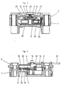
- FIG. 1 shows a housing base 1, in which three screwless conductor connecting terminals 24 I , 24 II , 24 III are preferably inserted with a clamping spring 25. Pressure leg 35, 36 of the clamping spring 25 clamp two connecting lead wires 37 in clamping grooves 38. The connecting line wires 37 can be released again by means of spring release buttons 39.
- Fixed contact parts 30, 31, 32 are inserted in contacting manner with plug-in tabs 23 in the conductor connection terminals 24.
- the plug-in lugs 23 preferably have beads 9, which serve for better locking of the respective plug-in lugs 23 in the housing wall of the conductor connection terminals 24.
- a contact rocker 10 is pivotally mounted on a contact rocker support point P of the first fixed contact part 30, which is designed as a rigid bearing contact, the pivot axis of the contact rocker 10 being perpendicular to Base floor of the housing base 1 is directed.
- the distance a I of the contact rocker support point P to the first conductor connection terminal 24 I is smaller than the distance a II of the contact rocker support point P to the second conductor connection terminal 24 II .
- a movable contact part 22 is arranged, which optionally and depending on the rocking position of the contact rocker 10 contacts either a second fixed contact part 31 or a third fixed contact part 32.
- the rocking position of the contact rocker 10 is controlled by a control cam 26 of a control rocker 8 pivotally mounted in the housing base 1.
- the control cam 26 is axially displaceable in a recess 29 of the control rocker 8 and resiliently supported by means of a control cam contact pressure spring 28.
- On the control rocker 8 two switching cams 27 are arranged, which are alternately switched by the engagement of two switching lugs 7 of a switching rocker 5.
- the rocker switch 5 is pivotally mounted on a slide switch 4 by means of a pivot bearing pin 6.
- the slide switch 4 can be moved linearly by means of a web 20 in a longitudinal groove 15 of an upper housing part 2.
- the slide switch 4 also has an integrally formed extension 13, on the end of which one end of a swivel slide return spring 3 is mounted laterally, the extension 13 resting on a first shoulder 17 of the housing base 1 and being mounted on a sliding bearing.
- a fastening pin 14 for an actuating pull cord 21 is attached on a part of the extension 13 which extends through a longitudinal recess 16 of the upper housing part 2, a fastening pin 14 for an actuating pull cord 21 is attached.
- Switch slide 4 and rocker switch 5 form a swivel slide 4, 5 that can be moved as well as swiveled.
- the rocker switch 5 rests on a second shoulder 18 of the housing base 1 and is slidingly supported.
- the switching mechanism of the electric pull switch described above is arranged on the housing base 1 in order to achieve a flat switch design in the plane of the contact parts.
- the housing base 1 is of central symmetry, that is to say that the housing base limiting points B 1, B 2 and the connecting base limiting lines b 1 2, B 2 1 connecting them are made to coincide by a 180 ° rotation about a point symmetry center M o .
Landscapes
- Switch Cases, Indication, And Locking (AREA)
Claims (2)
- Interrupteur électrique à tirette pour encastrement dans des boîtes encastrées correspondant à la norme DIN ou à la norme CEE, comprenant une partie supérieure de boîtier (2) et un socle de boîtier (1) recevant des bornes de raccordement de conducteur (24) ainsi qu'un mécanisme de commutation agencé dans le plan des bornes de raccordement de conducteur (24) et pourvu d'une bascule de contact (10), caractérisé en ce que le socle de boîtier (1) équipé de bornes de raccordement de conducteur (24I, 24II, 24III) sans vis est réalisé d'une manière centralement symétrique, les points de délimitation du socle de boîtier (B₁ à B₂) à côté des lignes de délimitation du socle de boîtier (b₁₂, b₂₁) qui les relient étant amenés à se recouvrir par une rotation du socle de boîtier (1) autour d'un centre de symétrie (M₀) de l'angle de rotation φ=180°, et en ce que la distance (aI) entre un point d'appui de bascule de contact (P) et la première borne de raccordement de conducteur (24I) est plus petite que la distance (aII) entre le point d'appui de bascule de contact (P) et la deuxième borne de raccordement de conducteur (24II).
- Interrupteur électrique à tirette suivant la revendication 1, caractérisé en ce que trois ou quatre bornes de raccordement de conducteur (24) sans vis sont de préférence agencées sur le socle de boîtier (1) centralement symétrique.
Applications Claiming Priority (2)
| Application Number | Priority Date | Filing Date | Title |
|---|---|---|---|
| DE9002939U DE9002939U1 (de) | 1990-03-15 | 1990-03-15 | Elektrischer Zugschalter |
| DE9002939U | 1990-03-15 |
Publications (2)
| Publication Number | Publication Date |
|---|---|
| EP0446842A1 EP0446842A1 (fr) | 1991-09-18 |
| EP0446842B1 true EP0446842B1 (fr) | 1994-08-31 |
Family
ID=6851922
Family Applications (1)
| Application Number | Title | Priority Date | Filing Date |
|---|---|---|---|
| EP91103699A Expired - Lifetime EP0446842B1 (fr) | 1990-03-15 | 1991-03-11 | Interrupteur à tirette électrique |
Country Status (2)
| Country | Link |
|---|---|
| EP (1) | EP0446842B1 (fr) |
| DE (2) | DE9002939U1 (fr) |
Family Cites Families (4)
| Publication number | Priority date | Publication date | Assignee | Title |
|---|---|---|---|---|
| NL110172C (fr) * | 1958-02-27 | |||
| DE2646853A1 (de) * | 1976-10-16 | 1978-04-20 | Giersiepen Eltech Ind | Elektrischer zugschalter |
| DE3214460A1 (de) * | 1982-04-20 | 1983-10-27 | Brown, Boveri & Cie Ag, 6800 Mannheim | Elektromagnetisches schaltgeraet mit schraubenlosen klemmanschlusskoerpern |
| FR2551913B1 (fr) * | 1983-09-12 | 1986-10-03 | Legrand Sa | Interrupteur a commande a tirage et tete de commande a tirage pour un tel interrupteur |
-
1990
- 1990-03-15 DE DE9002939U patent/DE9002939U1/de not_active Expired - Lifetime
-
1991
- 1991-03-11 EP EP91103699A patent/EP0446842B1/fr not_active Expired - Lifetime
- 1991-03-11 DE DE59102679T patent/DE59102679D1/de not_active Expired - Fee Related
Also Published As
| Publication number | Publication date |
|---|---|
| DE59102679D1 (de) | 1994-10-06 |
| EP0446842A1 (fr) | 1991-09-18 |
| DE9002939U1 (de) | 1990-05-17 |
Similar Documents
| Publication | Publication Date | Title |
|---|---|---|
| DE3884557T2 (de) | Ausschaltanordnung für mehrphasenleistungsschalter mit drehbarem Doppelkontakt. | |
| EP0375088B1 (fr) | Dispositif de coupure pour le trajet du courant principal d'un disjoncteur de puissance | |
| DE1665361A1 (de) | Mehrfach-Steckdose | |
| DE2505908A1 (de) | Schalter | |
| DE2833497C2 (de) | Elektrischer Lastschalter für Niederspannungsanlagen | |
| DE19856678C2 (de) | Elektrische Schaltvorrichtung | |
| EP1673795B1 (fr) | Contacteur pourvu de bornes a chassis | |
| EP0000711A1 (fr) | Contacteur avec bornes de raccordement librement accessibles et disposées dans des plans différents | |
| DE19530947C2 (de) | Klemmblock für Elektrizitätszähler | |
| DE10055035C2 (de) | Lasttrennschalter mit mindestens einem Sicherungshalter | |
| DE3620416C2 (fr) | ||
| DE19531115A1 (de) | Anschlußklemme | |
| EP1356548B1 (fr) | Dispositif de contact pour la liaison liberable d'un bloc d'assemblage mobile avec des rails conducteurs fixes | |
| DE69805922T2 (de) | Elektrisches Gerät mit Isolationsdurchdringungsklemmen | |
| EP1296431A2 (fr) | Ensemble de barres de distribution | |
| DE2548723B2 (de) | Mehrpoliger elektrischer Schalter schmaler Bauweise | |
| EP0446842A1 (fr) | Interrupteur à tirette électrique | |
| EP0310885B1 (fr) | Contacteur électrique | |
| DE29917825U1 (de) | Verbindungselement mit Querverbindung | |
| DE8504297U1 (de) | Drehschaltereinheit für ein elektrisches Handgerät | |
| DE19943734B4 (de) | Elektrischer Installationssteckverbinder mit einem Phasenwähler | |
| WO2009030719A1 (fr) | Commutateur comprenant au moins deux niveaux de commutation | |
| DE2437509C2 (de) | Sicherungstrennschalter | |
| DE2622054B2 (de) | Elektromagnetisches Schaltgerät | |
| DE10115708B4 (de) | Elektrisches Schaltgerät |
Legal Events
| Date | Code | Title | Description |
|---|---|---|---|
| PUAI | Public reference made under article 153(3) epc to a published international application that has entered the european phase |
Free format text: ORIGINAL CODE: 0009012 |
|
| AK | Designated contracting states |
Kind code of ref document: A1 Designated state(s): BE DE NL |
|
| 17P | Request for examination filed |
Effective date: 19911008 |
|
| 17Q | First examination report despatched |
Effective date: 19940214 |
|
| GRAA | (expected) grant |
Free format text: ORIGINAL CODE: 0009210 |
|
| AK | Designated contracting states |
Kind code of ref document: B1 Designated state(s): BE DE NL |
|
| PG25 | Lapsed in a contracting state [announced via postgrant information from national office to epo] |
Ref country code: NL Effective date: 19940831 |
|
| REF | Corresponds to: |
Ref document number: 59102679 Country of ref document: DE Date of ref document: 19941006 |
|
| NLV1 | Nl: lapsed or annulled due to failure to fulfill the requirements of art. 29p and 29m of the patents act | ||
| PG25 | Lapsed in a contracting state [announced via postgrant information from national office to epo] |
Ref country code: BE Effective date: 19950331 |
|
| PLBE | No opposition filed within time limit |
Free format text: ORIGINAL CODE: 0009261 |
|
| STAA | Information on the status of an ep patent application or granted ep patent |
Free format text: STATUS: NO OPPOSITION FILED WITHIN TIME LIMIT |
|
| 26N | No opposition filed | ||
| BERE | Be: lapsed |
Owner name: ASEA BROWN BOVERI A.G. Effective date: 19950331 |
|
| PG25 | Lapsed in a contracting state [announced via postgrant information from national office to epo] |
Ref country code: DE Effective date: 19951201 |