EP0446915B1 - Kamera für selbstausfädelnde Filmpatronen - Google Patents
Kamera für selbstausfädelnde Filmpatronen Download PDFInfo
- Publication number
- EP0446915B1 EP0446915B1 EP91103931A EP91103931A EP0446915B1 EP 0446915 B1 EP0446915 B1 EP 0446915B1 EP 91103931 A EP91103931 A EP 91103931A EP 91103931 A EP91103931 A EP 91103931A EP 0446915 B1 EP0446915 B1 EP 0446915B1
- Authority
- EP
- European Patent Office
- Prior art keywords
- film
- feeding
- blank
- rewinding
- further characterized
- Prior art date
- Legal status (The legal status is an assumption and is not a legal conclusion. Google has not performed a legal analysis and makes no representation as to the accuracy of the status listed.)
- Expired - Lifetime
Links
- 238000001514 detection method Methods 0.000 claims description 18
- 238000012840 feeding operation Methods 0.000 claims 8
- 238000004904 shortening Methods 0.000 claims 2
- 238000004804 winding Methods 0.000 description 95
- 230000006870 function Effects 0.000 description 26
- 238000010276 construction Methods 0.000 description 20
- 230000007246 mechanism Effects 0.000 description 11
- 238000010586 diagram Methods 0.000 description 8
- 238000005375 photometry Methods 0.000 description 7
- 238000000034 method Methods 0.000 description 6
- 239000007787 solid Substances 0.000 description 6
- 230000009471 action Effects 0.000 description 5
- 239000000428 dust Substances 0.000 description 5
- 230000001133 acceleration Effects 0.000 description 4
- 238000012790 confirmation Methods 0.000 description 2
- 238000005259 measurement Methods 0.000 description 2
- 230000002093 peripheral effect Effects 0.000 description 2
- 230000001360 synchronised effect Effects 0.000 description 2
- 230000007704 transition Effects 0.000 description 2
- 230000005856 abnormality Effects 0.000 description 1
- 230000004913 activation Effects 0.000 description 1
- 210000000078 claw Anatomy 0.000 description 1
- 230000001419 dependent effect Effects 0.000 description 1
- 238000003384 imaging method Methods 0.000 description 1
- 239000000463 material Substances 0.000 description 1
- 230000013011 mating Effects 0.000 description 1
- 235000012054 meals Nutrition 0.000 description 1
- 238000012986 modification Methods 0.000 description 1
- 230000004048 modification Effects 0.000 description 1
- 230000003287 optical effect Effects 0.000 description 1
- 239000000843 powder Substances 0.000 description 1
- 238000012545 processing Methods 0.000 description 1
- 230000035945 sensitivity Effects 0.000 description 1
- 239000002699 waste material Substances 0.000 description 1
Images









Classifications
-
- G—PHYSICS
- G03—PHOTOGRAPHY; CINEMATOGRAPHY; ANALOGOUS TECHNIQUES USING WAVES OTHER THAN OPTICAL WAVES; ELECTROGRAPHY; HOLOGRAPHY
- G03B—APPARATUS OR ARRANGEMENTS FOR TAKING PHOTOGRAPHS OR FOR PROJECTING OR VIEWING THEM; APPARATUS OR ARRANGEMENTS EMPLOYING ANALOGOUS TECHNIQUES USING WAVES OTHER THAN OPTICAL WAVES; ACCESSORIES THEREFOR
- G03B17/00—Details of cameras or camera bodies; Accessories therefor
- G03B17/42—Interlocking between shutter operation and advance of film or change of plate or cut-film
- G03B17/425—Interlocking between shutter operation and advance of film or change of plate or cut-film motor drive cameras
-
- G—PHYSICS
- G03—PHOTOGRAPHY; CINEMATOGRAPHY; ANALOGOUS TECHNIQUES USING WAVES OTHER THAN OPTICAL WAVES; ELECTROGRAPHY; HOLOGRAPHY
- G03B—APPARATUS OR ARRANGEMENTS FOR TAKING PHOTOGRAPHS OR FOR PROJECTING OR VIEWING THEM; APPARATUS OR ARRANGEMENTS EMPLOYING ANALOGOUS TECHNIQUES USING WAVES OTHER THAN OPTICAL WAVES; ACCESSORIES THEREFOR
- G03B17/00—Details of cameras or camera bodies; Accessories therefor
- G03B17/28—Locating light-sensitive material within camera
- G03B17/30—Locating spools or other rotatable holders of coiled film
-
- G—PHYSICS
- G03—PHOTOGRAPHY; CINEMATOGRAPHY; ANALOGOUS TECHNIQUES USING WAVES OTHER THAN OPTICAL WAVES; ELECTROGRAPHY; HOLOGRAPHY
- G03B—APPARATUS OR ARRANGEMENTS FOR TAKING PHOTOGRAPHS OR FOR PROJECTING OR VIEWING THEM; APPARATUS OR ARRANGEMENTS EMPLOYING ANALOGOUS TECHNIQUES USING WAVES OTHER THAN OPTICAL WAVES; ACCESSORIES THEREFOR
- G03B2217/00—Details of cameras or camera bodies; Accessories therefor
- G03B2217/26—Holders for containing light-sensitive material and adapted to be inserted within the camera
- G03B2217/266—Thrust-type cartridges
Definitions
- This invention relates to a camera utilizing a push-out type film cartridge which is so constructed that the film being wholly stored in a film cartridge is pushed out from the outlet of said film cartridge by means of transition of driving force to a feed spool equipped inside said film cartridge.
- Document EP-A-0 430 669 which is a postpublished prior art document claiming an earlier priority, discloses a film feeding apparatus in a camera.
- This apparatus comprises film feeding means for feeding film from a film cartridge and take-up spool means for taking up the film fed by said feeding means.
- the movement speed of the film is determined by the feeding means before the film extending from the film cartridge is taken up by the take-up spool means and the movement speed of the film is determined by the take-up spool means after the film has been taken up by the take-up spool means.
- the movement speed of the film driven by the feeding means differs from the movement speed of the film driven by the take-up spool means.
- judgment means are provided for judging on the basis of a variation in the movement speed of the film whether the film has been taken-up by the take-up spool means.
- detecting means for detecting that the film is not wound on the spool and outputting a detection signal
- rewinding means responsive to said detection signal to rewind the film into the cartridge
- driving means for driving the feeding means after the completion of the rewinding of the film by the rewinding means to thereby feed the film again from the film cartridge to the spool side.
- a film cartridge and a camera employing the film cartridge is known.
- the perforations formed on a leading portion of a film not used are in engagement with the engaging claws of a sprocket.
- a microcomputer counts a pulse number output by a sprocket-rotational amount detecting circuit corresponding to the rotational amount of the sprocket.
- a decision is made that the counting of the timer is terminated, i.e. a decision is made that the predetermined amount of the film is not fed out of the film case, as a result of occurrence of an abnormality.
- the number of photographable frames is stored correspondingly with the number of perforations formed on the film.
- Document US 4 716 428 discloses an automatic film loading device for a camera arranged to automatically feed the camera with a film to an extent of obtaining a first photographable frame portion of the film after film loading.
- This device comprises a first switch means to open and close for every frame portion of the film and a second switch means arranged to open and close a plurality of times during frame feeding.
- a control means counts the number of time for which the position of the second switch means changes before the position of the first switch means changes after film loading and controls the number of blank frame portions to be fed up to the first of the photographable frame portions according to a counted value thus obtained.
- a film winding detection means includes a rotation detecting wheel which is arranged to rotate following the movement of the film when the film is wound up.
- document US 4 878 075 discloses a camera having film feeding means adapted for using a self-thrusting type of film cartridge.
- the film feeding means is arranged for driving a feed spool of said self-thrusting type film cartridge to feed the film therein contained out of the cartridge.
- a control means causes said film feeding means to rewind the film in the case of a stall of the driving motor, i.e. at the end of the film, or in case of detecting a DEP flag, i.e. when the respective frame is already exposed.
- the film feeding means stops after positioning a first available imaging area of the filmstrip F to an exposure position.
- This invention taking the above mentioned inconvenience into consideration, is intended to provide a camera which utilizes a push-out type film cartridge that is so constructed that the revolution of a feed spool equipped therein feeds out the film.
- the camera according to the invention has the features outlined in claim 1. Film feeding means for such a camera are set out in claim 21. Modifications thereof are set forth in the dependent claims.
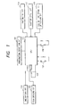
- Figure 1 is a camera circuit diagram of one of the embodiments of the present invention.
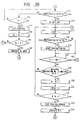
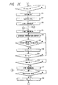
- Figure 2 is a flow chart showing the functions of the above circuit of Figure 1.
- Figure 3 is a side view showing the film cartridge relating to the present invention.
- Figure 4 is a horizontal cross-sectional view of the above film cartridge.
- Figure 5 is a cross-sectional view taken along line A - A of Figure 4.
- Figure 6 is a back view of the camera of Figure 1.
- FIGS 7 and 8 are side views of the film feeding mechanism of the camera of Figure 1.
- Figure 9 is a camera circuit diagram of one of the other embodiments of the present invention.
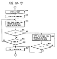
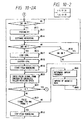
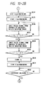
- FIGS 10-1 and 10-2 are flow charts showing the functions of the camera.
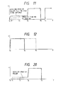
- Figure 11 shows the speeds of the film end and roller member at the time of automatic loading.
- Figure 12 shows the speeds of the film end and roller member at the time of film rewinding.
- FIGS 13 and 14 show flow charts where Figure 10-1 is partly modified.
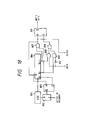
- Figure 15 is a circuit diagram showing an example of a specific construction of the head control circuit as indicated in Figure 9.
- FIGs 16 and 17 show the output wave forms of each portion of Figure 15.
- Figure 18 shows a circuit diagram of a construction of the hardware for the processing of the write-in frequency determination to be done in the microcomputer as indicated in Figure 9.
- Figure 19 shows an example of the other functions of the circuit of Figure 9.
- Figure 20 shows the speeds of the film end and roller member at the time of automatic loading.
- Figure 21 shows a side view of the film feeding mechanism utilized in this embodiment example.
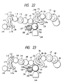
- Figure 22 is a plan view showing gear arrangements at the time of film winding of said embodiment example.
- Figure 23 is a plan view showing gear arrangements at the time of film rewinding of said embodiment example.
- Figure 24 is a vertical cross-sectional view of the one-way clutch mechanism as indicated in Figure 21.
- Figure 25 is a plan view of the critical construction of the one-way clutch mechanism as indicated in Figure 21.
- Figure 26 is a side cross-sectional view showing the construction of the critical components of the camera of this embodiment example.
- Figures 27 and 28 are plan views showing different examples other than those examples of the roller member driving gear arrangements shown in Figures 21 through 23.
- Figure 29 is a vertical cross-sectional view showing the other construction of the pulse signal generating portion.
- Figure 30 is a plan view showing a location between the magnetic head and roller member as indicated in Figure 21.
- Figure 31 is a vertical cross-sectional view showing a different location between the magnetic head and roller member.
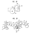
- Figure 32 is a plan view showing a different location between the magnetic head and roller member.
- Figure 33 is plan view showing a construction example of film feeding gear arrangements based on the location of Figure 32.
- Figure 6 shows a back view of an embodiment of the camera of the present invention where the back plate is omitted for explanatory conveniences.
- 1 is a camera main body
- 2 is a ditch to mate with the back plate
- 3 is an opening portion where an aperture is located.
- 4 are inside rails for film guiding and 5 are outside rails for film guiding, the inside rails 4 being used to determine the film position in the front-back direction (light axis direction) and the outside rails 5 being used to determine the film position in the up-down direction.
- 6 is a cartridge chamber, which accommodates a push-out type film cartridge to be mentioned hereinafter.
- 7 is a fork as a spool engagement member which engages with a feed spool located inside the film cartridge and is driven by a film feeding mechanism of the camera to be mentioned hereinafter.
- 8 is a winding spool located in the spool chamber 9 and is so constructed that the film tip is automatically wound by rollers 10 and 11 utilizing such a a known means as that indicated in Japanese Laid-Open Patent document JP 60-45231 A, corresponding to US 4 579 435 A. .
- Figures 3 through 5 show an embodiment of a push-out type film cartridge to be used in the embodiment of the camera of the present invention, Figure 3 being a side view thereof, Figure 4 being a horizontal cross-sectional view thereof and Figure 5 a cross-sectional view taken along line A - A of Figure 4.
- 21 is a chassis of the cartridge, in which the feed spool 22 is axially supported for revolution. Also, said feed spool 22 has an engagement portions 22a at both ends which engage with said fork 7. 23 are rollers, which are axially supported in the chassis 21.
- the embodiment hereof is so constructed that three rollers 23 and the internally protruded portion 21a of the chassis 21 get in touch with the outside most of the film wound on the feed spool 22. Consequently, when the feed spool 22 is turned in the film pushing-out direction (counterclockwise in Figure 4), the film 24 will be unwound and pushed out from the opening 25.
- Figures 7 and 8 show a film feeding mechanism of the embodiment of the camera hereof, Figure 7 showing the state from the film pushing-out to the film winding and Figure 8 showing the state of the film rewinding.
- 31 is a film driving motor where the pinion 32 is stationed to the output axis 31a.
- 8 is the winding spool as described in Figure 5, and 10 and 11 are rollers.
- the winding gear 34 is installed above the winding spool 8 through the one-way clutch 33.
- the one-way clutch 33 is, for example, a known free revolution clutch as indicated in Japanese Laid-Open Patent document No. JP 55 -17175 A (corresponding to US A 272 173 A) assigned to the applicant hereof, and relays driving forces to the winding spool 8 when the winding gear 34 in Figure 7 turns counterclockwise, but reversely does not relay driving force when the gear 34 turns clockwise.
- 35 is a two-stack gear connecting said pinion 32 with the winding gear 34.
- the pinion 32, two-stack gear 35 and the winding gear 34 comprise the gear train for film winding.
- a sun gear axially supporting a planetary lever 37 on a axis 36a for revolution, and on the top of which a gear 38 is stationed.
- 39 is a two-stack gear connecting the pinion 32 with the gear 38.
- a planetary gear 40 is axially supported for revolution.
- 7 is the fork described in Figure 6, on the top of which a rewinding gear 41 is stationed. Further on the rewinding gear 41, a push-out gear 43 is located through a one-way clutch 42.
- the one-way clutch 42 is of the same construction as of said one-way clutch 33, and relays driving force to the fork 7 when the push-out gear 43 is turned counterclockwise in Figure 7, but reversely does not relay driving force when the push-out gear 43 is turned clockwise.
- Said planetary gear 40 is to engage with said push-out gear 43 as shown in Figure 7 when said sun gear 36 being in the state of Figure 8 is turned counterclockwise.
- the pinion 32, the two-stack gear 39, the gear 38, the sun gear 36, the planetary gear 40 and the push-out gear 43 comprise the gear train for film pushing-out.
- the reduced speed ratio of the gear train thereof is to be set greater than that of said gear train for film winding.
- the larger gear 45a of the two-stack gear 45 connected with the rewinding gear 41 through the gear 44 is to engage with the planetary gear 40 as shown in Figure 8 when the sun gear 46 is turned clockwise in Figure 7.
- the pinion 32, the two stack gear 49, the gear 48, the sun gear 46, the planetary gear 40, the two-stack gear 45, the gear 44 and the rewinding gear 41 comprise the gear train for film rewinding.
- the reduced speed radio of the gear arrangements thereof is to be set greater than that of said gear arrangements for film winding.
- the cartridge chassis 21 indicated in Figure 3 is to be loaded into the cartridge chamber 6, but at this time the film 24 is not being pushed out from the opening 25 of the cartridge chassis 21.
- the back plate not indicated in the figure, is closed, the back plate switch (indicated in Figure 1) to be mentioned hereinafter will be turned on, the signal from which will excite the driving motor 31 to rotate first clockwise in Figure 7.
- the sun gear 36 will also turn clockwise, while the planetary gear 40 will revolve around the sun gear 36 clockwise, reaching the state of Figure 8.
- each gear of 32, 39, 38, 36, 40, 45, 44 and 41 are connected with each other while the rewinding gear 41 turns clockwise and the fork 7 in the same solid construction as of said gear 41 also turns clockwise.
- the feed spool 22 engaged with the fork 7 turns clockwise in Figure 3 to rewind the film 24.
- the rewinding thereof can eliminate sticking of the film tip, due to dust or sticky matter, inside the film cartridge without causing the film to be bent.
- the film driving motor 31 is to be turned counterclockwise.
- the sun gear 36 turns counterclockwise, so that the planetary gear 40 revolves around the sun gear 36 counterclockwise, reaching the state of Figure 7 where a planetary 40 is connected with the push-out gear 43.
- the push-out gear 43 being turned counterclockwise, driving force is relayed to the one-way clutch 42, causing the fork 7 to turn counterclockwise. Since the fork 7 is engaged with the engagement portions 22a of the feed spool 22 inside the cartridge chassis 21, the feed spool 22 turns counterclockwise in Figure 4, causing the film 24 to be pushed-out from the opening 25.
- the film 24 is pushed out without being bent, since the tip of the film does not get stuck with dust or sticky matters inside the cartridge.
- the tip of the film 24 reaches the winding spool.
- the film driving motor 31 starts turning counterclockwise
- the winding spool 8 turns counterclockwise as driven by the gear train for film winding consisting of each gear of 32, 35, and 34.
- the one-way clutch 33 is relaying driving force, since the winding gear 34 is turning counterclockwise.
- the tip of the film 24 is wound around the winding spool 8, starting the winding function.
- the revolution of the winding gear 34 becomes faster than that of the push-out gear 43 in that the reduced speed ratio of the gear arrangements for film pushing-out is larger than that of the gear arrangements for film rewinding.
- the fork 7 is driven by the winding gear 34 through the winding spool 8, the film 24 and the feed spool 22, so that said fork 7 turns faster than the push-out gear 43, causing the one-way clutch 42 to cut off the relaying of driving force.
- the push-out gear 43 looks turning reversely in a relative view, causing the one-way clutch 42 to cut off the relaying of driving force. Consequently, as soon as the tip of the film 24 starts wound around the winding spool 8, the winding spool 8 alone starts the winding function for the film 24.
- winding gear also turns clockwise, but since the reduced speed ratio of the gear arrangements for film rewinding is larger than that of those for film winding as mentioned, the revolution of the winding gear 34 becomes faster than that of the winding spool 8 turning clockwise driven through the fork 7, the feed spool 22 and the film 24, causing the one-way clutch 33 to cut off the relaying of driving force.
- the film can be rewound without causing any interruption to the gear train for film winding.
- film cartridges compatible with the film feeding system aforementioned are not limited to the one used in said embodiment, and can be of any other construction where the film can be pushed out from the film cartridge as a result of the revolution of the feed spool.
- Figure 1 is an example of an electric circuit block diagram that can control the functions thereof.
- 101 is a perforation detection circuit consisting of photo reflector capable of detecting the perforation of said film 24;
- 102 is a film driving circuit which drives motor 31 that does the winding and rewinding as well as the pushing-out of said film 24;
- 103 is a CPU, which is a micro-computer that controls the whole of the camera;
- 104 is a photometry circuit directing an appropriate light exposure to the film 24;
- 105 is a shutter control circuit controlling the opening/closing of the shutter;
- 106 is a back plate switch for turning on/off corresponding to the opening/closing of the back plate;
- 107 is a release switch for turning on/off corresponding to the manipulation by the photographer of the shutter release button;
- 108 is a cartridge detection switch detecting whether the film cartridge is loaded or not;
- 109 is an ISO and frame numbers detection circuit detecting ISO data and a number of frames of the film 24;
- 110 is an indication circuit alarming a blank feeding failure.
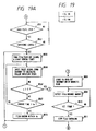
- FIG. 2 is a flow chart showing the functions of CPU 103 indicated in Figure 1. In accordance with the flow chart thereof, the functions of the circuit indicated in Figure 1 will be described hereinafter.
- Step 201 whether the back plate is open or closed is identified by checking the status of a back plate switch 106. If the back plate is closed, Step 201 proceeds to Step 202, and if it is open, Step 201 is repeated.
- Step 202 whether the film cartridge is loaded or not is identified by checking the status of a cartridge detection switch 108. If the cartridge is loaded, Step 202 proceeds to Step 203, and if it is not loaded, steps 201 and 202 are repeated.
- Step 203 the number of the frames in the film 24 is detected by the ISO and frame numbers detection circuit 109.
- Step 204 whether the frames number information exists or not is identified. If such information exists, Step 204 proceeds to Step 205, and if it does not exist, Step 204 proceeds to Step 206.
- timer times T1 and T2 are set depending upon the number of the frames. This is because the amount of the spool to be blank fed differs when there are variations in the number of the frames existing in from one film to another to be loaded into same film cartridge. When the number of the frames left unphotographed is high, the timer times T1 and T2 should be set shorter, and when the number of the frames left unphotographed is low, the timer times T1 and T2 should be set longer.
- the timer times T1 and T2 are set at the specified values corresponding to the longest time possible, since the information on the number of the frames is not available.
- Step 207 the value of the film counter N is reset to "0".
- Step 208 the rewinding of the film 24 in the cartridge chassis 21 is done as mentioned by the film driving circuit 102.
- Step 209 the timer time T1 set at either Step 205 or 206 is counted. Step 209 proceeds to Step 210 upon the counting.
- a film driving motor 31 is made to stop, completing the rewinding function of said film 24.
- Step 211 as mentioned the film driving motor 31 is made to rotate in the reverse direction as aforesaid, so that the film 24 is pushed-out from the cartridge chassis 21.
- Step 212 the timer time T2 set at either Step 5 or 6 starts to be counted.
- Step 213 perforations are detected by a perforation detection circuit 101.
- the detection method at this step is such that although the tip of the film does not have a perforation, said perforation circuit can substitutionally detect said film 24 being fed, by said push-out function, into where the film 24 did not exist. If perforations are not detected hereof, Step 213 proceeds to Step 214.
- Step 214 whether the timer time T2 has elapsed or not is identified. If it has not elapsed, Steps 213 and 214 are repeated, and if it has elapsed, the blank feeding is deemed not to have been done properly, and therefore Step 214 proceeds to Step 215.
- Step 215 the film driving motor 31 is made to stop, and Step 215 proceeds to Step 240.
- Step 240 one is added to the value of the blank feeding counter AL indicating the number of the blank feeding times.
- Step 241 whether the number of the blank feeding times has exceeded four times or not is judged, and if it has not exceeded four times, Step 241 returns to Step 201, where blank feeding is repeated after rewinding is done.
- Step 241 proceeds to Step 242 without further repeating the blank feeding function based on an assumption that the blank feeding function does not go successful even if blank feeding is repeated any further.
- the judgment of the blank feeding times is set at four times, but the number can be set at any figure depending on requirements.
- Step 242 the indication circuit 110 is made to indicate Al (automatic loading) miss which means a blank feeding failure, and then Step 242 proceeds to Step 243.
- Step 243 waits until the back plate becomes open (identified by the status of back plate switch 106) and the film 24 is removed, and upon the opening of the back plate, proceeds to Step 244 where the blank feeding counter AL is reset to "0", and then returns to Step 201.
- Step 213 proceeds to Step 239.
- Step 239 AL miss indication indicated by indication circuit 110 is turned off (and if AL Miss is not indicated in the figure, then directly proceeds to Step 217).
- Step 217 the timer T3 is made to start.
- Step 218 perforations are detected by the perforation detection circuit 101. If perforations are detected, Step 218 proceeds to Step 219, and if perforations are not detected, Step 218 proceeds to Step 220.
- Step 219 the number of the perforations is counted.
- said timer T3 judges whether it has elapsed one second or more not (the number of seconds is longer time than that expected to be required in the film winding can be set at any figure depending on requirements), and if it has elapsed one second or more, namely meaning that there were no perforations detected even after winding for one second or more, it is judged that the photographing of the last frame of the film 24 has been complete so that the pushing-out of the film cannot be done any further, causing Step 220 to proceed to Step 221.
- Step 221 the film driving motor 31 is driven so that the film 24 starts to be rewound as aforesaid.
- the perforation counter is reduced each time a perforation is detected.
- Step 223 whether the value of the perforation counter is in increments of 8 or not (based on an assumption that the rewinding for one frame completes when the counter counts 8 perforations) is judged, and if it is in increments of 8, Step 223 proceeds to Step 224, and if it is not in increments of 8, Step 223 returns to Step 222.
- Step 224 one number is reduced from the value of the film counter N.
- Step 225 whether the value of the film counter is "0" or not is judged, and if it is not “0", Step 225 returns to Step 222, and if it is "0", Step 225 proceeds to Step 226.
- Step 226 the function in the winding direction is continued for the set time duration.
- Step 227 the driving for the driving motor 31 is made to stop, and Step 227 proceeds to said Step 243.
- Step 220 proceeds to Step 229.
- Step 229 whether the value of the perforation counter is in increments of 8 or not (based on an assumption that the winding for one frame completes when the counter counts 8 perforations) is checked. If it is not in increments of 8, Step 229 returns to Step 217, and if it is in increments of 8, Step 229 proceeds to Step 230.
- Step 230 one number is added to the value of the film counter N.
- Step 232 whether "N ⁇ 4" or not is judged, and if N ⁇ 4, Step 232 returns to Step 217, and if N ⁇ 4, Step 232 proceeds to Step 233. This is based on an assumption that three frames from the film tip is blank fed and that the fourth frame is used as the first frame to be photographed.
- Step 233 the film driving motor 31 is made to stop, causing the film winding to be stopped.
- Step 234 the value of "film counter value N-3" is indicated on the indication circuit 110.
- Step 235 whether the release switch 107 is turned on or not is judged, and if Step 235 detects the switch 107 is turned on, it proceeds to Step 236.
- the photometry circuit 104 is activated to obtain photometry information.
- Step 237 the shutter control circuit 105 is activated to do the opening/closing of the shutter.
- Step 238 one-frame winding of the film 24 is made to start and Step 238 returns to Step 217, repeating the photographing sequence.
- rewinding may be done for a specified time duration.
- the indication circuit alarming a blank feeding failure can be of any type such as ones including a buzzer.
- Figures 21 through 26 shows mechanical constructions related to each embodiment hereinafter, Figure 21 being a side view of a film feeding mechanism, Figure 22 being a plane view of gear arrangements at the time of film winding, Figure 23 being a plane view of gear arrangements at the time of film rewinding, Figure 24 being a cross-sectional view of a one-way clutch, Figure 25 being a side cross-sectional view thereof, and Figure 26 being a side cross-sectional view of critical components of the camera.
- 301 is a film driving motor which turns forward (in the arrow B direction in Figure 22) for film winding and turns backward (in the arrow C direction in Figure 23) for film rewinding.
- 302 is a pinion gear to be stationed on the rotational axis of said motor 301.
- 303 is a first planetary gear engaged with said pinion gear 302.
- 304 is a first planetary gear engaged with said first sun gear 303.
- 305 is a first connecting lever connecting the first sun gear 303 with a first planetary gear 304 where the first connecting lever 305 supports said first planetary gear 304 rotatable in creating a frictional force against the first planetary gear 304, so that turning the first sun gear 303 causes the first planetary gear 304 to revolve around the sun gear 303 with the gear 303 being the center of the revolution.
- Said first sun gear 303, first planetary gear 304 and first connecting lever 305 comprise a known planetary gear mechanism.
- 306 is a spool gear that engages with a first planetary gear 304 only when said film driving motor 303 turns forward.
- 307 is a film winding spool stationed to said spool gear 306 and moves with the spool gear 306 in a solid manner.
- 308 is a first idler gear that always engages with said first sun gear 303.
- 309 consists of the larger gear part 309a and smaller gear part 309b, 309a being a first tack gear engaged with said first idler gear 308.
- 310 is the second idler gear engaged with the smaller gear part 309b of said first two-stack gear 309.
- 311 is the third idler gear engaged with said second idler gear 310.
- 312 is the second sun gear engaged with said third idler gear 311.
- 313 is a second planetary gear engaged with said second sun gear 312.
- 314 is a third planetary gear and like said second planetary gear 313, is engaged with the second sun gear.
- 315 is a second connecting lever connecting said second sun gear 312, second planetary gear 313 and third planetary gear 314 together respectively with the arm parts 315a and 315b where each planetary gear is supported rotatable by means of creating a frictional force, so that turning the second sun gear 312 causes a second planetary gear 313 and the third planetary gear 314 to revolve around said second sun gear 312 with the sun gear 312 being the center of the revolution.
- Said second sun gear 312, second and third planetary gears 313 and 314, and a second connecting lever 315 comprise a known planetary gear mechanism.
- 317 is a fourth idler gear, and engages with the second planetary gear 313, but not with the third planetary gear 314, upon the counterclockwise revolution of the second connecting lever 315 with the second sun gear 312 being the center of the revolution when the film driving motor 301 turns forward, and engages with the third planetary gear 314, but not with the second planetary gear 313, upon the clockwise revolution of the second connecting lever 314 when the film driving motor 301 turns backward.
- 317 consists of the larger gear part 317a and smaller gear part 317b, the larger gear part 317a being the second two-stack gear engaged with the fourth idler 316.
- 318 consists of the larger gear part 318a and smaller gear part 318b, the larger gear 318a being the third two-stack gear engaged with the smaller gear part 317b of said second two-stack gear 317.
- 319 is a fork gear engaged with the smaller gear part 318b of said third two-stack gear 318.
- 320 is a fork turning with said fork 319 in a solid piece manner, and turns the feed spool inside the film cartridge 333 (refer to Figure 26), pushing-out/winding the film 334 from the inside of the above cartridge 333.
- 322 and 329 are one-way clutches, 321 being a gear engaged with the second sun gear 312, 322 being a ratchet gear which has the teeth part 322a all around the inside peripheral and the gear 322b outside as shown in Figure 25, and 329 being a ratchet pawl member having the resilient pawl parts 329b engaging with the teeth part 322a of the ratchet gear 322.
- said ratchet pawl member 329 has the pin 329a mating with the hole 321c of the gear 321 so that the ratchet pawl member 329 always turns with the gear 321 in a solid piece manner.
- 330 is an base plate (not indicated in the figure) where the gear 321, the ratchet pawl member 329, and each hole of 321b, 329c and 322c of the ratchet gear 322 are respectively mated for revolution as shown in Figure 24.
- 323 is a roller member stationed to the ratchet gear 322 where the out side peripheral part 323a is provided with rubber or roulette so that slipping can be prevented.
- 324 is a pulse gear engaged with the gear part 322b of the ratchet gear 322.
- 325 is a pulse plate consisting of the conductive part 325a and a non-conductive part 325b, and is stationed onto said pulse gear 324.
- 326 and 327 are contractors to detect the pulses equivalent to the amount of the revolution of the roller member 323 by means of contacting the conductive part 325a and non-conductive part 325b of the pulse plate 325.
- 328 is a stopper (refer to Figure 23) stationed to the base plate (not indicated in the figure) and controls the counter-clock revolution position of said first connecting lever 305 by contacting an end part 305a of the first connecting lever 305.
- 331 is a camera main body (refer to Figure 26)
- 332 is a pressing plate
- 335 is a cartridge chamber
- 336 is a spool chamber.
- 348 is a magnetic head equipped on said pressing plate 332.
- Said roller member 323 is located as shown in Figure 26 where a magnetic head 348 is preset to pressurize from the beginning so that the magnetic memory-part (not indicated in the figure) can stably get in touch with said magnetic head 348, or where said magnetic head 348 is installed a certain clearance away from the roller member 323 so that a thickness of a film 334 provides a required pressure to the magnetic head 348 while the film 334 passes through the clearance between the magnetic head 348 and roller member 323.
- said roller member 323 comprises one film feeding system, and rotates as the film 334 moves. In connection thereof, the pulse plate 325 rotates through the gear 322 so that a pulse signal takes place at contractors 326 and 327.
- the driving force thereof is relayed through the idler gear 308, which is another gear engaged with said first sun gear 303, and further through a first two-stack gear 309, a second idler gear 310 and a third idler gear 311 to a second sun gear 312.
- the sun gear rotates counterclockwise, due to the action of the second connecting lever 315, a second planetary gear 313 and a third planetary gear 314 revolves with said second sun gear being the center of the revolution. Shortly the second planetary gear 313 becomes to engage with a fourth idler gear 316.
- the driving force in the arrow B direction of said film driving motor 301 is relayed to the fourth idler gear 316 as the counterclockwise driving force, and is further relayed to the fork 320 through the second two-stack gear 317 and the third two-stack gear 318, causing the fork 320 to rotate clockwise.
- the clockwise driving force (in the arrow A direction) is relayed to the gear 321 engaged with said second sun gear 312.
- the one way clutch rotates in a solid piece manner (details of which will be mentioned hereinafter).
- the roller member 323 also rorates clockwise.
- the pulse gear 324 engaged thereof also rotates where a set of the pulse plate 325 and the contractors 326 and 327 gives off a pulse signal equivalent to the amount of the revolution of said roller member 323.
- the pulse signal thereof is detected by the encoder circuit indicated in Figure 1 (to be mentioned hereinafter) where the revolution speed and the amount of the revolution of the roller member 323 (the feeding speed and feeding amount of the film 334) are calculated.
- the reduced speed ratios of the gear arrangements thereof are set as follows.
- the film tip becomes in contact with both the roller member 323 and the magnetic head 348 in that the roller member 323 always pushes said film 334 onto the magnetic head 348.
- the film tip can be smoothly fed from the right to the left in Figure 22 by means of the frictional force between the film 334 and the roller member 323.
- the rotation speed is set at "V2 > V3"
- the driving force (speed) thereof is relayed through the film 324 to, in turn, the fork gear 319, the third two-stack gear 318, a second two-stack gear 317 and the fourth idler gear 316 where the speed to the counterclockwise revolution of a fourth idler gear 316 becomes higher than that of the clockwise revolution of the second planetary gear 313.
- the fourth idler gear 316 flips the second planetary gear 313 so that momentarily the second planetary gear 313 disengages from the fourth idler gear 316, absorbing the difference in the speeds.
- the roller member 323 starts to rotate due to the frictional force between the roller member 323 and the film 324 as a result of the relation "V1 > V2 > V3". Said roller member 323 rotates faster than the gear 321, but the rotational force of the roller member 323 is not relayed to the gear 321 due to the action of the aforementioned one-way clutch.
- the feeding amount and feeding speed of the film 334 can be calculated by the encoder circuit indicated in Figure 9 based on pulse signal, generated from the set of the pulse plate 325 and contractors 326 and 327. Furthermore, due to the relation "V1 > V2", the feeding speed will greatly vary at the moment the film 334 is wound onto the film winding spool 307, but by looking at this speed variation, whether the automatic loading is completed or not can be judged.
- the second sun gear 312 rotates clockwise where a second planetary gear 313 and a third planetary gear 314 revolve clockwise with said second sun gear 312 being the center of the revolution due to the action of the second connecting lever 315.
- the fourth idler gear 316 disengages from the second planetary gear 313, and instead the fourth idler gear 316 engages with the third planetary gear 314.
- the fork gear 319 rotates counterclockwise while the fork 320 causes the feed spool inside the film cartridge 333 (not indicated in the figure) to rotate reversely so that the film 334 starts to be wound into said cartridge 333.
- the roller member 323 is made to rotate counterclockwise by the film 334, the second sun gear 312 causes the gear 321 to rotate faster counterclockwise.
- the relative speed of the gear 321 against the ratchet gear 322 is in the counter-clock direction (as opposed to the arrow A direction) so that the driving force is not relayed from the ratchet gear 322 to the gear 321 due to the one-way clutch mechanism.
- the detection results of the feeding amount and feeding speed of the film 334 are, for example, synchronized with the magnetic head 348 at the time of magnetic recording and are used to save a required magnetic memory into a specified position of the magnetic memory part. Also, said results can be used for the feeding control for one frame of the film 334 and utilized for the writing-in of information by such optical means as LED.
- Figures 27 and 28 show one of the other embodiments of said one-way clutch consisting of 321, 322 and 329 indicated in Figures 21 through 23, Figure 27 being a plane view of the gear arrangements for film winding and Figure 28 being a plane view of the gear arrangements for film rewinding.
- 342 is the third sun gear engaged with the second sun gear 312; and 343 is the fourth planetary gear engaged with said third sun gear 342.
- 344 is the third connecting lever connecting said third sun gear with said fourth planetary gear 343, and causes the fourth planetary gear 343 to revolve counterclockwise with said third sun gear 342 being the center of the revolution when the third sun gear 342 turns counterclockwise, and causes the fourth planetary gear 343 to revolve clockwise when the third sun gear 342 turns clockwise.
- 345 is a gear engaged with said fourth planetary gear 343, to which the roller member 323 is installed in a one-piece construction. The gear 345 thereof is also engaged with the pulse gear 324.
- 346 is a stopper controlling the counterclockwise revolution of the third connecting lever 344.
- the circumferential velocity of the film winding spool 307, the circumferential velocity of the roller member 323 and the velocity of the film 334 pushed-out by the fork 320 are set at "V1 > V2 > V3" so that the gear 345 receives through the roller member 323, a counterclockwise driving force that is faster in speed than that relayed from the third sun gear 342 when the film 334 is wound onto the spool 307 at the time of film rewinding, but then the gear 345 flips the fourth planetary gear 343 toward the arrow D direction, absorbing the difference in the speeds.
- the pulse plate 325 and the contractors 326 and 327 are used to detect the film feeding amount, but in Figure 29, the pulse gear 324 is used so that the film feeding amount can be optically detected by such means as a photo-interrupter.
- 348 is a photo-interrupter
- 347 is a slit disc plate made of light-shielding materials stationed to the pulse gear 324 having the slit 347a.
- the slit 347a is detected by the photo-interrupter 347, generating pulse signal, corresponding to the rotation amount of the roller member 323.
- FIG. 30 is a cross-sectional view of the magnetic head 348 and the roller member 323, 348a being a magnetic gap, 348b being a core and 348c being a coil.
- such a configuration as shown in Figure 31 is preferred to take into consideration that otherwise dust (ground powder) can possibly get into the magnetic gap 348a of the magnetic head 348 or said magnetic head can possibly get worn due to the fact that said roller member 323 is in a rotatable construction even when the film 343 is not positioned above the magnetic head 348.
- Figure 31 is a cross-sectional view where 349 is a roller member consisting of larger diameter portions 349a, 349b and a smaller diameter portion 349c.
- the larger diameter portion 349a and 349b are so located as to contact any other areas than the core 348b area of the magnetic head 348 or the magnetic gap 348a located at the tip thereof.
- the smaller diameter portion 349c should face with the magnetic gap 348a and core 348b so that the roller member does not directly contact the magnetic gap.
- said roller member 350 can be located at the distance L from the magnetic gap 348a so that the roller member contacts any other area than the magnetic gap 348a.
- a roller member 350 should be preferably pushed against the magnetic head by such a resilient means as spring as shown in Figure 33 so that the magnetic memory part of the film 334 can be stably pushed against the magnetic head 348.
- 351 is a fourth connecting lever rotable with the second sun gear 312 being the center of the revolution, universally supports the gear 321, engages said gear 321 with the second sun gear 312, and is functionable completely independent from the second connecting lever 315.
- One end of 352 is installed to the base plate (not indicated in the figure) and the other end to said fourth connecting lever 351 so that the roller member 350 and the gear 321 are pushed toward the arrow E direction, namely, the roller member 350 is pushed against the magnetic head 348 at a constant force.
- Figure 9 is a block diagram circuit of the embodiment hereof showing the construction of the circuit.
- 401 is a photometry means to measure the brightness of the object to be photographed.
- 402 is a distance measuring means to measure the distance to the object to be photographed so that the focus of the camera lens can be adjusted.
- 403 is a micro-computer (to be referred to as just M/C hereinafter) and controls the functions of various circuits.
- 404 is a switch to be turned on in connection with the first stroke of the release button of the camera (not indicated in the figure), and is referred to as switch SW1 hereinafter.
- 405 is a switch to be turned on in connection with the second stroke of said release button and is referred to as switch SW2 hereinafter.
- 406 is a back plate switch in connection with the opening/closing of the back plate, and 407 is a cartridge loading identification switch to be activated depending on whether the film cartridge 333 is loaded into the cartridge chamber 335 or not.
- 408 is an encoder circuit to detect the pulse generated at the pulse plate 325 and the contractors 326 and 327 as shown in Figure 21 and related figures, and is used as an information source to obtain the revolution speed and the revolution amount of the roller member 323 (the feeding amount of the film 334) and other data.
- 409 is a motor control means to control the revolution of said film feeding motor 301, and as aforesaid, the forward rotation of said motor 301 (in the arrow B direction in Figure 22) performs film winding and the backward rotation (in the arrow C direction in Figure 23) performs film rewinding.
- 410 is a shutter control means to control light exposure to the film.
- 411 is a lens control means, and based on the information from said distance measuring means, controls the lens cylinder so that the object to be photographed can be properly focused.
- 412 is a head control means to control the writing-in or reading-out of the information into or out from the unindicated magnetic memory part equipped in the film 334 by means of the magnetic head 348 shown in Figure 21 and other figures.
- FIGS 10-1 and 10-2 are flow charts showing the functions of said M/C 403, and the functions of the circuits in Figure 9 are described hereinafter in accordance with the flow charts thereof.
- Step 501 This step judges from the state of the back plate switch 406 whether the back plate of the camera is closed or not, and proceeds to Step 502 if it is judged closed.
- Step 502 This step judges from the cartridge loading identification switch 407 whether the film cartridge 333 is loaded into the cartridge chamber 335 or not, and proceeds to Step 503 if it is judged loaded.
- Step 503 Since the film cartridge 333 is judged loaded, this step sends a winding start signal to the motor control means 409 as well as starts counting the winding time using the inside timer thereof.
- the film driving motor 301 rotates in the arrow B direction as shown in Figure 22, and causes the film 334 to start being pushed-out from the film cartridge through the gear arrangements as aforesaid.
- Step 504 The pulse signal equivalent to the rotation of the roller member 323 is input into this step from the encoder circuit 408, and the rotation velocity of the roller member 323 and the acceleration dv/dt are obtained upon the calculation with the clock signal inside thereof.
- time interval between two consecutive pulse signal generated is T:v ⁇ 1/T, and dv/dt ⁇ d(1/T)/dt.
- Step 505 This step judges whether the rotation velocity of the roller member 323 obtained in the above Step 504 varies suddenly or not, and if it is judged varying suddenly, this step proceeds to Step 600 in that the film 334 is judged to have been wound onto the film winding spool 307.
- the film winding starts at the time T 0 from the loading of the film cartridge 333.
- a thinner solid line shows the rotation speed of the roller member 323, and a broken line shows the moving speed of the film tip driven by the fork at the time of pushing-out.
- From the time T 0 to the time T 1 represents the duration of the film pushing-out.
- a lag (T 1 ') is caused at the start-up.
- From the time T 1 ' to the Time T 1 represents the actual durations of the film 334 being pushed-out by the fork 320, and the rotation speed of said fork determines the film feeding speeding during the duration thereof.
- the roller member 323 rotates at the speed determined by the rotation of the film driving motor 301 and the gearing ratio of the driving force relaying gear arrangements up to said roller member 323.
- the film tip reaches the roller member 323, and thereafter, the film 324 is pushed-out in conformity with the rotation speed of the roller member 323 until the film tip reaches the winding spool 307. At that time, as aforementioned, the film pushing-out driving by the fork 320 becomes invalid.
- the film tip is fed to the winding spool 307, and at the time T 2 , the film 334 is supposed to have been wound onto the winding spool; 307.
- a sudden variation in the speed of the roller member 323 means that the film 334 has been wound onto the winding spool 307 and has started to rotate at the speed in conformity with said spool 307.
- the winding of the film is done in conformity with the speed of said film winding spool 307 until the film reaches the specified position (until the first frame reaches the aperture part).
- the driving force of the roller member 323 also invalid.
- the film winding is made to stop by the motor control means 409, and at the time T 3 , the film winding spool 307 also comes to halt.
- the film winding starts toward the second frame from the time T 4 on.
- Step 505 proceeds to Step 506.
- Step 506 This step judges whether the rotation velocity v of the roller member 323 is almost “0" or not. If it is "0", it judges that the film tip must have been stuck somewhere and that the motor 301 must have stopped rotating where neither the fork 320 nor the roller member 323 must be rotating. Thus, Step 506 returns Step 503 through the automatic loading failure sequence following Step 508, so that the film pushing-out driving is retried. If Step 506 confirms the rotation of the roller member 323, Step 506 proceeds to Step 507.
- Step 507 This step judges whether the set time ta has elapsed from the start of the film winding or not, and returns to Step 504 if it is judged not elapsed. If an increase in the rotation speed of the roller member 323 as a result of the film having been wound onto the winding spool 307 is not detected even after the expiration of the set time ta, this step proceeds to Step 508.
- Said set time ta is slightly longer than the interval between the times T 0 and T 2 . In other words, the time ta is expected enough to cover from the start-up of the film pushing-out to the winding of the film onto the film winding spool 307. Namely, if it takes longer than the set time ta, it can be considered as an automatic loading failure.
- Step 508 This step starts the timer to count to set time tb.
- This set time tb is slightly longer than the interval between the times T 0 and T 1 in figure 11, provided that the winding speed is the same as the rewinding speed.
- Step 603 At this step, the film 334 once starts to be wound into the cartridge 333 so that the film winding (pushing-out) can be retried. Namely, the film rewinding is started through the motor control means 409.
- Step 604 Pulse signals are input from the encoder circuit 408, and the rotation speed v of the roller member 323 at the time of film rewinding is calculated.
- Step 605 This step judges whether the rotation speed v obtain in above Step 604 is greater than “0” or not, and proceeds to Step 608 if it is greater than "0" (meaning that the automatic loading of the film must have been failed between the roller member 323 and the film winding spool 307), and proceeds to Step 606 if it is "0" (meaning that the automatic loading of the film must have been failed somewhere up to the stage reaching the roller member 323 (for example, at the pushing-out of the film leader portion from the film cartridge).
- Step 606 This step judges whether the timer started in said Step 508 has counted the set time tb or not, and returns to Step 604 if it has not counted yet, and proceeds to Step 607 if it has counted already in assuming that up to the tip of the film 334 has been wound into the film cartridge 333.
- Step 607 This step stops the film rewinding through the motor control means 409.
- Step 607 proceeds to Step 608.
- Step 608 Again, pulse signals are input from the encoder circuit 408, and the rotation v of the roller member 323 is calculated.
- Step 609 This step judges whether the rotation speed v obtained in above Step 608 is "0" or not, and returns to Step 608 if it is not "0". If it is "0", this step judges that the film tip has passed the position of the roller member 323, and thus proceeds to Step 607 and immediately stops the film rewinding. In the way thereof, the film rewinding comes to halt before the film tip is wound into the film cartridge 333. Namely, the movement of the film 334 has come to halt at the state where the pushing-out of the film leader portion from the cartridge went successful.
- Step 505 proceeds to Step 600 as aforesaid.
- Step 600 This step drives the magnetic head 348 through the head control means 412 to start reading such information as the number of the specified frames of the film and the film sensitivity, both of which are imprinted in the magnetic memory part of the film 334.
- Step 509 This step has the encoder circuit 608 detecting the value of the pulse to be detected.
- Step 510 Using the counted contents of the above encoder circuit 408, this step judges whether the first frame has reached the aperture portion or not, and repeats Steps 509 and 510 until the first frame reaches said portion. If it judges the first frame has reached the aperture portion, Step 510 proceeds to Step 511.
- Step 511 This step stops the driving of the film driving motor 301 through the motor control meals 409 and stops the film rewinding.
- Step 512 This step judges whether switch SW1 is turned on or not as a result of the first stroke of the release button having been done. If said switch SW1 is judged turned on, Step 512 proceeds to Step 513.
- Step 513 This step drives the photometry means 401 to measure the brightness of the object to be photographed (to obtain photometry information).
- Step 514" This step drives the distance measuring means 402 to calculate information on the distance to the object to be photographed (distance measurement information).
- Step 515" This step judges whether the release switch SW2 is turned on or not as a result of the second stroke of the release button having been done. If said release switch SW2 is judged turned on, Step 515 proceeds to Step 517, and if it is judged remaining turned off, Step 515 proceeds to Step 516.
- Step 516 Like Step 512, this step judges whether switch SW1 is turned on or not, and returns to Step 512 if it is judged turned off, and returns to Step 515 to wait for the turning-on of the release switch SW2 if it is judged remaining turned on.
- Step 517 Based on the distance measurement information obtained in above Step 514, this step drives the lens control means 411 to have the camera lens moved to where it can be properly focused.
- Step 518 Based on the photometry information, this step drives the shutter control means 410 to control light exposure to the film 334.
- Step 519 This step starts the film winding through the monitor control means 409 and the film driving motor 301 so that the following frame can be located to the aperture portion.
- Step 520 Pulse signals are input from the encoder circuit 408, and the rotation speed v and the rotation amount (film feeding amount) of the roller member 323 are calculated.
- Step 521 This step judges whether the rotation speed of the roller member 323 obtained in above Step 520 is almost “0” or not, and proceeds to Step 522 if it is not "0" meaning that the film winding is still being done.
- Step 522 This step judges whether the encoder circuit 408 has counted the number of the counts equivalent to one frame feeding or not, and proceeds to step 601 if it has not counted.
- Step 601 Based on pulse signals from the encoder circuit 408, this step determines an imprinting frequency to imprint information into the photographed frame (details are to be mentioned hereinafter).
- Step 602 In accordance with the above imprinting frequency, this step, through the head control means 412, has the magnetic head 348 imprinting information into the magnetic memory part of the film 334 being fed.
- Step 522 proceeds to Step 523.
- Step 523 This step stops the driving of the film driving motor 301 through the motor control means 409 and stops the film winding. Then, this step returns to Step 512 to provide for the following frame to be photographed.
- Step 521 proceeds to Step 524 in assuming that the film must have reached the end and been stretched as a result of the all frames having been photographed.
- Step 524" This step stops the driving of the film driving motor 301 through the motor control circuit means 409 and stops the winding.
- Step 525" This step drives the film driving motor 30L in the arrow C direction in Figure 23 so that the rewinding of the film (winding into the film cartridge 333) can be started.
- Step 526 Pulse signals are input from the encoder circuit 408 and the rotation speed v of the roller member 323 is calculated.
- Step 527 This step judges whether the absolute value of the rotation speed v of the roller member 323 obtained in above Step 526 is greater than “0" or not, and if it is judged almost “0", Step 527 returns to above Step 526 to recalculate the rotation speed v of the roller member 323. If Step 527 thereafter detects v has become greater than "0", meaning that the rotation of the roller member 323 has been detected, Step 527 proceeds to Step 528.
- Step 527 The reason why the judgment flow of above Step 527 is provided is to distinguish the completion of the rewinding from a delay in the transition of the movement of the film 334 when there is a loosened portion existing at the film 334 wound onto the winding spool 307 by the first rewinding.
- Step 528 Pulse signals are input from the encoder circuit 408 and the rotation speed v of the roller member 323 is calculated.
- Step 529 This step judges whether the rotation speed v of the roller member 323 obtained in above Step 528 is “0" or not, and returns to Step 528 if it is not "0". If the rotation speed v of the roller member 323 is judged "0" thereafter, meaning that said roller member 323 has stopped rotating, this step judges that the film tip has passed the position of the roller member 323, and proceeds to Step 530.
- Step 530 This step starts the timer to count the set time tc.
- Step 531 Upon the confirmation of the expiration of the specified time tc, this step stops the film rewinding.
- Step 532 By the activation of the cartridge loading identification switch 407, this step judges whether the film cartridge 333 has been removed from the cartridge chamber 335 or not, and returns to Step 501 in Figure 10-1.
- Figure 12 is a graph showing a solid line representing the rotation speed v of the roller member 323 at the time of film rewinding.
- the roller member 323 comes to stop immediately in that the frictional force between the roller member 323 and the facing part exceeds the driving force of the roller member 323.
- the broken line represents the moving speed of the film tip where the interval between the time T 6 and T 7 corresponds to the set time tc in above Step 530.
- Step 505 judges whether the automatic loading has been successful or not by confirming a sudden variation in the speed (the magnitude of the acceleration).
- Figure 13 is a modified example where the judgment is made by the magnitude of the present speed against the average speed.
- Figure 14 shows one of the other examples where Step 503' is provided between Step 503 and Step 504 in Figure 10-1. Only during the set time tb in which period the driving of the film driving motor 301 may get stabilized, the output of the encoder 408 is not referred to so that a misjudgment due to a variation in the acceleration or the speed at the start-up of the film driving motor 301 can be prevented.
- Figure 15 is a circuit diagram showing an example of a detailed construction of the head control means 412 indicated in Figure 9.
- 701 is a switching means connecting the magnetic head 348 with either the information reading-in circuit system or the information write on circuit system, and is controlled by the R/W signal. This R/W signal is sent from M/C 403 and is in high level at the time of information reading-in.
- 702 is a differential amplifier for information writing-in which uses voltages generated at the magnetic head 348 as differential inputs and in turn, outputs respectively-amplitied signals such as F and G indicated in Figure 16.
- 703 consists of a comparator and the related equipped with a hysteresis, inputting said signals F and G and generating digital signals such as H and I as outputs indicated in Figure 16.
- 704 is a wave form circuit that wave forms the output signals H and I from the comparator 703 into the signal wave as represented by J in Figure 16, which is output to M/C 403 as the read data.
- 705 is a driver circuit for information writing-in and transforms the write data (signal K) from M/C 403 into a write-in current for the magnetic head 348.
- FIG 17 shows the output signals L and M from the driver 705 against the write data (signal K) and R/W signal controlling the switching means 701.
- Figure 18 is a circuit diagram used to explain, in a view point of hardware, the determination method of the imprinting frequency determined in said Step 401 in Figure 10-2.
- 801 is an oscillator determining the imprinting frequency where the frequency is controlled by the output of the latch 802.
- An information recording method hereof is of a self-clocking type.
- the start-up edge is the clock signal showing the boundary of information.
- the start-down edge is the data signal. If the pulse width in high level is less than 1/2 of one cycle between two consecutive clock signals, a logic 1 is produced, and if that is greater than 1/2, a logic "0" is produced.
- the signal K in Figure 17 shows that for example, chronological write data consisting of "0111" was input.
- a latch 802 samples the timing of the signal latch 803 that has processed the output from the encoder circuit 408. Namely, it lasts from when the resetting signal of the AND gate 807 is output, until the output terminal Q 1 of the counter becomes high level. Actually, as soon as the resetting signal is started up, it is latched. This is because the resetting signal is synchronized with the start-up of the clock signal at one cycle of the writing-in signal, and because changing the frequency during one cycle can possibly give errors to the data signal if the imprinting frequency is higher than the synchronization of the output from the encoder circuit 408.
- the counter 806 counts the pulse of the oscillator 801.
- the logic product of the output terminals Q n and Q n+1 of said counter 806 is output from the AND gate 807, which is used as a clock to put forward the addresses of RAM, for example, of the write-in information, and used as the resetting signal for the latch 811. Also, it becomes the start-up edge of the write data of the latch 811.
- the start-down edge selects either the AND gate 808 or 809 depending on whether the data, for example, of RAM is in high level or low level, so that the timing for the output terminals Q n and Q n+1 is selected respectively.
- the latch 811 is set through the OR gate 810, controlling the position of the start-down edge. If the logic product of the output terminals Q n and Q n+1 is "1", the width of Q n is 1/3 and that of Q n+1 2/3.
- Figure 19 is a flow chart showing one of the other functions of M/C 403 of the embodiment.
- Figure 20 shows the speed to the roller member and the film tip, corresponding to said Figure 11, provided that said construction is supposed to be used.
- Step 505" This step judges whether the rotation speed v of the roller member 323 is "0" or not, namely whether the roller member 323 has started to turn or not. Upon the confirmation of the rotation of said roller member 323, the film tip is pushed-out from the inside of the film cartridge 333. Then, Step 606 judges that the film tip has reached the position of the roller member 323 (assuming that the film pushing-out has gone successful), and thus proceeds to Step 611.
- Step 611 This step starts the specified time te timer.
- the set te equals to the interval between the time T 1 and T 2 in Figure 20, namely a time duration which can sufficiently cover from when the film tip has passed the position of the roller member 323, until wound onto the film winding spool 307.
- Step 612 Pulse signals are input from the encoder circuit 408 and the acceleration dv/dt of the roller member 323 is calculated.
- Step 613 This step judges by dv/dt whether the speed obtained in above Step 612 has suddenly varied or not, and proceeds to the functions of Step 600 and the following steps as already explained, provided that a sudden variation has been determined, meaning that the automatic loading has gone successful. If any sudden variation cannot be determined, Step 613 proceeds to Step 614.
- Step 614" This step judges whether the counting of the set time te has been complete or not, and returns to Step 612 if it has not been complete. If it is judged complete, Step 614 proceeds to Step 615.
- Step 615" The film rewinding is made to start through the motor control circuit 409 and the film driving motor 301.
- Step 616 Pulse signals are input from the encoder circuit 408 and the rotation speed v of the roller member 323 is calculated.
- Step 617 This step judges whether the rotation speed v obtained in above Step 616 is "0" or not namely whether the film tip has passed the position of the roller member 323 or not, and returns to Step 616 to repeat the same function if the film tip has not passed the position of the roller member 323. If it is judged passed, Step 617 immediately proceeds to Step 618.
- Step 618 This step stops the film rewinding through the motor driving means 409 and the film driving motor 301, and returns to Step 503. As a result thereof, the winding of the film up to its tip into the cartridge 333 can be prevented after the pushing-out of the film leader portion from the cartridge was successful, so that the film tip comes to halt between the roller member 323 and the fork 320.
- Step 507 judges that the set time ta has elapsed, namely the automatic loading has failed without the film tip reaching the roller member 328, Step 507 proceeds to Step 610.
- Step 610 The film rewinding is done through the motor control means 409 and the film driving motor 301 during the set time tb which is slightly longer than the interval between T 1 and T 0 in Figure 20. As a result, the film 334 including its tip is completely wound into the cartridge 333. Thereafter, Step 610 returns to Step 503 to retry the pushing-out of the film.
- a camera that can automatically repeat the blank feeding even if the first blank feeding fails can be provided, and further according to the embodiments in Figures 1 through 8, a camera that can prevent an unsuccessful repeating of said blank feeding, can be provided.
- a for timer time the first winding and a timer time used to determine a failure from the pushing-out to the blank feeding are best set based on the number of the specified frames of a film, so that quick functioning without a waster of time and an alarming of a blank feeding failure can be made possible.
- a means to measure the moving speed of the film is provided around the aperture of a camera, so that in the case of an automatic loading failure, whether the pushing-out of the film from the film cartridge failed or the winding of the film onto the winding spool failed even if the pushing-out succeeded, is judged by comparing the outputs from the means thereof with various set times, and so that in the case of a winding failure onto the film winding spool, the winding of the film is made to stop for the retrial of the film winding before up to the film tip becomes wound into the film cartridge.
- repeating of the pushing-out of the film from the beginning can be eliminated once the pushing-out of the film from the cartridge succeeded, avoiding a possible another failure in the pushing-out of the film or a waste of time.
Landscapes
- Physics & Mathematics (AREA)
- General Physics & Mathematics (AREA)
- Details Of Cameras Including Film Mechanisms (AREA)
Claims (40)
- Kamera, die eine selbstausfädelnde Filmpatrone verwendet, welche einen photographischen Film (24) aufweist, der auf einer Spule (22) aufgewickelt ist, und wobei der Film durch Drehen der Spule in eine Abspulrichtung aus der Filmpatrone zugeführt wird, die Kamera eine Filmzuführeinrichtung zum Antreiben der Spule (22) der selbstausfädelnden Filmpatrone und eine Steuereinrichtung zum Steuern der Operation der Filmzuführeinrichtung aufweist,
dadurch gekennzeichnet, daß die Steuereinrichtung angeordnet ist, um die Filmzuführeinrichtung zu betreiben, um die Spule in eine Rückspulrichtung zu drehen, bevor ein Zuführen eines Blankfilms ausgeführt wird. - Kamera gemäß Anspruch 1,
ferner dadurch gekennzeichnet, daß die Steuereinrichtung als Reaktion auf den Fall einer Störung des Zuführen des Blankfilms eingerichtet ist, die Filmzuführeinrichtung zu betreiben, um die Spule (22) in die Filmrückspulrichtung zu drehen und um das Zuführen des Blankfilms erneut zu versuchen. - Kamera gemäß Anspruch 1,
dadurch gekennzeichnet, daß sie ferner aufweist:eine Zeitdauer-Einstelleinrichtung zum Einstellen einer Zeitdauer (T1, T2), um zu beurteilen, ob die Blankfilm-Zuführoperation gemäß der Bildanzahl des geladenen Films zuverlässig erfolgt ist. - Kamera gemäß Anspruch 1,
ferner dadurch gekennzeichnet, daß im Fall einer Störung des Zuführens des Blankfilms die Steuereinrichtung die Filmzuführeinrichtung veranlaßt, den Film (24) zurückzuspulen. - Kamera gemäß Anspruch 2,
ferner dadurch gekennzeichnet, daß die Steuereinrichtung eine Einrichtung zum wiederholten Ausführen der Rückspul- und Versuchsoperation in einer vorbestimmten Anzahl aufweist und um in dem Fall, wenn die Störung beim Zuführen des Blankfilms nicht behoben werden kann, jede weitere Operation zum Rückspulen und erneuten Versuchen zu verhindern. - Kamera gemäß Anspruch 2,
ferner dadurch gekennzeichnet, daß die Steuereinrichtung eine Einrichtung zum wiederholten Ausführen der Operation zum Rückspulen des Films und zum erneuten Versuchen des Zuführens des Blankfilms in einer vorbestimmten Anzahl (AL) nach der Störung des Zuführens des Blankfilms und zum Veranlassen der Filmzuführeinrichtung, die weitere Operation zum Zuführen des Blankfilms zu verhindern, wenn die Störung des Zuführens des Blankfilms nicht behoben werden kann, aufweist. - Kamera gemäß Anspruch 6,
ferner dadurch gekennzeichnet, daß die Steuereinrichtung eine Einrichtung zum wiederholten Ausführen der Operation zum Rückspulen des Films und zum erneuten Versuchen des Zuführens des Blankfilms in einer vorbestimmten Anzahl (AL) nach der Störung des Zuführens des Blankfilms und zum Veranlassen der Filmzuführeinrichtung zum Ausführen der Rückspuloperation des Films, wenn die Störung des Zuführens des Blankfilms nicht behoben werden kann, aufweist. - Kamera gemäß Anspruch 5 oder 6,
ferner gekennzeichnet durch eine Alarmeinrichtung zum Signalisieren der Störung des Zuführens des Blankfilms in dem Fall, daß die Störung des Zuführens des Blankfilms nicht behoben werden kann, selbst wenn das Rückspulen und das Zuführen des blanken Films (24) in vorbestimmter Anzahl (AL) nach der ersten Störung des Zuführens des Blankfilms wiederholt wurde. - Kamera gemäß Anspruch 2,
ferner gekennzeichnet durch eine Alarmeinrichtung zum Signalisieren der Störung des Zuführens des Blankfilms in dem Fall, daß die Störung des Zuführens des Blankfilms nicht behoben werden kann, selbst wenn das Rückspulen und das Zuführen des blanken Films (24) in vorbestimmter Anzahl (AL) nach der Störung des Zuführens des Blankfilms wiederholt wurde. - Kamera gemäß Anspruch 2,
ferner dadurch gekennzeichnet, daß die Steuereinrichtung ferner eine Zeitdauer-Einstelleinrichtung zum Einstellen einer Zeitdauer (T2) aufweist, zur Beurteilung, ob das Zuführen des Blankfilms sachgemäß erfolgt oder nicht, oder zum Einstellen der Zeitdauer (T1) für das Rückspulen in Abhängigkeit von der Anzahl der Bilder, welche der geladene Film aufweist. - Kamera gemäß Anspruch 10,
ferner dadurch gekennzeichnet, daß die Zeitdauer-Einstelleinrichtung ferner eine Einrichtung zum Einstellen einer längstmöglichen Zeitdauer (T1, T2) aufweist, wenn die Anzahl der Bilder des geladenen Films (24) unbekannt ist. - Kamera gemäß Anspruch 2,
ferner dadurch gekennzeichnet, daß die Steuereinrichtung ferner eine Justiereinrichtung zum Verändern der Position des Films (24) aufweist, der durch die Rückspuloperation in Abhängigkeit von der Position des durch das Zuführen des Blankfilms zugeführten Films in dem Fall der Störung des Zuführens des Blankfilms zurückzuspulen ist. - Kamera gemäß Anspruch 12,
ferner dadurch gekennzeichnet, daß die Justiereinrichtung eine Erfassungseinrichtung zum Erfassen der Zuführposition des Films (24) auf der Grundlage der Änderung der Zuführgeschwindigkeit des Films während der Blankfilm-Zuführoperation des Films aufweist. - Kamera gemäß Anspruch 12,
ferner dadurch gekennzeichnet, daß die Justiereinrichtung eine Erfassungseinrichtung zum Erfassen der Zuführposition des Films (24) auf der Grundlage der Änderung der Zuführgeschwindigkeit des Films während der Rückspuloperation des Films (24) aufweist. - Kamera gemäß Anspruch 12,
ferner dadurch gekennzeichnet, daß die Justiereinrichtung eine Einrichtung aufweist, um in dem Fall, wenn die Blankfilm-Zuführoperation gestört ist und die Zuführposition des Films (24) eine vorbestimmte Position überschreitet, das Rückspulen des Films (24) bis in eine Position auszuführen, in welcher der gesamte Film (24) nicht in der Filmpatrone angeordnet ist. - Kamera gemäß Anspruch 12 oder 15,
ferner dadurch gekennzeichnet, daß die Justiereinrichtung eine Einrichtung aufweist, um in dem Fall, wenn die Blankfilm-Zuführoperation gestört ist und die Zuführposition des Films (24) eine vorbestimmte Position nicht überschreitet, den Film (24) bis in eine Position zurückzuspulen, in welcher der gesamte Film (24) in der Filmpatrone angeordnet ist. - Kamera gemäß Anspruch 3, 4 oder 11,
ferner dadurch gekennzeichnet, daß die Zeitdauer-Einstelleinrichtung eine Einrichtung aufweist, um die Zeitdauer (T1, T2) zu verkürzen, wenn die Bildanzahl des geladenen Films (24) gering ist. - Kamera gemäß Anspruch 3,
ferner gekennzeichnet durch die Zeitdauer-Einstelleinrichtung zum Einstellen der maximalen Zeitdauer (T1, T2) als die Zeitdauer in einem Fall, daß die Bildanzahl des geladenen Films (24) unbekannt ist. - Kamera gemäß Anspruch 2,
ferner dadurch gekennzeichnet, daß die Steuereinrichtung eine Einrichtung zum Beurteilen eines Erfolgs der Blankfilm-Zuführoperation auf der Grundlage der Änderung der Geschwindigkeit des Films (24) während der Blankfilm-Zuführoperation aufweist. - Kamera gemäß Anspruch 2,
ferner dadurch gekennzeichnet, daß die Steuereinrichtung eine Einrichtung zum Beurteilen eines Zustands der durch die Filmzuführeinrichtung ausgeführten Blankfilm-Zuführoperation aufweist, wobei die Beurteilungseinrichtung eine Einrichtung zum Aussetzen der Beurteilung während einer vorbestimmten Zeitdauer vom Beginn der Blankfilm-Zuführoperation des Films (24) aufweist. - Filmzuführeinrichtung für eine Kamera, die eine selbsteinfädelnde Filmpatrone verwendet, welche aufweist:dadurch gekennzeichnet, daß die Steuereinrichtung angeordnet ist, um die Filmzuführeinrichtung zu betreiben, um die Spule (22) in die Rückspulrichtung zu drehen, bevor das Zuführen des Blankfilms ausgeführt wird.einen photographischen Film (24), der auf einer Spule (22) aufgewickelt ist, und wobei der Film durch Drehen der Spule in eine Abspulrichtung aus der Filmpatrone (21) zugeführt wird, wobei die Einrichtung eine Filmzuführeinrichtung zum Antreiben der Spule (22) der selbstausfädelnden Filmpatrone und eine Steuereinrichtung zum Steuern der Operation der Filmzuführeinrichtung aufweist,
- Filmzuführeinrichtung gemäß Anspruch 21,
ferner dadurch gekennzeichnet, daß die Steuereinrichtung als Reaktion auf eine Störung des Zuführens des Blankfilms eingerichtet ist, die Filmzuführeinrichtung zu betreiben, um die Spule (22) in die Filmrückspulrichtung zu drehen und um das Zuführen des Blankfilms erneut zu versuchen. - Filmzuführeinrichtung gemäß Anspruch 21,
ferner dadurch gekennzeichnet, daß sie weiterhin aufweist:eine Zeitdauer-Einstelleinrichtung zum Einstellen einer Zeitdauer (T1, T2), um zu beurteilen, ob die Blankfilm-Zuführoperation gemäß der Bildanzahl des geladenen Films zuverlässig ausgeführt worden ist. - Filmzuführeinrichtung gemäß Anspruch 21,
ferner dadurch gekennzeichnet, daß in dem Fall einer Störung des Zuführens des Blankfilms die Steuereinrichtung die Filmzuführeinrichtung veranlaßt, den Film (24) zurückzuspulen. - Filmzuführeinrichtung gemäß Anspruch 22,
ferner dadurch gekennzeichnet, daß die Steuereinrichtung eine Einrichtung zum wiederholten Ausführen der Rückspul- und Neuversuchsoperation in einer vorbestimmten Anzahl aufweist und zum Verhindern jeder weiteren Rückspul- und Neuversuchsoperation, wenn die Störung des Zuführens des Blankfilms noch nicht behoben werden kann. - Filmzuführeinrichtung gemäß Anspruch 22,
ferner dadurch gekennzeichnet, daß die Steuereinrichtung eine Einrichtung zum wiederholten Ausführen der Operation des Rückspulens des Films und erneuten Versuchens des Zuführens des Blankfilms in einer vorbestimmten Anzahl (AL) nach der Störung des Zuführens des Blankfilms aufweist, und zum Veranlassen der Filmzuführeinrichtung, die weitere Blankfilm-Zuführoperation zu verhindern, wenn die Störung des Zuführens des Blankfilms nicht behoben werden kann. - Filmzuführeinrichtung gemäß Anspruch 26,
ferner dadurch gekennzeichnet, daß die Steuereinrichtung eine Einrichtung zum wiederholten Ausführen der Operation des Rückspulens des Films und des erneuten Versuchens des Zuführens des Blankfilms in einer vorbestimmten Anzahl (AL) nach der Störung des Zuführens des Blankfilms aufweist, und zum Veranlassen der Filmzuführeinrichtung, die Filmrückspuloperation auszuführen, wenn die Störung des Zuführens des Blankfilms nicht behoben werden kann. - Filmzuführeinrichtung gemäß Anspruch 25 oder 26,
ferner gekennzeichnet durch eine Alarmeinrichtung zum Signalisieren der Störung des Zuführens des Blankfilms in dem Fall, daß die Störung des Zuführens des Blankfilms nicht behoben werden kann, selbst wenn das Rückspulen und Zuführen des blanken Films (24) nach der ersten Störung des Zuführens des Blankfilms in vorbestimmter Anzahl (AL) wiederholt wurde. - Filmzuführeinrichtung gemäß Anspruch 22,
ferner gekennzeichnet durch eine Alarmeinrichtung zum Signalisieren der Störung des Zuführens des Blankfilms in dem Fall, daß die Störung des Zuführens des Blankfilms nicht behoben werden kann, selbst wenn das Rückspulen und Zuführen des blanken Films (24) nach der Störung des Zuführens des Blankfilms in vorbestimmter Anzahl (AL) wiederholt wurde. - Filmzuführeinrichtung gemäß Anspruch 22,
ferner dadurch gekennzeichnet, daß die Steuereinrichtung ferner eine Zeitdauer-Einstelleinrichtung zum Einstellen einer Zeitdauer (T2) zur Beurteilung aufweist, ob das Zuführen des Blankfilms sachgemäß erfolgt oder nicht, oder zum Einstellen der Zeitdauer (T1) zum Rückspulen in Abhängigkeit von der Bildanzahl, welche der geladene Film aufweist. - Filmzuführeinrichtung gemäß Anspruch 30,
ferner dadurch gekennzeichnet, daß die Zeitdauer-Einstelleinrichtung weiterhin eine Einrichtung zum Einstellen einer längstmöglichen Zeitdauer (T1, T2), wenn die Bildanzahl des geladenen Films (24) unbekannt ist, aufweist. - Filmzuführeinrichtung gemäß Anspruch 22,
ferner dadurch gekennzeichnet, daß die Steuereinrichtung weiterhin eine Justiereinrichtung zum Verändern der Position des durch die Rückspuloperation zurückzuspulenden Films (24) in Abhängigkeit von der Position des durch das Zuführen des Blankfilms zugeführten Films in dem Fall der Störung des Zuführens des Blankfilms aufweist. - Filmzuführeinrichtung gemäß Anspruch 32,
ferner dadurch gekennzeichnet, daß die Justiereinrichtung eine Erfassungseinrichtung zum Erfassen der Zuführposition des Films (24) auf der Grundlage der Änderung der Zuführgeschwindigkeit des Films während der Blankfilm-Zuführoperation aufweist. - Filmzuführeinrichtung gemäß Anspruch 32,
ferner dadurch gekennzeichnet, daß die Justiereinrichtung eine Erfassungseinrichtung zum Erfassen der Zuführposition des Films (24) auf der Grundlage der Änderung der Zuführgeschwindigkeit des Films (24) während der Rückspuloperation des Films (24) aufweist. - Filmzuführeinrichtung gemäß Anspruch 32,
ferner dadurch gekennzeichnet, daß die Justiereinrichtung eine Einrichtung aufweist, um den Film (24) bis in eine Position zurückzuspulen, in welcher der gesamte Film (24) nicht in der Filmpatrone enthalten ist, wenn die Blankfilm-Zuführoperation gestört ist und die Zuführposition des Films (24) eine vorbestimmte Position überschreitet. - Filmzuführeinrichtung gemäß Anspruch 32 oder 35,
ferner dadurch gekennzeichnet, daß die Justiereinrichtung eine Einrichtung aufweist, um in dem Fall, wenn die Blankfilm-Zuführoperation gestört ist und die Zuführposition des Films (24) eine vorbestimmte Position nicht überschreitet, den Film (24) bis in eine Position zurückzuspulen, in welcher der gesamte Film (24) in der Filmpatrone angeordnet ist. - Filmzuführeinrichtung gemäß Anspruch 26, 27 oder 30,
ferner dadurch gekennzeichnet, daß die Zeitdauer-Einstelleinrichtung eine Einrichtung aufweist, um die Zeitdauer (T1, T2) zu verkürzen, wenn die Bildanzahl des geladenen Films (24) gering ist. - Filmzuführeinrichtung gemäß Anspruch 26 oder 27,
ferner gekennzeichnet durch die Zeitdauer-Einstelleinrichtung zum Einstellen der maximalen Zeitdauer (T1, T2) als die Zeitdauer in einem Fall, daß die Bildanzahl des geladenen Films (24) unbekannt ist. - Filmzuführeinrichtung gemäß Anspruch 22,
ferner dadurch gekennzeichnet, daß die Steuereinrichtung eine Einrichtung zum Beurteilen eines Erfolgs der Blankfilm-Zuführoperation auf der Grundlage der Änderung der Geschwindigkeit des Films (24) während der Blankfilm-Zuführoperation aufweist. - Filmzuführeinrichtung gemäß Anspruch 22,
ferner dadurch gekennzeichnet, daß die Steuereinrichtung eine Einrichtung zum Beurteilen eines Zustands der durch die Blankfilm-Zuführeinrichtung ausgeführten Blankfilm-Zuführoperation aufweist, wobei die Beurteilungseinrichtung eine Einrichtung zum Aussetzen der Beurteilung während einer vorbestimmten Zeitdauer vom Beginn der Blankfilm-Zuführoperation des Films (24) aufweist.
Applications Claiming Priority (12)
| Application Number | Priority Date | Filing Date | Title |
|---|---|---|---|
| JP2062510A JPH03264935A (ja) | 1990-03-15 | 1990-03-15 | カメラ |
| JP6251090 | 1990-03-15 | ||
| JP62510/90 | 1990-03-15 | ||
| JP139041/90 | 1990-05-28 | ||
| JP139042/90 | 1990-05-28 | ||
| JP13904290A JP2763382B2 (ja) | 1990-05-28 | 1990-05-28 | カメラ及びフィルム送り出し装置 |
| JP13904290 | 1990-05-28 | ||
| JP13904190A JP2763381B2 (ja) | 1990-05-28 | 1990-05-28 | カメラ及びフィルム送り出し装置 |
| JP13904190 | 1990-05-28 | ||
| JP20057190A JPH0486632A (ja) | 1990-07-27 | 1990-07-27 | 押出し式フィルムカートリッジを用いるカメラ |
| JP200571/90 | 1990-07-27 | ||
| JP20057190 | 1990-07-27 |
Publications (3)
| Publication Number | Publication Date |
|---|---|
| EP0446915A2 EP0446915A2 (de) | 1991-09-18 |
| EP0446915A3 EP0446915A3 (en) | 1992-09-30 |
| EP0446915B1 true EP0446915B1 (de) | 1999-06-23 |
Family
ID=27464175
Family Applications (1)
| Application Number | Title | Priority Date | Filing Date |
|---|---|---|---|
| EP91103931A Expired - Lifetime EP0446915B1 (de) | 1990-03-15 | 1991-03-14 | Kamera für selbstausfädelnde Filmpatronen |
Country Status (3)
| Country | Link |
|---|---|
| US (1) | US5521667A (de) |
| EP (1) | EP0446915B1 (de) |
| DE (1) | DE69131364T2 (de) |
Families Citing this family (4)
| Publication number | Priority date | Publication date | Assignee | Title |
|---|---|---|---|---|
| EP0430669B1 (de) * | 1989-11-28 | 1996-09-11 | Nikon Corporation | Filmzuführvorrichtung in einem Photoapparat |
| JPH08152675A (ja) | 1994-11-29 | 1996-06-11 | Canon Inc | カメラ |
| JPH09274232A (ja) * | 1996-04-02 | 1997-10-21 | Minolta Co Ltd | フィルムカートリッジを使用するカメラ |
| US5835805A (en) * | 1996-04-08 | 1998-11-10 | Fuji Photo Film Co., Ltd. | Film transporting device of camera and clutch structure and camera with magnetic recording function |
Citations (6)
| Publication number | Priority date | Publication date | Assignee | Title |
|---|---|---|---|---|
| US4272173A (en) * | 1978-07-25 | 1981-06-09 | Canon Kabushiki Kaisha | Motor drive unit for camera having variable winding speed characteristics |
| US4579435A (en) * | 1983-08-23 | 1986-04-01 | Canon Kabushiki Kaisha | Film transportation system for motor built-in camera |
| US4716428A (en) * | 1985-12-20 | 1987-12-29 | Canon Kabushiki Kaisha | Automatic film loading device for camera |
| US4878075A (en) * | 1988-10-07 | 1989-10-31 | Eastman Kodak Company | Camera apparatus for preventing double exposure |
| EP0353750A2 (de) * | 1988-08-05 | 1990-02-07 | Minolta Co., Ltd. | Filmkassette und Kamera für eine solche Kassette |
| EP0430669A2 (de) * | 1989-11-28 | 1991-06-05 | Nikon Corporation | Filmzuführvorrichtung in einem Photoapparat |
Family Cites Families (10)
| Publication number | Priority date | Publication date | Assignee | Title |
|---|---|---|---|---|
| US3874577A (en) * | 1971-06-09 | 1975-04-01 | Victor Company Of Japan | Device for temporarily stopping tape travel in cartridge type tape recorder |
| JPS59105623A (ja) * | 1982-12-09 | 1984-06-19 | Nitto Kogaku Kk | カメラの自動巻戻し安全装置 |
| JPS6045231A (ja) * | 1983-08-23 | 1985-03-11 | Canon Inc | モ−タ内蔵一眼レフカメラ |
| JPS62157020A (ja) * | 1985-12-28 | 1987-07-13 | Ricoh Co Ltd | カメラのフイルム給送制御方式 |
| US4780734A (en) * | 1986-04-11 | 1988-10-25 | Canon Kabushiki Kaisha | Camera |
| US4752795A (en) * | 1987-02-05 | 1988-06-21 | Eastman Kodak Company | Camera capable of initializing film in non-picture taking mode |
| JP2534063B2 (ja) * | 1987-06-10 | 1996-09-11 | 富士写真光機株式会社 | カメラの予備巻制御装置 |
| US4834306A (en) * | 1988-03-25 | 1989-05-30 | Eastman Kodak Company | Film cassette |
| US4980709A (en) * | 1990-03-12 | 1990-12-25 | Eastman Kodak Company | Camera apparatus for preventing initialization of exposed film stored in a self-thrusting cassette |
| US5247321A (en) * | 1990-07-13 | 1993-09-21 | Nikon Corporation | Photographing information recording device for camera |
-
1991
- 1991-03-14 EP EP91103931A patent/EP0446915B1/de not_active Expired - Lifetime
- 1991-03-14 DE DE69131364T patent/DE69131364T2/de not_active Expired - Fee Related
-
1994
- 1994-07-26 US US08/280,802 patent/US5521667A/en not_active Expired - Lifetime
Patent Citations (6)
| Publication number | Priority date | Publication date | Assignee | Title |
|---|---|---|---|---|
| US4272173A (en) * | 1978-07-25 | 1981-06-09 | Canon Kabushiki Kaisha | Motor drive unit for camera having variable winding speed characteristics |
| US4579435A (en) * | 1983-08-23 | 1986-04-01 | Canon Kabushiki Kaisha | Film transportation system for motor built-in camera |
| US4716428A (en) * | 1985-12-20 | 1987-12-29 | Canon Kabushiki Kaisha | Automatic film loading device for camera |
| EP0353750A2 (de) * | 1988-08-05 | 1990-02-07 | Minolta Co., Ltd. | Filmkassette und Kamera für eine solche Kassette |
| US4878075A (en) * | 1988-10-07 | 1989-10-31 | Eastman Kodak Company | Camera apparatus for preventing double exposure |
| EP0430669A2 (de) * | 1989-11-28 | 1991-06-05 | Nikon Corporation | Filmzuführvorrichtung in einem Photoapparat |
Also Published As
| Publication number | Publication date |
|---|---|
| DE69131364T2 (de) | 2000-03-23 |
| EP0446915A2 (de) | 1991-09-18 |
| DE69131364D1 (de) | 1999-07-29 |
| US5521667A (en) | 1996-05-28 |
| EP0446915A3 (en) | 1992-09-30 |
| HK1014759A1 (en) | 1999-09-30 |
Similar Documents
| Publication | Publication Date | Title |
|---|---|---|
| US5608475A (en) | Camera with device for identifying used film magazine | |
| US4460256A (en) | Film feeding system of a camera | |
| US4494842A (en) | Automatic rewinding device for film in camera | |
| US5247321A (en) | Photographing information recording device for camera | |
| EP0472364B1 (de) | Kamera mit Magnetkopf | |
| US5521667A (en) | Camera utilizing a push-out type film cartridge | |
| US4440481A (en) | Photographic camera | |
| EP0464721B1 (de) | Kamera mit Magnetkopf | |
| HK1014759B (en) | A camera utilizing a push-out type film cartridge | |
| US5481323A (en) | Camera using film with magnetic storage section | |
| JP2715495B2 (ja) | カメラ | |
| US6371666B1 (en) | Camera having a safety lock mechanism | |
| JPS6239410B2 (de) | ||
| JP2810555B2 (ja) | カメラ及びフィルム送り装置 | |
| US5664246A (en) | Camera comprising film information readout and/or reading mechanism | |
| US5940636A (en) | Apparatus using a film cartridge having an indicator for indicating an exposure condition of a film | |
| JP3026332B2 (ja) | カメラの動作制御装置 | |
| JP3143981B2 (ja) | カメラ及びフィルム送り装置 | |
| US6130996A (en) | Apparatus capable of using a film cartridge containing a lead portion of a film which is fed out by the film thrusting operation | |
| JPH08328118A (ja) | カメラ | |
| JPH0486632A (ja) | 押出し式フィルムカートリッジを用いるカメラ | |
| JP2755194B2 (ja) | カメラ | |
| JPH0468333A (ja) | 磁気ヘッド付きオートローディングカメラ | |
| JPH04215639A (ja) | カメラ | |
| JPH09197542A (ja) | カメラ及び磁気記憶部付きフィルムを使用するための装置 |
Legal Events
| Date | Code | Title | Description |
|---|---|---|---|
| PUAI | Public reference made under article 153(3) epc to a published international application that has entered the european phase |
Free format text: ORIGINAL CODE: 0009012 |
|
| AK | Designated contracting states |
Kind code of ref document: A2 Designated state(s): DE FR GB |
|
| PUAL | Search report despatched |
Free format text: ORIGINAL CODE: 0009013 |
|
| AK | Designated contracting states |
Kind code of ref document: A3 Designated state(s): DE FR GB |
|
| 17P | Request for examination filed |
Effective date: 19930215 |
|
| 17Q | First examination report despatched |
Effective date: 19950227 |
|
| GRAG | Despatch of communication of intention to grant |
Free format text: ORIGINAL CODE: EPIDOS AGRA |
|
| GRAG | Despatch of communication of intention to grant |
Free format text: ORIGINAL CODE: EPIDOS AGRA |
|
| GRAG | Despatch of communication of intention to grant |
Free format text: ORIGINAL CODE: EPIDOS AGRA |
|
| GRAH | Despatch of communication of intention to grant a patent |
Free format text: ORIGINAL CODE: EPIDOS IGRA |
|
| GRAH | Despatch of communication of intention to grant a patent |
Free format text: ORIGINAL CODE: EPIDOS IGRA |
|
| GRAA | (expected) grant |
Free format text: ORIGINAL CODE: 0009210 |
|
| AK | Designated contracting states |
Kind code of ref document: B1 Designated state(s): DE FR GB |
|
| REF | Corresponds to: |
Ref document number: 69131364 Country of ref document: DE Date of ref document: 19990729 |
|
| ET | Fr: translation filed | ||
| PLBE | No opposition filed within time limit |
Free format text: ORIGINAL CODE: 0009261 |
|
| STAA | Information on the status of an ep patent application or granted ep patent |
Free format text: STATUS: NO OPPOSITION FILED WITHIN TIME LIMIT |
|
| 26N | No opposition filed | ||
| REG | Reference to a national code |
Ref country code: GB Ref legal event code: IF02 |
|
| PGFP | Annual fee paid to national office [announced via postgrant information from national office to epo] |
Ref country code: GB Payment date: 20090331 Year of fee payment: 19 |
|
| PGFP | Annual fee paid to national office [announced via postgrant information from national office to epo] |
Ref country code: DE Payment date: 20090331 Year of fee payment: 19 |
|
| PGFP | Annual fee paid to national office [announced via postgrant information from national office to epo] |
Ref country code: FR Payment date: 20090325 Year of fee payment: 19 |
|
| GBPC | Gb: european patent ceased through non-payment of renewal fee |
Effective date: 20100314 |
|
| REG | Reference to a national code |
Ref country code: FR Ref legal event code: ST Effective date: 20101130 |
|
| PG25 | Lapsed in a contracting state [announced via postgrant information from national office to epo] |
Ref country code: FR Free format text: LAPSE BECAUSE OF NON-PAYMENT OF DUE FEES Effective date: 20100331 |
|
| PG25 | Lapsed in a contracting state [announced via postgrant information from national office to epo] |
Ref country code: DE Free format text: LAPSE BECAUSE OF NON-PAYMENT OF DUE FEES Effective date: 20101001 |
|
| PG25 | Lapsed in a contracting state [announced via postgrant information from national office to epo] |
Ref country code: GB Free format text: LAPSE BECAUSE OF NON-PAYMENT OF DUE FEES Effective date: 20100314 |