EP0446917B1 - Anzapfverstärkungsregulierungsschaltung mit hoher Geschwindigkeit in einem adaptiven Filter - Google Patents
Anzapfverstärkungsregulierungsschaltung mit hoher Geschwindigkeit in einem adaptiven Filter Download PDFInfo
- Publication number
- EP0446917B1 EP0446917B1 EP91103940A EP91103940A EP0446917B1 EP 0446917 B1 EP0446917 B1 EP 0446917B1 EP 91103940 A EP91103940 A EP 91103940A EP 91103940 A EP91103940 A EP 91103940A EP 0446917 B1 EP0446917 B1 EP 0446917B1
- Authority
- EP
- European Patent Office
- Prior art keywords
- tap
- signal
- gains
- controllable
- producing
- Prior art date
- Legal status (The legal status is an assumption and is not a legal conclusion. Google has not performed a legal analysis and makes no representation as to the accuracy of the status listed.)
- Expired - Lifetime
Links
- 230000003044 adaptive effect Effects 0.000 title claims description 19
- 230000001419 dependent effect Effects 0.000 claims description 3
- 238000001914 filtration Methods 0.000 claims description 2
- 230000015654 memory Effects 0.000 description 28
- 230000003111 delayed effect Effects 0.000 description 7
- 238000010586 diagram Methods 0.000 description 3
- 230000005540 biological transmission Effects 0.000 description 2
- 238000005070 sampling Methods 0.000 description 2
- 230000001174 ascending effect Effects 0.000 description 1
Images


Classifications
-
- H—ELECTRICITY
- H03—ELECTRONIC CIRCUITRY
- H03H—IMPEDANCE NETWORKS, e.g. RESONANT CIRCUITS; RESONATORS
- H03H21/00—Adaptive networks
- H03H21/0012—Digital adaptive filters
Definitions
- This invention relates to a tap control circuit for controlling controllable tap gains which is used in an adaptive filter.
- An adaptive filter is supplied with a received signal through a transmission path to filter the received signal into a filtered signal in accordance with first through N-th controllable tap gains, where N represents a positive integer which is not less than one.
- the adaptive filter may be one of an echo canceller, a howling canceller, and an adaptive equalizer.
- a conventional tap control circuit comprises a producing section for producing the first through the N-th controllable tap gains dependent upon the filtered signal and a control parameter which is representative of a varying rate of the first through the N-th controllable tap gains.
- the received signal may be received through an input path at the adaptive filter.
- N the positive number of the input path into consideration.
- the conventional tap control circuit must control the first through the N-th controllable tap gains.
- an improved tap control circuit In order to practically filter the received signal into the filtered signal, an improved tap control circuit is disclosed in an article contributed by Shinichi Kawamura and Mitsutoshi Hatori to ICASSP of the IEEE (held 1986 in Tokyo), pages 2979 to 2982, under the title of "A TAP SELECTION ALGORITHM FOR ADAPTIVE FILTERS".
- the improved tap control circuit further comprises a controlling section for controlling the producing section to select selected ones of the first through the N-th controllable tap gains as first through K-th selected tap gains in accordance with the first through the N-th controllable tap gains, where K represents a positive integer which is less than the positive number N and is not less than one. This means that the adaptive filter filters the received signal into the filtered signal in accordance with the first through the K-th selected tap gains.
- control parameter is not varied in accordance with the first through the N-th controllable tap gains in the improved tap control circuit on selecting the first through the K-th selected tap gains from the first through the N-th controllable tap gains. This makes it difficult to rapidly select the first through the K-th selected tap gains from the first through the N-th controllable tap gains. Therefore, it is difficult to filter the received signal into the filtered signal in the adaptive filter at a rapid speed.
- a tap control circuit is for use in an adaptive filter for filtering a received signal into a filtered signal in accordance with first through N-th controllable tap gains, where N represents a positive integer which is not less than one.
- the tap control circuit comprises producing means for producing the first through the N-th controllable tap gains dependent upon the filtered signal and a control parameter and controlling means for controlling the producing means to select selected ones of the first through the N-th controllable tap gains in accordance with the first through the N-th controllable tap gains, said controlling means comprising first generating means for generating a first parameter.
- the above-understood tap control circuit in its controlling means further comprises second generating means for generating a second parameter which is greater than the first parameter, and selecting means for selecting one of the first and the second generating means to selectively supply the first and the second parameters to the producing means in accordance with the first through the N-th controllable tap gains.
- the tap control circuit 10 is for controlling first through N-th controllable tap gains W1 to WN which are used in an adaptive filter, where N represents a positive integer which is not less than one.
- the adaptive filter may be one of an echo canceller, a howling canceller, and an adaptive equalizer.
- the adaptive filter is used as the echo canceller and will be designated by a reference numeral 11.
- the echo canceller 11 has input and output terminals 12 and 13.
- the input terminal 12 is connected to a hybrid circuit 14 through an input path 15.
- the hybrid circuit 14 is connected to a receiving path 16 which is connected to a receiving terminal 17.
- a transmitted signal is supplied to the receiving terminal 17 as a received signal through a transmission path (not shown).
- the transmitted signal may be, for example, a digital signal which is produced by sampling an analog signal at a sampling frequency f.
- the analog signal may be a speech signal.
- the received signal is received as an input signal at the input terminal 12 through the hybrid circuit 14.
- the echo canceller 11 comprises first through N-th filter multipliers 18-1, 18-2, ..., and 18-N and first through (N-1)-th delay circuits (D) 19-1, ..., and 19-(N-1).
- Each of the first through the (N-1)-th delay circuits 19-1 to 19-(N-1) gives a delay of a predetermined time (1/f) to a signal supplied thereto.
- the received signal is supplied to the first filter multiplier 18-1.
- the first through the (N-1)-th delay circuits 19-1 to 19-(N-1) supply first through (N-1)-th delayed signals to the second through the N-th filter multipliers 18-2 to 18-N, respectively.
- the first filter multiplier 18-1 multiplies the received signal by the first controllable tap gain W1 to supply a first multiplied signal to a filter adder 19′.
- the second through the N-th multipliers 18-2 to 18-N multiply the first through the (N-1)-th delayed signals by the second through the N-th controllable tap gains W2 to WN to supply second through N-th multiplied signals to the filter adder 19′, respectively.
- the filter adder 19′ calculates a total sum of the first through the N-th multiplied signals to supply the total sum as a filtered signal to a filter subtracter 20. Supplied with the input signal from the input terminal 12, the filter subtracter 20 subtracts the filtered signal from the input signal to deliver an error signal to the output terminal 13.
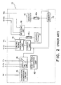
- the tap control circuit 10 comprises a producing section 21 and a controlling section 22.
- the producing section 21 comprises first through N-th producing units 21-1, 21-2, ..., and 21-N for producing the first through the N-th controllable tap gains W1 to WN.
- the first through the N-th producing units 21-1 to 21-N are connected to the first through the N-th multipliers 18-1 to 18-N through first to N-th taps 23-1, 23-2, ..., and 23-N, respectively.
- the controlling section 22 supplies the first through the N-th producing units 21-1, 21-2, ..., and 21-N with a control parameter M which is representative of a varying rate of the first through the N-th controllable tap gains W1 to WN.
- the control parameter may alternatively be called a step size.
- the controlling section 22 delivers first through N-th reset signals C1 to CN and first through N-th control signals V1 to VN to the first through the N-th producing units 21-1 to 21-N in accordance with the first through the N-th controllable tap gains W1 to WN in order to select selected ones of the first through the N-th controllable tap gains W1 to WN.
- the first producing unit 21-1 comprises first through third unit multipliers 31 to 33, a producing unit adder 34, and a producing unit register (R) 35.
- each of the second through the N-th producing circuits 21-2 to 21-N comprises similar parts, which are depicted in the first producing circuit 21-1 alone.
- the first unit multiplier 31 receives the received signal and the error signal and multiplies the received signal by the error signal to supply a first unit multiplied signal to the second unit multiplier 32. Supplied with the control parameter M, the second unit multiplier 32 multiplies the first unit multiplied signal by the control parameter M to supply second unit multiplied signal to the unit adder 34.
- the unit register 35 gives a delay of the predetermined time (1/f) to a signal supplied thereto.
- the unit register 35 supplies a producing unit delayed signal to the unit adder 34 and the third unit multiplier 33.
- the unit adder 34 adds the second unit multiplied signal to the unit delayed signal to supply a producing unit sum signal to the unit register 35.
- the third unit multiplier 33 multiplies the unit delayed signal by the first control signal V1 to deliver a third unit multiplied signal as the first controllable tap gain W1 to the first filter multiplier 18-1 through the first tap 23-1.
- the second through the N-th producing units 21-2 to 21-N receive the first through the (N-1)-th delayed signals, respectively, and receive the error signal.
- the second through the N-th producing units 21-2 to 21-N produce the second through the N-th controllable tap gains W2 to WN in a similar manner as described in connection with the first producing unit 18-1.
- the controlling section 22 comprises first and second memories 41 and 42.
- the first memory 41 comprises a first tap number area (not shown) for memorizing first through N-th tap numbers and a first initial information area (not shown) for memorizing first through N-th initial information signals in one-to-one correspondence to the first through the N-th tap numbers.
- Each of the first through the N-th initial information signals may represent one of a logic zero and a logic one level.
- the first through the N-th tap numbers will be called first through N-th effective tap numbers.
- the first through the N-th tap numbers will be called first through N-th invalid tap numbers.
- first through K-th predetermined ones of the first through the N-th tap numbers are memorized as first through K-th effective tap numbers in the first memory 41, where K represents a positive number which is less than N and is not less than one.
- Remaining ones of the first through the N-th tap numbers are memorized as first through P-th invalid tap numbers in the first memory 41, where P is a positive number which is equal to N - K.
- the second memory 42 is for memorizing the first through the P-th invalid tap numbers in an ascending order in a form of a queue.
- first and second switches 41a and 42a are closed.
- the first through the P-th invalid tap numbers are read out of the second memory 42 to be supplied to a third memory 43 which is operable in a first-in-first-out fashion.
- the first through the N-th tap numbers and first through the N-th initial information signals are read out of the first memory 41 to be supplied to a control signal producing unit 44.
- control parameter M is supplied from a parameter generating circuit 45 to the first through the N-th producing units 22-1 to 22-N when the echo canceller 11 is put into operation.
- the control signal producing unit 44 Responsive to the first through the N-th tap numbers and first through the N-th initial information signals, the control signal producing unit 44 produces the first through the N-th control signals V1 to VN, which represent one of the logic zero and the logic one levels in conjunction with the first through the N-th initial information signals.
- the first control signal V1 represents the logic zero level when the first initial information signal has the logic zero level.
- the third unit multiplier 33 multiplies the unit delayed signal by the first control signal V1.
- the third unit multiplier 33 produces the first controllable tap gain W1 of a zero level.
- the first through the N-th controllable tap gains W1 to WN are delivered to a minimum detecting unit 46.
- the detecting unit 46 periodically detects whether or not one of the first through the N-th first through the N-th controllable tap gains W1 to WN is coincident with a prescribed value which may be a positive value equal to a smallest one among absolute values of the first through the N-th controllable tap gains W1 to WN.
- the detecting unit 46 produces a k-th tap signal representative of a k-th effective tap number when the k-th controllable tap gain Wk is coincident with the prescribed value, where k is a positive number selected between 1 and K.
- the k-th tap signal is supplied from the detecting unit 46 to the third memory 43 and a control unit 47.
- the first invalid tap number is read out of the third memory 43 as an effective tap number and is supplied as the effective tap number to the control unit 47 and a switching unit 48.
- the third memory 43 memorizes the k-th tap number as a k-th invalid tap number behind the P-th invalid tap number in the first-in-first-out fashion.
- the control unit 47 controls the control signal producing unit 44 so that the control signal producing unit 44 makes a k-th control signal Vk have the logic zero level in correspondence to the k-th tap number and makes a p-th control signal Vp have the logic one level in correspondence with the effective tap number, where p is a positive number between 1 and P.
- the switching unit 48 is responsive to the effective tap number and connects a reset signal generating unit 49 to a p-th producing unit 21-p corresponding to the effective tap number to supply a p-th reset signal to the p-th producing unit.
- the controlling section 22 produces the first through the N-th control signals V1 to VN and controls the producing section 21 to select the selected ones of the first through the N-th controllable tap gains W1 to WN as first through K-th selected tap gains so that the echo canceller 11 filters the received signal into the filtered signal as desired.
- the illustrated tap control circuit does not vary the control parameter M in accordance with the first through the N-th controllable tap gains W1 to WN on selecting the first through the K-th selected tap gains from the first through the N-th controllable tap gains W1 to WN. Therefore, it is difficult to rapidly select the first through the K-th selected tap gains from the first through the N-th controllable tap gains W1 to WN.
- the illustrated tap control circuit is different from the tap control circuit 10 illustrated with reference to Fig. 2 and is therefore designated afresh by a reference numeral 50.
- the tap control circuit 50 comprises similar parts which are designated by like reference numerals and are operable with likewise named and denoted signals. It should be noted that the tap control circuit 50 controls the echo canceller 11 described in connection with Fig. 1 instead of the tap control circuit 10.
- the tap control circuit 50 further comprises first and second parameter generating units 51 and 52.
- the first parameter generating unit 51 generates a first parameter ⁇ 1.
- the second parameter generating unit 52 generates a second parameter ⁇ 2 which is greater than the first parameter ⁇ 1.
- the first parameter ⁇ 1 may be equal to 2 ⁇ 7.
- the second parameter ⁇ 2 may be equal to 2 ⁇ 1.
- the first through the second switches 41a and 42a are closed when the echo canceller 11 (Fig. 1) is put into operation.
- the first through the N-th tap numbers and the first through the N-th initial information signals are supplied from the first memory 41 to the control signal producing unit 44.
- the first through the P-th invalid tap numbers are delivered from the second memory 42 to the third memory 43.
- the control signal producing unit 44 produces the first through the N-th control signals V1 to VN in accordance with the first through the N-th tap numbers and the first through the N-th initial information signals to supply the first through the N-th control signals V1 to VN to the first through the N-th producing units 21-1 to 21-N (Fig. 1).
- the controllable tap gains W1 to WN are supplied from the first through the N-th producing units 21-1 to 21-N (Fig. 1) to a maximum detecting unit 55.
- the maximum detecting unit 55 periodically detects whether or not one of the first through the N-th controllable tap gains W1 to WN is coincident with a predetermined value.
- the predetermined value may be a largest one among absolute values of the first through the N-th controllable tap gains W1 to WN.
- the maximum detecting unit 55 produces a maximum tap signal representative of a n-th tap number, where n is one of the positive integer N.
- the maximum detecting unit 55 supplies the maximum tap signal to a second judging unit 56 and a buffer memory 57.
- the maximum tap signal is memorized in the buffer memory 57 as a buffered tap number. This is because the maximum tap signal is periodically supplied from the maximum detecting unit 55 to the buffer memory 57.
- the buffer memory 57 memorizes a plurality of buffered tap numbers which may be different from each other.
- the buffer memory 57 memorizes the buffered tap numbers which are equal in number to a predetermined number. When the buffer memory 57 memorizes the buffered tap numbers of the predetermined number, the buffer memory 57 outputs the buffered tap numbers to the first judging unit 54.
- the predetermined number is, for example, 80.
- the first judging unit 54 first counts specific tap numbers which are equal to each other among the buffered tap numbers.
- the first judging unit 54 produces a count signal which is representative of the number of the specific tap numbers. Namely, the count signal has a variable level depending on the number of the specific tap numbers.
- the first judging unit 54 judges whether or not the level of the count signal is not less than a predetermined threshold level or number which is not greater than the predetermined number. For example, the predetermined threshold level is specified by a count of seventy-two.
- the first judging unit 54 produces a driving signal to select the second parameter generating unit 52.
- the first judging unit 54 produces the driving signal when the number of the specific tap numbers is not less than the predetermined threshold level.
- the first switching circuit 53 connects the second parameter generating unit 52 to the first through the N-th producing units 21-1 to 21-N to supply the second parameter ⁇ 2 as the control parameter M to the first through the N-th producing units 21-1 to 21-N.
- the driving signal is supplied further to third and fourth switches 58a and 58b to close the third and the fourth switches 58a and 58b.
- the minimum detecting unit 46 supplies the k-th tap signal to the third memory 43.
- the third memory memorizes the k-th tap number behind the P-th invalid tap number in the first-in-first-out fashion and outputs the first invalid tap number to supply the first invalid tap number to the second judging unit 56.
- the second judging unit 56 is supplied with the maximum tap signal.
- the second judging unit 56 produces a switching signal to supply the switching signal to a second switching circuit 59. n - K ⁇ S1 ⁇ n + K, where S1 represents the first invalid tap number.
- the second switching circuit 59 connects the third memory 43 to the control unit 47 through the third switch 58a to supply the first invalid tap number as the effective tap number to the control unit 47.
- the second switching circuit 59 supplies the first invalid tap number to the third memory 43 when the switching signal is not supplied to the second switching circuit 59.
- the third memory memorizes the first invalid tap number behind the k-th invalid tap number in the first-in-first-out fashion and outputs the second invalid tap number to supply the second invalid tap number to the second judging unit 56.
- the second judging unit 56 judges the relationship among the second invalid tap number, the n-th tap number, and the positive integer N in a similar manner described in connection with the inequality (1).
- the k-th tap number signal and the effective tap number signal are supplied to control unit 47 after the third and fourth switches 58a and 58b are closed, respectively, namely, after the second parameter ⁇ 2 is supplied as the control parameter M to the first through the N-th producing units 21-1 to 21-N.
- the control unit 47 controls the control signal producing unit 44 in a manner similar to that described in conjunction with Fig. 2.
- the control signal producing unit 44 makes the k-th control signal Vk have the logic zero level in correspondence to the k-th tap number and makes the p-th control signal Vp have the logic one level in correspondence to the effective tap number.
- the effective tap number signal is supplied to the switching unit 48 through the third switch 58a. Supplied with the effective tap number signal, the switching unit 48 delivers the p-th reset signal from the reset signal generating unit 49 to the p-th producing unit 21-p as described in connection with Fig. 2.
- the first judging unit 54, the second detecting circuit 55, and the buffer memory 57 are operable collectively as a selecting section for selecting one of the first and the second parameter generating circuits 51 and 52 to selectively supply the first and the second parameter ⁇ 1 and ⁇ 2 as the control parameter M in accordance with the first through the N-th controllable tap gains W1 to WN.
Landscapes
- Filters That Use Time-Delay Elements (AREA)
- Cable Transmission Systems, Equalization Of Radio And Reduction Of Echo (AREA)
- Soundproofing, Sound Blocking, And Sound Damping (AREA)
Claims (6)
- Anzapfsteuerschaltung (50) zur Verwendung in einem adaptiven Filter (11) zum Filtern eines empfangenen Signals (17) in ein gefiltertes Signal (13) entsprechend einer ersten bis N-ten regelbaren Anzapfverstärkung (W₁, ..., WN), wobei N eine positive ganze Zahl darstellt, die nicht kleiner als eins ist, wobei die Anzapfsteuerschaltung aufweist: eine Erzeugungseinrichtung (21-1, ..., 21-N) zum Erzeugen der ersten bis N-ten regelbaren Anzapfverstärkung in Abhängigkeit von dem gefilterten Signal (13) und einem Regelparameter (M) und eine Steuereinrichtung (50) zum Steuern der Erzeugungseinrichtung, um gewählte Verstärkungen der ersten bis N-ten regelbaren Anzapfverstärkung entsprechend der ersten bis N-ten regelbaren Anzapfverstärkung zu wählen, wobei die Steuereinrichtung aufweist:
eine erste Erzeugungseinrichtung (51) zum Erzeugen eines ersten Parameters;
dadurch gekennzeichnet, daß die Steuereinrichtung ferner aufweist:
eine zweite Erzeugungseinrichtung (52) zum Erzeugen eines zweiten Parameters, der größer ist als der erste Parameter; und
eine Wähleinrichtung (53, 54, 55, 57) zum Wählen der ersten (51) oder der zweiten (52) Erzeugungseinrichtung, um den ersten und den zweiten Parameter selektiv entsprechend der ersten bis N-ten regelbaren Anzapfverstärkungen (W1, ..., WN) als den Regelparameter (M) an die Erzeugungseinrichtung (21-1, ..., 21-N) zu liefern. - Anzapfsteuerschaltung nach Anspruch 1, bei der die Wähleinrichtung (53-55, 57) die erste Erzeugungseinrichtung (51) wählt, um den ersten Parameter an die Erzeugungseinrichtung zu liefern, wenn das adaptive Filter in Betrieb gesetzt wird.
- Anzapfsteuerschaltung nach Anspruch 2, bei der eine Wähleinrichtung (53-55, 57) aufweist:
eine erste Ermittlungseinrichtung (55) zum periodischen Ermitteln, ob eine der ersten bis N-ten regelbaren Anzapfverstärkungen mit einem vorbestimmten Wert übereinstimmt, wobei die erste Ermittlungseinrichtung ein erstes Anzapfsignal erzeugt, wenn eine der ersten bis N-ten regelbaren Anzapfverstärkungen mit dem vorbestimmten Wert übereinstimmt;
eine Zähleinrichtung (54) zum Zählen des ersten Anzapfsignals, um ein Zählsignal mit einem variablen Wert zu erzeugen; und
eine Entscheidungseinrichtung (56) zum Beurteilen, ob der Wert des Zählsignals größer ist als ein vorbestimmter Schwellenwert oder nicht, wobei die Entscheidungseinrichtung ein Treibsignal erzeugt, um die zweite Erzeugungseinrichtung zu wählen, wenn der Wert des Zählsignals größer ist als der vorbestimmte Schwellenwert. - Anzapfsteuerschaltung nach Anspruch 3, bei der der vorbestimmte Wert ein größter Wert unter absoluten Werten der ersten bis N-ten regelbaren Anzapfverstärkungen ist.
- Anzapfsteuerschaltung nach Anspruch 3 oder 4, wobei die Erzeugungseinrichtung (21-1, ..., 21-N) jeweils eine erste bis N-te regelbare Anzapfverstärkung über eine erste bis N-te Anzapfung (23-1, ..., 23-N) an das adaptive Filter liefert, wobei das erste Anzapfsignal (W₁) eine erste Anzapfung (23-1) der ersten bis N-ten Anzapfung darstellt, wobei die Steuereinrichtung aufweist:
eine zweite Ermittlungseinrichtung (46), die auf das Treibsignal anspricht, zum periodischen Ermitteln, ob eine der ersten bis N-ten regelbaren Anzapfverstärkungen mit einem vorgeschriebenen Wert übereinstimmt, wobei die zweite Ermittlungseinrichtung ein zweites Anzapfsignal erzeugt, wenn die zuletzt erwähnte Verstärkung der ersten bis N-ten regelbaren Anzapfverstärkung mit dem vorgeschriebenen Wert übereinstimmt, wobei das zweite Anzapfsignal eine zweite Anzapfung der ersten bis N-ten Anzapfung darstellt;
eine dritte Erzeugungseinrichtung (43) zum Erzeugen eines dritten Signals der ersten bis N-ten Anzapfung als ein drittes Anzapfsignal;
eine Wegwahleinrichtung (56, 59) zum Durchlassen des dritten Anzapfsignals als ein viertes Anzapfsignal in Abhängigkeit von dem ersten Anzapfsignal und dem dritten Anzapfsignal; und
eine Bestimmungseinrichtung (47) zum Bestimmen der gewählten Verstärkungen der ersten bis N-ten regelbaren Anzapfverstärkungen als erste bis K-te gewählte Anzapfverstärkung entsprechend dem zweiten und dem vierten Anzapfsignal, wobei K eine positive Zahl darstellt, die kleiner ist als die positive ganze Zahl N und nicht kleiner ist als eins. - Anzapfsteuerschaltung nach Anspruch 5, bei der der vorgeschriebene Wert ein positiver Wert ist, der gleich einem kleinsten unter den absoluten Werten der ersten bis N-ten regelbaren Anzapfverstärkungen ist.
Applications Claiming Priority (2)
| Application Number | Priority Date | Filing Date | Title |
|---|---|---|---|
| JP2066401A JP2540974B2 (ja) | 1990-03-15 | 1990-03-15 | アダプティブ・フィルタ適応化方法及び装置 |
| JP66401/90 | 1990-03-15 |
Publications (3)
| Publication Number | Publication Date |
|---|---|
| EP0446917A2 EP0446917A2 (de) | 1991-09-18 |
| EP0446917A3 EP0446917A3 (en) | 1992-02-26 |
| EP0446917B1 true EP0446917B1 (de) | 1995-09-06 |
Family
ID=13314752
Family Applications (1)
| Application Number | Title | Priority Date | Filing Date |
|---|---|---|---|
| EP91103940A Expired - Lifetime EP0446917B1 (de) | 1990-03-15 | 1991-03-14 | Anzapfverstärkungsregulierungsschaltung mit hoher Geschwindigkeit in einem adaptiven Filter |
Country Status (6)
| Country | Link |
|---|---|
| US (1) | US5218560A (de) |
| EP (1) | EP0446917B1 (de) |
| JP (1) | JP2540974B2 (de) |
| AU (1) | AU644854B2 (de) |
| CA (1) | CA2038305C (de) |
| DE (1) | DE69112677T2 (de) |
Families Citing this family (8)
| Publication number | Priority date | Publication date | Assignee | Title |
|---|---|---|---|---|
| JP2540974B2 (ja) | 1990-03-15 | 1996-10-09 | 日本電気株式会社 | アダプティブ・フィルタ適応化方法及び装置 |
| JP2541378B2 (ja) * | 1990-12-27 | 1996-10-09 | 日本電気株式会社 | アダプティブ・フィルタによる未知システム近似の方法及び装置 |
| JP2569979B2 (ja) * | 1991-01-31 | 1997-01-08 | 日本電気株式会社 | システム特性推定方法及び装置 |
| JP2581458B2 (ja) * | 1994-06-15 | 1997-02-12 | 日本電気株式会社 | アダプティブフィルタの適応化方法及び装置 |
| JP2643852B2 (ja) * | 1994-08-31 | 1997-08-20 | 日本電気株式会社 | エコーキャンセラ |
| JP3204151B2 (ja) * | 1997-02-13 | 2001-09-04 | 日本電気株式会社 | 適応フィルタ |
| US6243428B1 (en) * | 1997-06-11 | 2001-06-05 | Ericsson Inc. | Method and apparatus for band-adaptive demodulation |
| JP5473635B2 (ja) * | 2010-01-28 | 2014-04-16 | クラリオン株式会社 | ステレオ信号定位補正装置 |
Family Cites Families (4)
| Publication number | Priority date | Publication date | Assignee | Title |
|---|---|---|---|---|
| JPS61116434A (ja) * | 1984-11-12 | 1986-06-03 | Fujitsu Ltd | 自動等化方式 |
| US4843583A (en) * | 1985-10-15 | 1989-06-27 | Rockwell International Corporation | Nonlinear adaptive filter |
| JP3011948B2 (ja) * | 1989-07-31 | 2000-02-21 | パイオニア株式会社 | ディジタル等化器 |
| JP2540974B2 (ja) | 1990-03-15 | 1996-10-09 | 日本電気株式会社 | アダプティブ・フィルタ適応化方法及び装置 |
-
1990
- 1990-03-15 JP JP2066401A patent/JP2540974B2/ja not_active Expired - Lifetime
-
1991
- 1991-03-14 DE DE69112677T patent/DE69112677T2/de not_active Expired - Fee Related
- 1991-03-14 EP EP91103940A patent/EP0446917B1/de not_active Expired - Lifetime
- 1991-03-14 CA CA002038305A patent/CA2038305C/en not_active Expired - Fee Related
- 1991-03-15 US US07/670,100 patent/US5218560A/en not_active Expired - Fee Related
- 1991-03-15 AU AU73528/91A patent/AU644854B2/en not_active Ceased
Also Published As
| Publication number | Publication date |
|---|---|
| US5218560A (en) | 1993-06-08 |
| DE69112677T2 (de) | 1996-02-01 |
| AU7352891A (en) | 1991-09-19 |
| EP0446917A3 (en) | 1992-02-26 |
| EP0446917A2 (de) | 1991-09-18 |
| CA2038305C (en) | 1996-02-27 |
| JPH03266516A (ja) | 1991-11-27 |
| JP2540974B2 (ja) | 1996-10-09 |
| AU644854B2 (en) | 1993-12-23 |
| DE69112677D1 (de) | 1995-10-12 |
| CA2038305A1 (en) | 1991-09-16 |
Similar Documents
| Publication | Publication Date | Title |
|---|---|---|
| JP2953132B2 (ja) | データ受信装置の等化器 | |
| JP2508574B2 (ja) | 多チャンネルエコ―除去装置 | |
| EP0561133B1 (de) | Mehrkanalsechokompensation mit adaptiven Filtern welche auswählbare Koeffizientvektoren haben | |
| US4791390A (en) | MSE variable step adaptive filter | |
| US4349889A (en) | Non-recursive filter having adjustable step-size for each iteration | |
| US5402445A (en) | Decision feedback equalizer | |
| EP0727882B1 (de) | Echokompensation und -unterdrückung | |
| GB2135558A (en) | Improvements in or relating to delay estimation | |
| GB2214386A (en) | Signal equaliser | |
| EP0446917B1 (de) | Anzapfverstärkungsregulierungsschaltung mit hoher Geschwindigkeit in einem adaptiven Filter | |
| CA2079292A1 (en) | Fast response matched filter receiver with decision feedback equalizer | |
| CA2198677C (en) | Adaptive filter with disabling circuit for fast tap weight convergence | |
| JPH04334211A (ja) | データ受信装置 | |
| CA2076710C (en) | Channel impulse response estimator for a system having a rapidly fluctuating channel characteristic | |
| US4574166A (en) | Tandem adaptive filter arrangement | |
| US3798560A (en) | Adaptive transversal equalizer using a time-multiplexed second-order digital filter | |
| EP0688099B1 (de) | Zur Restechounterdrückung mit hoher Geschwindigkeit fähiges adaptives Filter | |
| JPS59147521A (ja) | タンデム適応フイルタ | |
| US5073942A (en) | Sound field control apparatus | |
| US4233683A (en) | Cascaded equalizer technique | |
| US7580453B2 (en) | Method and apparatus for equalization | |
| US3708766A (en) | Automatic equalizer and method of operation therefor | |
| EP0117626A2 (de) | Adaptive Filter | |
| EP0253583A2 (de) | Adaptives digitales Filter | |
| JP2000091965A (ja) | 等化器及び等化方法 |
Legal Events
| Date | Code | Title | Description |
|---|---|---|---|
| PUAI | Public reference made under article 153(3) epc to a published international application that has entered the european phase |
Free format text: ORIGINAL CODE: 0009012 |
|
| 17P | Request for examination filed |
Effective date: 19910410 |
|
| AK | Designated contracting states |
Kind code of ref document: A2 Designated state(s): DE FR GB |
|
| PUAL | Search report despatched |
Free format text: ORIGINAL CODE: 0009013 |
|
| AK | Designated contracting states |
Kind code of ref document: A3 Designated state(s): DE FR GB |
|
| 17Q | First examination report despatched |
Effective date: 19941013 |
|
| GRAA | (expected) grant |
Free format text: ORIGINAL CODE: 0009210 |
|
| AK | Designated contracting states |
Kind code of ref document: B1 Designated state(s): DE FR GB |
|
| REF | Corresponds to: |
Ref document number: 69112677 Country of ref document: DE Date of ref document: 19951012 |
|
| ET | Fr: translation filed | ||
| PLBE | No opposition filed within time limit |
Free format text: ORIGINAL CODE: 0009261 |
|
| STAA | Information on the status of an ep patent application or granted ep patent |
Free format text: STATUS: NO OPPOSITION FILED WITHIN TIME LIMIT |
|
| 26N | No opposition filed | ||
| REG | Reference to a national code |
Ref country code: GB Ref legal event code: IF02 |
|
| PGFP | Annual fee paid to national office [announced via postgrant information from national office to epo] |
Ref country code: FR Payment date: 20020312 Year of fee payment: 12 |
|
| PGFP | Annual fee paid to national office [announced via postgrant information from national office to epo] |
Ref country code: GB Payment date: 20020313 Year of fee payment: 12 |
|
| PGFP | Annual fee paid to national office [announced via postgrant information from national office to epo] |
Ref country code: DE Payment date: 20020327 Year of fee payment: 12 |
|
| PG25 | Lapsed in a contracting state [announced via postgrant information from national office to epo] |
Ref country code: GB Free format text: LAPSE BECAUSE OF NON-PAYMENT OF DUE FEES Effective date: 20030314 |
|
| PG25 | Lapsed in a contracting state [announced via postgrant information from national office to epo] |
Ref country code: DE Free format text: LAPSE BECAUSE OF NON-PAYMENT OF DUE FEES Effective date: 20031001 |
|
| GBPC | Gb: european patent ceased through non-payment of renewal fee |
Effective date: 20030314 |
|
| PG25 | Lapsed in a contracting state [announced via postgrant information from national office to epo] |
Ref country code: FR Free format text: LAPSE BECAUSE OF NON-PAYMENT OF DUE FEES Effective date: 20031127 |
|
| REG | Reference to a national code |
Ref country code: FR Ref legal event code: ST |