EP0446959A2 - Méthode pour la manufacture d'une tige essentiellement cylindrique avec bras de centrage passant vers la tige à une pièce - Google Patents
Méthode pour la manufacture d'une tige essentiellement cylindrique avec bras de centrage passant vers la tige à une pièce Download PDFInfo
- Publication number
- EP0446959A2 EP0446959A2 EP91105233A EP91105233A EP0446959A2 EP 0446959 A2 EP0446959 A2 EP 0446959A2 EP 91105233 A EP91105233 A EP 91105233A EP 91105233 A EP91105233 A EP 91105233A EP 0446959 A2 EP0446959 A2 EP 0446959A2
- Authority
- EP
- European Patent Office
- Prior art keywords
- centering arm
- contact surfaces
- shaft
- area
- clamping device
- Prior art date
- Legal status (The legal status is an assumption and is not a legal conclusion. Google has not performed a legal analysis and makes no representation as to the accuracy of the status listed.)
- Withdrawn
Links
Images
Classifications
-
- B—PERFORMING OPERATIONS; TRANSPORTING
- B23—MACHINE TOOLS; METAL-WORKING NOT OTHERWISE PROVIDED FOR
- B23P—METAL-WORKING NOT OTHERWISE PROVIDED FOR; COMBINED OPERATIONS; UNIVERSAL MACHINE TOOLS
- B23P15/00—Making specific metal objects by operations not covered by a single other subclass or a group in this subclass
-
- B—PERFORMING OPERATIONS; TRANSPORTING
- B21—MECHANICAL METAL-WORKING WITHOUT ESSENTIALLY REMOVING MATERIAL; PUNCHING METAL
- B21K—MAKING FORGED OR PRESSED METAL PRODUCTS, e.g. HORSE-SHOES, RIVETS, BOLTS OR WHEELS
- B21K1/00—Making machine elements
- B21K1/76—Making machine elements elements not mentioned in one of the preceding groups
-
- B—PERFORMING OPERATIONS; TRANSPORTING
- B23—MACHINE TOOLS; METAL-WORKING NOT OTHERWISE PROVIDED FOR
- B23Q—DETAILS, COMPONENTS, OR ACCESSORIES FOR MACHINE TOOLS, e.g. ARRANGEMENTS FOR COPYING OR CONTROLLING; MACHINE TOOLS IN GENERAL CHARACTERISED BY THE CONSTRUCTION OF PARTICULAR DETAILS OR COMPONENTS; COMBINATIONS OR ASSOCIATIONS OF METAL-WORKING MACHINES, NOT DIRECTED TO A PARTICULAR RESULT
- B23Q1/00—Members which are comprised in the general build-up of a form of machine, particularly relatively large fixed members
- B23Q1/03—Stationary work or tool supports
-
- B—PERFORMING OPERATIONS; TRANSPORTING
- B23—MACHINE TOOLS; METAL-WORKING NOT OTHERWISE PROVIDED FOR
- B23Q—DETAILS, COMPONENTS, OR ACCESSORIES FOR MACHINE TOOLS, e.g. ARRANGEMENTS FOR COPYING OR CONTROLLING; MACHINE TOOLS IN GENERAL CHARACTERISED BY THE CONSTRUCTION OF PARTICULAR DETAILS OR COMPONENTS; COMBINATIONS OR ASSOCIATIONS OF METAL-WORKING MACHINES, NOT DIRECTED TO A PARTICULAR RESULT
- B23Q16/00—Equipment for precise positioning of tool or work into particular locations not otherwise provided for
- B23Q16/02—Indexing equipment
- B23Q16/08—Indexing equipment having means for clamping the relatively movable parts together in the indexed position
-
- Y—GENERAL TAGGING OF NEW TECHNOLOGICAL DEVELOPMENTS; GENERAL TAGGING OF CROSS-SECTIONAL TECHNOLOGIES SPANNING OVER SEVERAL SECTIONS OF THE IPC; TECHNICAL SUBJECTS COVERED BY FORMER USPC CROSS-REFERENCE ART COLLECTIONS [XRACs] AND DIGESTS
- Y10—TECHNICAL SUBJECTS COVERED BY FORMER USPC
- Y10T—TECHNICAL SUBJECTS COVERED BY FORMER US CLASSIFICATION
- Y10T29/00—Metal working
- Y10T29/49—Method of mechanical manufacture
- Y10T29/49636—Process for making bearing or component thereof
- Y10T29/49643—Rotary bearing
- Y10T29/49647—Plain bearing
- Y10T29/49648—Self-adjusting or self-aligning, including ball and socket type, bearing and component making
-
- Y—GENERAL TAGGING OF NEW TECHNOLOGICAL DEVELOPMENTS; GENERAL TAGGING OF CROSS-SECTIONAL TECHNOLOGIES SPANNING OVER SEVERAL SECTIONS OF THE IPC; TECHNICAL SUBJECTS COVERED BY FORMER USPC CROSS-REFERENCE ART COLLECTIONS [XRACs] AND DIGESTS
- Y10—TECHNICAL SUBJECTS COVERED BY FORMER USPC
- Y10T—TECHNICAL SUBJECTS COVERED BY FORMER US CLASSIFICATION
- Y10T29/00—Metal working
- Y10T29/49—Method of mechanical manufacture
- Y10T29/49636—Process for making bearing or component thereof
- Y10T29/49705—Coating or casting
-
- Y—GENERAL TAGGING OF NEW TECHNOLOGICAL DEVELOPMENTS; GENERAL TAGGING OF CROSS-SECTIONAL TECHNOLOGIES SPANNING OVER SEVERAL SECTIONS OF THE IPC; TECHNICAL SUBJECTS COVERED BY FORMER USPC CROSS-REFERENCE ART COLLECTIONS [XRACs] AND DIGESTS
- Y10—TECHNICAL SUBJECTS COVERED BY FORMER USPC
- Y10T—TECHNICAL SUBJECTS COVERED BY FORMER US CLASSIFICATION
- Y10T29/00—Metal working
- Y10T29/49—Method of mechanical manufacture
- Y10T29/49826—Assembling or joining
- Y10T29/4984—Retaining clearance for motion between assembled parts
-
- Y—GENERAL TAGGING OF NEW TECHNOLOGICAL DEVELOPMENTS; GENERAL TAGGING OF CROSS-SECTIONAL TECHNOLOGIES SPANNING OVER SEVERAL SECTIONS OF THE IPC; TECHNICAL SUBJECTS COVERED BY FORMER USPC CROSS-REFERENCE ART COLLECTIONS [XRACs] AND DIGESTS
- Y10—TECHNICAL SUBJECTS COVERED BY FORMER USPC
- Y10T—TECHNICAL SUBJECTS COVERED BY FORMER US CLASSIFICATION
- Y10T29/00—Metal working
- Y10T29/49—Method of mechanical manufacture
- Y10T29/49972—Method of mechanical manufacture with separating, localizing, or eliminating of as-cast defects from a metal casting [e.g., anti-pipe]
- Y10T29/49973—Compressing ingot while still partially molten
-
- Y—GENERAL TAGGING OF NEW TECHNOLOGICAL DEVELOPMENTS; GENERAL TAGGING OF CROSS-SECTIONAL TECHNOLOGIES SPANNING OVER SEVERAL SECTIONS OF THE IPC; TECHNICAL SUBJECTS COVERED BY FORMER USPC CROSS-REFERENCE ART COLLECTIONS [XRACs] AND DIGESTS
- Y10—TECHNICAL SUBJECTS COVERED BY FORMER USPC
- Y10T—TECHNICAL SUBJECTS COVERED BY FORMER US CLASSIFICATION
- Y10T29/00—Metal working
- Y10T29/49—Method of mechanical manufacture
- Y10T29/4998—Combined manufacture including applying or shaping of fluent material
- Y10T29/49982—Coating
- Y10T29/49984—Coating and casting
Definitions
- the present invention relates to a method for producing an essentially cylindrical shaft with a centering arm which integrally merges into the shaft and which can be fixed very precisely against a clamping device with a groove for receiving the centering arm, according to the preamble of patent claim 1.
- a shaft with a centering arm which integrally merges into the shaft is a common means for the highly precise positioning of any object, in particular a workpiece to be machined, in relation to a clamping device with a groove for receiving the centering arm.
- such a shaft is made from high-quality machine steel.
- the fine machining of the centering arm in the area of its contact surfaces with the groove of the clamping device is complex and therefore cost-intensive.
- the present invention has for its object to develop a method of the type mentioned in such a way that the shaft with its centering arm which integrally merges into the shaft is easier to manufacture, while still positioning the shaft with the centering arm with high precision the jig must be guaranteed.
- the shaft is first cast from a plastically deformable, relatively soft material, which can be done by metal die casting for the materials light metals and zinc alloy.
- the shaft can also be made of light metal, a zinc alloy or a sintered material. Even if high accuracies are observed, only a casting accuracy of the order of a few hundredths of a millimeter is achieved.
- the shaft, with its centering arm integrally passing into it is pressed into a calibration tool which plastically deforms the centering arm with the groove of the clamping device, at least in the area of the contact surfaces. With this plastic deformation, an accuracy of the contact surfaces in the micrometer range is achieved and furthermore a compression of the material in the region of the contact surfaces is achieved.
- the centering arm is preferably further solidified in the area of its contact surfaces by a surface treatment.
- the surface treatment can be the application of a metallic surface coating that is hard compared to the material of the centering arm or by anodizing events with little centering.
- the surface is preferably made of nickel.
- the shaft is placed in a container which contains a large number of small parts, which can be metal balls, for example, which each have the same or different diameters.
- the container is then moved for a certain period of time, so that the balls continuously hit the surface of the centering arm as a result of the movement. This results in a compression of the material on the surface of the centering arm and thus a solidification of the material.
- a certain surface structure is also obtained from a large number of small craters. This surface structure is very advantageous because the small craters can pick up smaller dirt particles without impairing the possible clamping accuracy.
- a method related to ball polishing is shot peening of the centering arm, whereby the surface experiences a smoothing of the grain boundaries and a strain hardening, especially when using an aluminum die casting.
- the type of treatment eliminates unwanted, flaky surface structures of an untreated die-cast aluminum.
- Another advantage of a non-nickel-plated die-cast aluminum surface in the area of the contact surface of the centering arm is that, when dirty, small particles that get between the centering arm and the clamping device are pressed into the aluminum material. Up to a certain degree of contamination, the positioning accuracy or repetition accuracy is not impaired.
- aluminum or an aluminum alloy is selected as the material for the shaft and the centering arm.
- Aluminum has proven to be particularly suitable for calibration or plastic deformation by being pressed into a calibration tool. Furthermore, when the shaft is manufactured with the centering arm made of aluminum, a desired reduction in weight is achieved compared to the weight that would have to be accepted when manufactured from a machine steel. If aluminum or an aluminum alloy is used, anodizing will also bring the desired surface hardness as a surface treatment.
- the preferred casting accuracy for the centering arm in the area of its contact surfaces is approximately 10 to 50 micrometers, preferably approximately 20 micrometers, the shape accuracy that can be achieved by the subsequent calibration, based on such casting accuracies, being in the range of 1 to 5 micrometers, usually approximately 3 micrometers.
- the specified casting accuracies can still be achieved with tolerable effort in the manufacture of the mold and the implementation of aluminum die casting or other casting.
- a particularly hard surface that is also manufacturing-technical easy to apply with die-cast aluminum, is achieved by nickel plating, anodizing or by mechanical surface treatment such as ball polishing or shot peening.
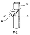
- the article produced by the process according to the invention and shown in perspective in the single figure comprises an essentially cylindrical shaft 42 with a centering arm 43 which extends integrally into the cylindrical shaft and extends at right angles to this centering arm 43 also with regard to its rotational position particularly precisely in relation to a known clamping device for such shanks with a groove for receiving the centering arm.
- the shaft 42 effects an axial alignment and the centering arm 43 performs a rotation angle alignment.
- the shaft 42 is cast together with the centering arm 43 in one piece in high-pressure aluminum casting.
- the shaft is then deep-drawn and the centering arm 43 is calibrated in the area of the desired contact surfaces 44, 45 by pressing it into a calibration tool (not shown), with a plastic deformation of the centering arm 43 in the area of the contact surfaces 44, 45 and surface compaction in this area.
- the shaft 42 is nickel-plated together with the centering arm 43 or with one other suitable, hard surface coating.
Landscapes
- Engineering & Computer Science (AREA)
- Mechanical Engineering (AREA)
- Powder Metallurgy (AREA)
- Forging (AREA)
- Feeding Of Workpieces (AREA)
- Jigs For Machine Tools (AREA)
- Sampling And Sample Adjustment (AREA)
- Pallets (AREA)
- Electroplating Methods And Accessories (AREA)
Applications Claiming Priority (4)
| Application Number | Priority Date | Filing Date | Title |
|---|---|---|---|
| DE3732206 | 1987-09-24 | ||
| DE19873732206 DE3732206A1 (de) | 1987-09-24 | 1987-09-24 | Verfahren zum herstellen eines bezueglich eines zweiten gegenstandes hochgenau festlegbaren ersten gegenstandes |
| DE3814102 | 1988-04-26 | ||
| DE19883814102 DE3814102A1 (de) | 1988-04-26 | 1988-04-26 | Verfahren zum herstellen eines bezueglich eines zweiten gegenstandes hochgenau festlegbaren ersten gegenstandes |
Related Parent Applications (2)
| Application Number | Title | Priority Date | Filing Date |
|---|---|---|---|
| EP88115510A Division EP0308908B1 (fr) | 1987-09-24 | 1988-09-21 | Méthode de manufacture d'un second article positionné très précisément par rapport à un premier article |
| EP88115510.5 Division | 1988-09-21 |
Publications (2)
| Publication Number | Publication Date |
|---|---|
| EP0446959A2 true EP0446959A2 (fr) | 1991-09-18 |
| EP0446959A3 EP0446959A3 (fr) | 1991-09-25 |
Family
ID=25860108
Family Applications (3)
| Application Number | Title | Priority Date | Filing Date |
|---|---|---|---|
| EP88115510A Expired - Lifetime EP0308908B1 (fr) | 1987-09-24 | 1988-09-21 | Méthode de manufacture d'un second article positionné très précisément par rapport à un premier article |
| EP91105234A Expired - Lifetime EP0446960B1 (fr) | 1987-09-24 | 1988-09-21 | Méthode pour la manufacture d'une palette pour la réception d'une pièce de travail |
| EP19910105233 Withdrawn EP0446959A3 (fr) | 1987-09-24 | 1988-09-21 | Méthode pour la manufacture d'une tige essentiellement cylindrique avec bras de centrage passant vers la tige à une pièce |
Family Applications Before (2)
| Application Number | Title | Priority Date | Filing Date |
|---|---|---|---|
| EP88115510A Expired - Lifetime EP0308908B1 (fr) | 1987-09-24 | 1988-09-21 | Méthode de manufacture d'un second article positionné très précisément par rapport à un premier article |
| EP91105234A Expired - Lifetime EP0446960B1 (fr) | 1987-09-24 | 1988-09-21 | Méthode pour la manufacture d'une palette pour la réception d'une pièce de travail |
Country Status (5)
| Country | Link |
|---|---|
| US (1) | US5036579A (fr) |
| EP (3) | EP0308908B1 (fr) |
| JP (1) | JPH069769B2 (fr) |
| DE (1) | DE3884410D1 (fr) |
| ES (2) | ES2030130T3 (fr) |
Families Citing this family (17)
| Publication number | Priority date | Publication date | Assignee | Title |
|---|---|---|---|---|
| DE4024971A1 (de) * | 1990-08-07 | 1992-02-13 | Ermet Praezisions Formenbau Gm | Halter fuer werkstuecke aus metall und anderen materialien wie kunststoffe oder holz |
| DE9107718U1 (de) * | 1990-09-05 | 1991-10-02 | Ott Maschinentechnik GmbH, 8960 Kempten | Werkzeugrevolver |
| US5321874A (en) * | 1992-07-31 | 1994-06-21 | Ford Motor Company | Multi-positioner machining system |
| US5246218A (en) * | 1992-09-25 | 1993-09-21 | Intel Corporation | Apparatus for securing an automatically loaded wafer cassette on a wafer processing equipment |
| JP3382982B2 (ja) * | 1992-10-26 | 2003-03-04 | 株式会社ソディック | 放電加工機の加工液噴流・吸引装置 |
| ATE190966T1 (de) * | 1993-12-16 | 2000-04-15 | Servitech Inc | Stabilisierung eines nockens in einer automatischen getränkefülleinrichtung und automatische getränkefülleinrichtung |
| JPH08118175A (ja) * | 1994-10-21 | 1996-05-14 | Imao Corp:Kk | 取付用ベース部材及びそのベース部材に取り付けられる取付具 |
| DE19636375A1 (de) * | 1996-09-09 | 1998-03-12 | Emil Stark | Schnellverschluß für eine Palette unter Späneflug |
| DE10124933A1 (de) * | 2001-05-21 | 2002-11-28 | Endress & Hauser Gmbh & Co Kg | Anordnung aus einem metallischen Deckel und einem metallischem Gehäuse eines Meßgerätes und Verfahren zu deren Herstellung |
| DE10128097B4 (de) * | 2001-06-11 | 2005-03-03 | System 3R International Ab | Halter für ein zu bearbeitendes Werkstück |
| JP4336558B2 (ja) * | 2003-10-07 | 2009-09-30 | ヤマザキマザック株式会社 | 治具プレート |
| CN103264293A (zh) * | 2013-05-30 | 2013-08-28 | 苏州创丰精密五金有限公司 | 一种铣床沉头孔治具 |
| TWI516334B (zh) | 2013-06-26 | 2016-01-11 | 晟進科技股份有限公司 | Fixture positioning plate |
| CN104690503B (zh) * | 2015-01-28 | 2017-02-22 | 苏州市天星山精密模具有限公司 | 一种铸铁模具工作台加工工艺 |
| TWI571353B (zh) * | 2015-07-02 | 2017-02-21 | 嘉新精密有限公司 | 縱向夾持的彈性定位塊結構 |
| DE102015122317B4 (de) * | 2015-12-18 | 2017-11-02 | Jia Sin Precision Co., Ltd. | Aufbau eines flexiblen Positionierungsstücks für eine Bearbeitungsspannvorrichtung |
| CN110043562B (zh) * | 2019-04-26 | 2021-03-12 | 哈尔滨理工大学 | 一种适用于高速重载可倾式双矩形静压推力轴承 |
Family Cites Families (23)
| Publication number | Priority date | Publication date | Assignee | Title |
|---|---|---|---|---|
| US1493212A (en) * | 1920-05-14 | 1924-05-06 | Greenlee Bros & Co | Automatic lathe |
| GB267879A (en) * | 1926-10-18 | 1927-07-07 | Hermann Barthel | Improvements in or relating to the manufacture of metallic articles by a combined casting and pressing process |
| US2352346A (en) * | 1941-08-06 | 1944-06-27 | Schiffi Charles | Electroplated bearing element |
| DE1093249B (de) * | 1956-02-14 | 1960-11-17 | Georg Preis | Nachwalzwerkzeug zur Bearbeitung von ebenen Flaechen |
| DE1286932B (de) * | 1965-12-04 | 1969-01-09 | Hegenscheidt Kg Wilhelm | Vorrichtung zum Glattwalzen von ebenen Flaechen |
| CH487683A (de) * | 1968-02-29 | 1970-03-31 | Toyo Bearing Mfg Company Ltd | Verfahren und Vorrichtung zur Herstellung von Arme aufweisenden Formstücken |
| DE2050576C3 (de) * | 1970-10-15 | 1975-03-13 | Schunk & Ebe Gmbh, 6301 Heuchelheim | Verfahren zur Oberflächenveredelung von Sintermetallteilen |
| DE7623823U1 (de) * | 1976-07-29 | 1977-01-13 | Skf Kugellagerfabriken Gmbh, 8720 Schweinfurt | Fusslager |
| DE2835332C2 (de) * | 1978-08-11 | 1982-06-24 | Messer Griesheim Gmbh, 6000 Frankfurt | Kolben mit einem Körper aus einer Aluminiumlegierung |
| US4225261A (en) * | 1979-02-12 | 1980-09-30 | Atwood Vacuum Machine Company | Ball socket assembly with resilient locking key |
| DE2922639A1 (de) * | 1979-06-02 | 1980-12-04 | Univ Rostov | Verfahren zur verfestigung von maschinenteilen mit vorspruengen und einrichtung zur durchfuehrung dieses verfahrens |
| DE2948057A1 (de) * | 1979-11-29 | 1981-06-04 | Karl Schmidt Gmbh, 7107 Neckarsulm | Verfahren zur gestaltung des randes einer brennraummulde eines leichtmetallkolbens |
| SE426919B (sv) * | 1980-04-15 | 1983-02-21 | Carbox Ab | Sett att kalibrera ett rorformat foremal och apparat for utovande av settet |
| US4371075A (en) * | 1980-08-04 | 1983-02-01 | Polaroid Corporation | Modular production line unit and system |
| US4398407A (en) * | 1981-01-26 | 1983-08-16 | Amsted Industries Incorporated | Sizing of powder metal parts |
| JPS58221768A (ja) * | 1982-06-15 | 1983-12-23 | Nissan Motor Co Ltd | 可変ギヤ比ラツクアンドピニオン型ステアリング装置のラツク製造方法 |
| EP0111092B2 (fr) * | 1982-10-18 | 1992-11-25 | Erowa AG | Dispositif d'accouplement |
| JPS60154823A (ja) * | 1984-01-25 | 1985-08-14 | Nissan Motor Co Ltd | プレス成形方法とその装置 |
| US4757890A (en) * | 1985-04-19 | 1988-07-19 | Motoda Denshi Kogyo Kabushiki Kaisha | Tray positioning arrangement for delivery system |
| DE3618435A1 (de) * | 1985-08-02 | 1987-03-05 | Interspark S A | Verfahren zur herstellung von an zwei koerpern vorgesehenen verzahnungen sowie nach dem verfahren hergestellte getriebe |
| CH671356A5 (fr) * | 1986-10-10 | 1989-08-31 | Buechler B Set Ag | |
| DE3703806C2 (de) * | 1987-02-07 | 1994-02-24 | Bloksma Metallwarenfabrik Gmbh | Aus stapelbaren Trägerplatten bestehende Werkstück-Träger-Vorrichtung |
| DE8716192U1 (de) * | 1987-12-08 | 1988-02-04 | Dehn + Söhne GmbH + Co KG, 8500 Nürnberg | Blitzableiterhalter |
-
1988
- 1988-09-21 EP EP88115510A patent/EP0308908B1/fr not_active Expired - Lifetime
- 1988-09-21 DE DE91105234T patent/DE3884410D1/de not_active Expired - Fee Related
- 1988-09-21 ES ES198888115510T patent/ES2030130T3/es not_active Expired - Lifetime
- 1988-09-21 EP EP91105234A patent/EP0446960B1/fr not_active Expired - Lifetime
- 1988-09-21 EP EP19910105233 patent/EP0446959A3/fr not_active Withdrawn
- 1988-09-21 ES ES91105234T patent/ES2044640T3/es not_active Expired - Lifetime
- 1988-09-24 JP JP63239570A patent/JPH069769B2/ja not_active Expired - Fee Related
-
1990
- 1990-05-29 US US07/529,851 patent/US5036579A/en not_active Expired - Lifetime
Also Published As
| Publication number | Publication date |
|---|---|
| US5036579A (en) | 1991-08-06 |
| EP0446959A3 (fr) | 1991-09-25 |
| JPH069769B2 (ja) | 1994-02-09 |
| EP0446960B1 (fr) | 1993-09-22 |
| ES2030130T3 (es) | 1992-10-16 |
| EP0446960A1 (fr) | 1991-09-18 |
| EP0308908A1 (fr) | 1989-03-29 |
| DE3884410D1 (de) | 1993-10-28 |
| ES2044640T3 (es) | 1994-01-01 |
| EP0308908B1 (fr) | 1992-03-25 |
| JPH01109033A (ja) | 1989-04-26 |
Similar Documents
| Publication | Publication Date | Title |
|---|---|---|
| EP0446959A2 (fr) | Méthode pour la manufacture d'une tige essentiellement cylindrique avec bras de centrage passant vers la tige à une pièce | |
| DE69922308T2 (de) | Kugelgewindemutter,Vorrichtung zur Linearführung und Kugelgewindespindel für Lenksystem, die diese benutzen, und Herstellungsverfahren für die Kugelgewindemutter | |
| DE10135588B4 (de) | Lagerring | |
| DE68912620T2 (de) | Verfahren zur Herstellung geschmiedeter Rohlinge aus Stangenmaterial durch Stauchen, insbesondere für Kompressorschaufeln und Werkzeugausrüstung zur Durchführung des Verfahrens. | |
| DE3150845C2 (fr) | ||
| DE60310379T2 (de) | Verfahren und vorrichtung zur herstellung eines metallischen bauteils und verfahren zur endbearbeitung eines metallischen bauteils | |
| DE3508487A1 (de) | Verfahren zum herstellen hochgenauer kugellaufbahnen, insbesondere fuer gleichlaufdrehgelenke | |
| EP3544753B1 (fr) | Procédé de travail d'une pièce en matériau métallique | |
| EP0120431B1 (fr) | Procédé et appareil pour le reconditionnement d'électrodes à souder par points utilisées | |
| DE3930825A1 (de) | Kugelkonstruktion eines kugelgelenks und verfahren zu dessen herstellung | |
| EP0415215A1 (fr) | Procédé de traitement de surface | |
| DE102018103326A1 (de) | Verbindungselement | |
| DE3732206A1 (de) | Verfahren zum herstellen eines bezueglich eines zweiten gegenstandes hochgenau festlegbaren ersten gegenstandes | |
| DE10100668A1 (de) | Verfahren zur Herstellung eines Kugelgelenkgehäuses | |
| DE3311528A1 (de) | Verfahren zum herstellen verzahnter elemente zur bewegungsuebertragung | |
| DE10206169B4 (de) | Verfahren zum Herstellen eines Plastifizierzylinders mit Innenbeschichtung | |
| EP0826450A1 (fr) | Procédé de calibration d'un évidement | |
| DE102018131508A1 (de) | Verfahren zur Herstellung einer Kugellaufbahn an einem Werkstück sowie Kugelgewindemutter mit einer derart hergestellten Kugellaufbahn | |
| DE102008053839B4 (de) | Verfahren zur Herstellung eines Gehäusebauteils | |
| DE3111548C2 (de) | Verfahren zum Herstellen von Verbindungsstangen für Radialkolbenmotoren | |
| DE2953354C2 (de) | Verfahren zum Herstellen eines inneren Gelenkkörpers für ein homokinetisches Gelenk | |
| DE4307562A1 (de) | Verfahren zur Herstellung eines Steuernockens einer gebauten Steuerwelle, insbesondere für den Ventiltrieb einer Brennkraftmaschine | |
| DE102005005667A1 (de) | Kugelgelenk und eine Verfahren zu dessen Herstellung | |
| DE3018345A1 (de) | Verfahren zum erzeugen eines gewindegewalzten gesinterten zylindrischen metallerzeugnisses | |
| DE102014216790A1 (de) | Verfahren zur Herstellung eines Verbindungselements sowie Verbindungselement und CFK-Bauteil mit einem derartigen Verbindungselement |
Legal Events
| Date | Code | Title | Description |
|---|---|---|---|
| PUAI | Public reference made under article 153(3) epc to a published international application that has entered the european phase |
Free format text: ORIGINAL CODE: 0009012 |
|
| PUAL | Search report despatched |
Free format text: ORIGINAL CODE: 0009013 |
|
| AC | Divisional application: reference to earlier application |
Ref document number: 308908 Country of ref document: EP |
|
| AK | Designated contracting states |
Kind code of ref document: A2 Designated state(s): AT CH DE ES FR GB IT LI NL SE |
|
| AK | Designated contracting states |
Kind code of ref document: A3 Designated state(s): AT CH DE ES FR GB IT LI NL SE |
|
| 17P | Request for examination filed |
Effective date: 19911105 |
|
| 17Q | First examination report despatched |
Effective date: 19921222 |
|
| STAA | Information on the status of an ep patent application or granted ep patent |
Free format text: STATUS: THE APPLICATION IS DEEMED TO BE WITHDRAWN |
|
| 18D | Application deemed to be withdrawn |
Effective date: 19930702 |