EP0446997A2 - Interrupteur illuminé actionné par la pression - Google Patents
Interrupteur illuminé actionné par la pression Download PDFInfo
- Publication number
- EP0446997A2 EP0446997A2 EP91200522A EP91200522A EP0446997A2 EP 0446997 A2 EP0446997 A2 EP 0446997A2 EP 91200522 A EP91200522 A EP 91200522A EP 91200522 A EP91200522 A EP 91200522A EP 0446997 A2 EP0446997 A2 EP 0446997A2
- Authority
- EP
- European Patent Office
- Prior art keywords
- switching device
- switching element
- switching
- illuminated
- protective cover
- Prior art date
- Legal status (The legal status is an assumption and is not a legal conclusion. Google has not performed a legal analysis and makes no representation as to the accuracy of the status listed.)
- Withdrawn
Links
- 230000001681 protective effect Effects 0.000 claims description 18
- 239000004033 plastic Substances 0.000 claims description 3
- 229920003023 plastic Polymers 0.000 claims description 3
- 239000004417 polycarbonate Substances 0.000 claims description 3
- 229920000515 polycarbonate Polymers 0.000 claims description 3
- 238000005286 illumination Methods 0.000 description 5
- 238000004891 communication Methods 0.000 description 4
- 239000012212 insulator Substances 0.000 description 4
- 239000000463 material Substances 0.000 description 4
- 239000011324 bead Substances 0.000 description 3
- 239000004020 conductor Substances 0.000 description 3
- 238000004519 manufacturing process Methods 0.000 description 2
- 238000007789 sealing Methods 0.000 description 2
- RYGMFSIKBFXOCR-UHFFFAOYSA-N Copper Chemical compound [Cu] RYGMFSIKBFXOCR-UHFFFAOYSA-N 0.000 description 1
- 229920001651 Cyanoacrylate Polymers 0.000 description 1
- MWCLLHOVUTZFKS-UHFFFAOYSA-N Methyl cyanoacrylate Chemical compound COC(=O)C(=C)C#N MWCLLHOVUTZFKS-UHFFFAOYSA-N 0.000 description 1
- 230000003213 activating effect Effects 0.000 description 1
- 239000000853 adhesive Substances 0.000 description 1
- 230000001070 adhesive effect Effects 0.000 description 1
- 230000002411 adverse Effects 0.000 description 1
- 230000004888 barrier function Effects 0.000 description 1
- 230000009286 beneficial effect Effects 0.000 description 1
- 238000007796 conventional method Methods 0.000 description 1
- 229910052802 copper Inorganic materials 0.000 description 1
- 239000010949 copper Substances 0.000 description 1
- 230000003247 decreasing effect Effects 0.000 description 1
- 230000007613 environmental effect Effects 0.000 description 1
- 229920006332 epoxy adhesive Polymers 0.000 description 1
- 239000006260 foam Substances 0.000 description 1
- 230000001788 irregular Effects 0.000 description 1
- 239000000615 nonconductor Substances 0.000 description 1
- 230000002093 peripheral effect Effects 0.000 description 1
- 239000004800 polyvinyl chloride Substances 0.000 description 1
- 229920000915 polyvinyl chloride Polymers 0.000 description 1
- 238000003825 pressing Methods 0.000 description 1
- 239000005060 rubber Substances 0.000 description 1
Images

Classifications
-
- H—ELECTRICITY
- H01—ELECTRIC ELEMENTS
- H01H—ELECTRIC SWITCHES; RELAYS; SELECTORS; EMERGENCY PROTECTIVE DEVICES
- H01H3/00—Mechanisms for operating contacts
- H01H3/02—Operating parts, i.e. for operating driving mechanism by a mechanical force external to the switch
- H01H3/14—Operating parts, i.e. for operating driving mechanism by a mechanical force external to the switch adapted for operation by a part of the human body other than the hand, e.g. by foot
- H01H3/141—Cushion or mat switches
- H01H3/142—Cushion or mat switches of the elongated strip type
-
- H—ELECTRICITY
- H01—ELECTRIC ELEMENTS
- H01H—ELECTRIC SWITCHES; RELAYS; SELECTORS; EMERGENCY PROTECTIVE DEVICES
- H01H9/00—Details of switching devices, not covered by groups H01H1/00 - H01H7/00
- H01H9/16—Indicators for switching condition, e.g. "on" or "off"
- H01H9/161—Indicators for switching condition, e.g. "on" or "off" comprising light emitting elements
-
- H—ELECTRICITY
- H01—ELECTRIC ELEMENTS
- H01H—ELECTRIC SWITCHES; RELAYS; SELECTORS; EMERGENCY PROTECTIVE DEVICES
- H01H9/00—Details of switching devices, not covered by groups H01H1/00 - H01H7/00
- H01H9/18—Distinguishing marks on switches, e.g. for indicating switch location in the dark; Adaptation of switches to receive distinguishing marks
- H01H2009/186—Distinguishing marks on switches, e.g. for indicating switch location in the dark; Adaptation of switches to receive distinguishing marks using an electroluminiscent panel
-
- Y—GENERAL TAGGING OF NEW TECHNOLOGICAL DEVELOPMENTS; GENERAL TAGGING OF CROSS-SECTIONAL TECHNOLOGIES SPANNING OVER SEVERAL SECTIONS OF THE IPC; TECHNICAL SUBJECTS COVERED BY FORMER USPC CROSS-REFERENCE ART COLLECTIONS [XRACs] AND DIGESTS
- Y10—TECHNICAL SUBJECTS COVERED BY FORMER USPC
- Y10S—TECHNICAL SUBJECTS COVERED BY FORMER USPC CROSS-REFERENCE ART COLLECTIONS [XRACs] AND DIGESTS
- Y10S362/00—Illumination
- Y10S362/802—Position or condition responsive switch
Definitions
- the present invention is directed to an illuminated switching device and, more particularly, to an illuminated press-at-any-point pressure-actuated switching device.
- press-at-any-point switch which is easy to detect and locate under adverse conditions such as during a smoky fire or in the dark. It would, therefore, be highly desirable to provide an illuminated press-at-any-point switching device. By providing illumination to a press-at-any-point switch, the safety and convenience in many applications may be greatly enhanced.
- the present invention comprises an illuminated, press-at-any-point switching device which can be actuated by the application of or the removal of pressure at substantially any point along at least one surface of the switch.
- the illumination is preferably provided by a flexible, substantially planar lamp which is disposed at least partially co-extensive with the actuation surface of the switch.
- Figure 1 is a top view of one embodiment of the present invention.
- FIG 2 is a perspective view of the switch shown in Figure 1 with portions partially removed from the protective envelope thereof.
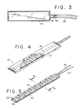
- Figure 3 is a top view of the illuminating member of one embodiment of the present invention.
- Figure 4 is perspective view with sections removed of a pressure actuated switch of one embodiment of the present invention.
- Figure 5 is a perspective view of the electrically operative elements of the switch shown in Figure 4.
- Figure 6 is an exploded view of the electrically operative elements of the switch shown in Figure 4.
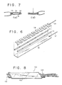
- Figures 7A and 7B are cross-sectional views taken along lines 7-7 of Figure 5.
- Figure 8 is a perspective view of another embodiment of the illuminated pressure-actuated switch of the present invention.
- the illuminated, press-at-any-point switching device 10 of the present invention comprises an outer protective envelope 50, an illuminating member 20, and a switching element 30 which is provided with an protective sleeve 31.
- each electrically operative element is protected by two moisture-proof barriers in order to provide added protection.
- a moisture-proof outer envelope 50 having a front panel 51 and a rear panel 56 are joined along their peripheral edges by heat sealing, e.g. R-F sealing, or any other conventional method.
- Outer envelope 50 may be opaque and provided with a translucent window 52 or may be formed entirely of a translucent material.
- Outer envelope 50 is advantageously provided with a reinforced conduit 54 for connecting the internal electrical components of switching 10 device with suitable electrical power sources or controls (not shown) via insulated conductors.
- the protective outer envelope may be extruded around the switching element 30 and illuminating member 20 described below.
- the outer envelope 50 may be formed of moisture-proof materials such as polyvinylchloride.
- suitable materials include impact-resistant polycarbonates such as LexanTM, a product of the General Electric Company.
- LexanTM a product of the General Electric Company.
- the illustrated press-at-any-point switch 100 is elongated and generally rectangular, the present invention is not limited to the illustrated configuration.
- the present invention can be used to provide an illuminated switching device which is square or which has an irregular shape with dimensions virtually unlimited for practical purposes.
- the illuminating member 20 of one preferred embodiment of the present invention is shown in the illustration of Figure 2 wherein the top sheet 51 of outer envelope 50 has been separated from bottom sheet 56 and partially peeled away to expose the illuminating member 20 and a press-at-any-point switch 30. While various illuminating members may be used in practicing the present invention, in the preferred illustrated embodiment, the illuminating member 20 is in the form of a flexible, luminescent lamp which receives power through electrical leads 24.
- the illuminating member 20 is preferably substantially planar and relatively incompressible such that effectively all of the pressure applied to the illuminated switching device 10 is transmitted to the switching member 30.
- Such thin, flexible lamps are commercially available.
- Figure 3 clearly shows the location of electrical contacts 24 of the illuminating member 20 illustrated in Fig. 2. Electrical contacts 24 are connected to suitable electrical conductors 26, e.g. copper wires. The points of connection may be enclosed with a suitable protective insulator 25.
- the switching element 30 of the present invention may comprise a known pressure-actuated switching arrangement.
- one preferred press-at-any-point switching element 30, which is durable while relatively inexpensive and easy to manufacture, comprises a protective sleeve 31.
- the sleeve 31 is sealed at both ends thereof to provide additional protection to the electrical elements of the switching member 30 from moisture and environmental effects.
- the illustrated switching element 30 also comprises a lower electrically-conductive contact 32 and an upper electrically conductive contact 34 which are separated by electrical insulators 33.
- the electrically conductive contacts are connected to external sources of power and/or controls via wires 37,39 respectively.
- the insulators 33 are designed to normally maintain electrical contacts 32,34 in spaced relation thereby preventing electrical communication between the two contacts.
- insulators 33 are preferably disposed between the outer edges of contacts 32,34. In this fashion, when a force is applied to upper contact 34, the upper contact is pushed into lower contact 32 as shown in Fig. 7B, thereby establishing electrical communication between the contacts.
- the electrically conductive contacts may be formed of any suitable electrically conductive material such as copper and may be formed in various configurations. It will be appreciated by those skilled in the art that the shape and dimensions of the electrical contacts may vary depending upon the particular application for which the switch is designed. For example, the deformation resistance of the upper electrical contact 34 may be decreased by removing selected portions thereof as shown in the illustrated embodiment.
- the insulators 33 may also be formed of conventional materials such as rubber, foam or plastics.
- protective sleeve 31 may advantageously be provided with a raised bead 35. It will be appreciated by those skilled in the art that the raised bead 35 helps to direct an applied pressure to the center portion of the contacts where the upper contact 34 has greatest resiliency. The cooperation of the bead 35 and relatively incompressible lamp 20 can effectively extend the actuation zone of this embodiment beyond the edges of the switching element 30.
- actuation zone is meant to indicate the portion or portions of a switching device at which the application of pressure will result in electrical communication between the contacts.
- a plurality of switching elements may be positioned adjacent to one or more lamps within one switching device.
- the positioning of the switching elements is important to insure that the application of pressure to the actuation zone of the switching device will result in an electrical communication between the contacts.
- a flexible illuminating member may be adhered directly to at least one of the contacts in the manner illustrated in Figure 8.
- the protective sleeve 31 for the switching element 30 and the outer protective envelope 50 are omitted.
- the illumination member 120 is disposed immediately adjacent to the upper electrically conductive contact of switching element 130. If desired, the illumination member 120 may be secured to the switching member 130 by an adhesive such as a cyanoacrylate or an epoxy adhesive.
- the embodiment of the present invention illustrated in Figure 8 is simpler to manufacture than the embodiment 1-7 and is particularly suited for applications wherein the additional protection of an outer envelope and a separate inner protective envelope around the electrical contacts are unnecessary.
Landscapes
- Push-Button Switches (AREA)
- Switch Cases, Indication, And Locking (AREA)
- Mechanisms For Operating Contacts (AREA)
Applications Claiming Priority (2)
| Application Number | Priority Date | Filing Date | Title |
|---|---|---|---|
| US491542 | 1990-03-12 | ||
| US07/491,542 US5118910A (en) | 1990-03-12 | 1990-03-12 | Illuminated, pressure-actuated switch |
Publications (2)
| Publication Number | Publication Date |
|---|---|
| EP0446997A2 true EP0446997A2 (fr) | 1991-09-18 |
| EP0446997A3 EP0446997A3 (en) | 1992-08-12 |
Family
ID=23952664
Family Applications (1)
| Application Number | Title | Priority Date | Filing Date |
|---|---|---|---|
| EP19910200522 Withdrawn EP0446997A3 (en) | 1990-03-12 | 1991-03-11 | Illuminated, pressure-actuated switch |
Country Status (4)
| Country | Link |
|---|---|
| US (1) | US5118910A (fr) |
| EP (1) | EP0446997A3 (fr) |
| JP (1) | JPH04220910A (fr) |
| CA (1) | CA2037402A1 (fr) |
Cited By (3)
| Publication number | Priority date | Publication date | Assignee | Title |
|---|---|---|---|---|
| GB2335310A (en) * | 1998-03-11 | 1999-09-15 | Draftex Ind Ltd | A force-responsive sensor |
| DE10014698B4 (de) * | 1999-06-25 | 2009-12-10 | Tokyo Sensor Co., Ltd. | Schalter mit durchgehender Länge und Verfahren zu dessen Herstellung |
| GB2477486A (en) * | 2009-09-24 | 2011-08-03 | Cronapress Ltd | An elongate switch for use in an alarm system |
Families Citing this family (31)
| Publication number | Priority date | Publication date | Assignee | Title |
|---|---|---|---|---|
| US5260530A (en) * | 1990-03-12 | 1993-11-09 | Tapeswitch Corporation Of America | Illuminated, pressure-actuated switch |
| US5239148A (en) * | 1991-05-15 | 1993-08-24 | Progressive Engineering Technologies Corp. | Lane discriminating traffic counting device |
| US5399819A (en) * | 1994-03-29 | 1995-03-21 | Morton International, Inc. | Airbag cover horn switch |
| US5510586A (en) * | 1995-01-11 | 1996-04-23 | Tapeswitch Corporation Of America | Switch joint for electrical switching mats |
| JPH10321070A (ja) * | 1996-07-09 | 1998-12-04 | Ebatsuku:Kk | 管状スイッチ及びその接続器具 |
| US5764153A (en) * | 1996-11-29 | 1998-06-09 | Vedaa; Richard M. | Pressure controlled alarm clock system |
| US5887856A (en) * | 1997-07-03 | 1999-03-30 | Everly, Ii; Robert J. | Illuminated fence system |
| DE69804320T2 (de) * | 1997-08-14 | 2002-11-14 | Gencorp Property Inc., Sacramento | Kraftabgängige detektoren und systemen |
| US6584678B2 (en) | 2001-04-17 | 2003-07-01 | Lester E. Burgess | Pressure actuated switching device and transfer method for making same |
| US7208694B2 (en) | 2004-04-16 | 2007-04-24 | Wabtec Holding Corp. | Capacitance activated switch device |
| US6963040B1 (en) * | 2004-12-06 | 2005-11-08 | Westinghouse Air Brake Technologies Corporation | Illuminated touch switch |
| US20060279133A1 (en) * | 2005-06-10 | 2006-12-14 | River City Manufacturing Inc. | Retaining system for securing a cutting tool to a support block |
| US7458699B2 (en) * | 2006-03-03 | 2008-12-02 | Rawlings Sporting Goods Company, Inc. | Ball glove having impact detection and visible annunciation |
| EP2013955A4 (fr) * | 2006-04-21 | 2010-10-13 | Wabtec Holding Corp | Adaptateur à deux fils |
| USD566658S1 (en) | 2006-06-19 | 2008-04-15 | Lutron Electronics Co., Inc. | Dual dimmer switch |
| USD563901S1 (en) * | 2006-06-19 | 2008-03-11 | Lutron Electronics Co., Inc. | Dimmer switch |
| US7791595B2 (en) * | 2006-06-20 | 2010-09-07 | Lutron Electronics Co., Inc. | Touch screen assembly for a lighting control |
| US20100013649A1 (en) * | 2006-06-20 | 2010-01-21 | Spira Joel S | Load control device having audible feedback |
| US7566995B2 (en) * | 2006-06-20 | 2009-07-28 | Lutron Electronics Co., Inc. | Touch screen having a uniform actuation force and a maximum active area |
| US7608948B2 (en) * | 2006-06-20 | 2009-10-27 | Lutron Electronics Co., Inc. | Touch screen with sensory feedback |
| US7855543B2 (en) * | 2006-06-20 | 2010-12-21 | Lutron Electronics Co., Inc. | Force invariant touch sensitive actuator |
| USD572202S1 (en) * | 2006-07-17 | 2008-07-01 | Lutron Electronics Co., Inc. | Dimmer switch |
| US20100231400A1 (en) * | 2007-10-09 | 2010-09-16 | Meo Mio, Llc | Lighting activation systems and methods |
| USD624882S1 (en) | 2009-03-17 | 2010-10-05 | Lutron Electronics Co., Inc. | Lighting control keypad |
| USD624881S1 (en) | 2009-03-17 | 2010-10-05 | Lutron Electronics Co., Inc. | Lighting control keypad |
| US20100242337A1 (en) * | 2009-03-30 | 2010-09-30 | Steve Cummings | Ice fishing device |
| JP5766626B2 (ja) * | 2012-01-27 | 2015-08-19 | サンコール株式会社 | 感圧スイッチ |
| US8985274B2 (en) | 2012-08-13 | 2015-03-24 | Sam Carbis Asset Management, Llc | Flatbed loading system with self-aligning platforms |
| USD751044S1 (en) * | 2014-05-22 | 2016-03-08 | Hzo, Inc. | Control switch for an electronic device |
| JP1638140S (fr) * | 2018-04-04 | 2019-08-05 | ||
| USD1078663S1 (en) * | 2023-01-13 | 2025-06-10 | Banner Engineering Corp. | Touch sensor electric switch |
Family Cites Families (9)
| Publication number | Priority date | Publication date | Assignee | Title |
|---|---|---|---|---|
| CA1102767A (fr) * | 1978-03-15 | 1981-06-09 | Decca Limited | Panneaux luminescents |
| US4258096A (en) * | 1978-11-09 | 1981-03-24 | Sheldahl, Inc. | Composite top membrane for flat panel switch arrays |
| US4293752A (en) * | 1980-01-11 | 1981-10-06 | Tapeswitch Corporation Of America | Self adhering tape switch |
| US4425601A (en) * | 1981-08-31 | 1984-01-10 | Robert Donahue | Stairway lighting system |
| US4551713A (en) * | 1983-01-28 | 1985-11-05 | Aossey Joseph W | Pet door mat alarm |
| US4532395A (en) * | 1983-09-20 | 1985-07-30 | Timex Corporation | Electroluminescent flexible touch switch panel |
| US4551595A (en) * | 1984-07-16 | 1985-11-05 | Tapeswitch Corporation Of America | Tape switch with corrugated wavy conductor |
| SE445504B (sv) * | 1984-11-13 | 1986-06-23 | Tocksfors Verkstads Ab | Reletungenhet |
| US4947298A (en) * | 1989-08-21 | 1990-08-07 | Stephen John L | Bed lighting apparatus |
-
1990
- 1990-03-12 US US07/491,542 patent/US5118910A/en not_active Expired - Lifetime
-
1991
- 1991-03-01 CA CA002037402A patent/CA2037402A1/fr not_active Abandoned
- 1991-03-11 EP EP19910200522 patent/EP0446997A3/en not_active Withdrawn
- 1991-03-12 JP JP3046704A patent/JPH04220910A/ja active Pending
Cited By (6)
| Publication number | Priority date | Publication date | Assignee | Title |
|---|---|---|---|---|
| GB2335310A (en) * | 1998-03-11 | 1999-09-15 | Draftex Ind Ltd | A force-responsive sensor |
| GB2335310B (en) * | 1998-03-11 | 2001-09-19 | Draftex Ind Ltd | Force-responsive detectors and systems |
| US6571511B1 (en) | 1998-03-11 | 2003-06-03 | Draftex Industries Limited | Force-responsive detectors and systems and methods of making them |
| DE10014698B4 (de) * | 1999-06-25 | 2009-12-10 | Tokyo Sensor Co., Ltd. | Schalter mit durchgehender Länge und Verfahren zu dessen Herstellung |
| GB2477486A (en) * | 2009-09-24 | 2011-08-03 | Cronapress Ltd | An elongate switch for use in an alarm system |
| GB2477486B (en) * | 2009-09-24 | 2011-11-23 | Cronapress Ltd | An elongate switch for use in an alarm system |
Also Published As
| Publication number | Publication date |
|---|---|
| US5118910A (en) | 1992-06-02 |
| CA2037402A1 (fr) | 1991-09-13 |
| EP0446997A3 (en) | 1992-08-12 |
| JPH04220910A (ja) | 1992-08-11 |
Similar Documents
| Publication | Publication Date | Title |
|---|---|---|
| US5118910A (en) | Illuminated, pressure-actuated switch | |
| US4954673A (en) | Highly sensitive switch for actuation of a device upon force being applied thereto | |
| HU9302684D0 (en) | Protecting equipment for sash-windows against pinch | |
| AU626380B2 (en) | Gas-blast electrical circuit breaker | |
| AU6954187A (en) | Current breaking device with solid-state switch and built-in protective circuit breaker | |
| GB9424912D0 (en) | Electric switch device with separable contacts | |
| US5260530A (en) | Illuminated, pressure-actuated switch | |
| EP0102703A2 (fr) | Interrupteur bipolaire à membrane présentant une séquence de fermeture préférée | |
| ES2130242T3 (es) | Cable electrico. | |
| DE69418427D1 (de) | Elektrisch leitfähige Silikonkautschukzusammensetzung | |
| AU3592384A (en) | Molded case circuit breaker with movable lower electrical contact | |
| BR9611005A (pt) | Comutador com folha condutora flexível que age como contato estacionário e conexão a contatos conectores | |
| DE69402580D1 (de) | Gekapselte elektrische Leiteranordnung | |
| KR890015324A (ko) | 시각 브레이크 스위치 | |
| CA2034148A1 (fr) | Pressostat normalement ferme | |
| SE8404585D0 (sv) | Schalterleiste an einem armaturenbrett fur fahrzeuge, insbesondere kraftfahrzeuge | |
| EP1109140A3 (fr) | Elément de vitre | |
| DE59410154D1 (de) | Elektrisch leitfähige Formkörper | |
| EP0435044A3 (en) | Half-product with electrically conductive plastic layers | |
| EP0199593A3 (fr) | Contacts d'interrupteur pour courant fort | |
| DE3278179D1 (en) | Sealed electrical contact assembly and electrical switch made therefrom | |
| NO20013134D0 (no) | Elektrisk bryter | |
| SE8501516L (sv) | Membranomkopplare | |
| GB2088637A (en) | Electric Switches | |
| AU6966191A (en) | Electrical conductors of conductive resin |
Legal Events
| Date | Code | Title | Description |
|---|---|---|---|
| PUAI | Public reference made under article 153(3) epc to a published international application that has entered the european phase |
Free format text: ORIGINAL CODE: 0009012 |
|
| AK | Designated contracting states |
Kind code of ref document: A2 Designated state(s): AT BE CH DE DK ES FR GB IT LI LU SE |
|
| PUAL | Search report despatched |
Free format text: ORIGINAL CODE: 0009013 |
|
| AK | Designated contracting states |
Kind code of ref document: A3 Designated state(s): AT BE CH DE DK ES FR GB IT LI LU SE |
|
| 17P | Request for examination filed |
Effective date: 19930119 |
|
| 17Q | First examination report despatched |
Effective date: 19940214 |
|
| STAA | Information on the status of an ep patent application or granted ep patent |
Free format text: STATUS: THE APPLICATION IS DEEMED TO BE WITHDRAWN |
|
| 18D | Application deemed to be withdrawn |
Effective date: 19940825 |