EP0447466B1 - Optisches aufzeichnungs- und/oder wiedergabe-gerät - Google Patents
Optisches aufzeichnungs- und/oder wiedergabe-gerät Download PDFInfo
- Publication number
- EP0447466B1 EP0447466B1 EP90900792A EP90900792A EP0447466B1 EP 0447466 B1 EP0447466 B1 EP 0447466B1 EP 90900792 A EP90900792 A EP 90900792A EP 90900792 A EP90900792 A EP 90900792A EP 0447466 B1 EP0447466 B1 EP 0447466B1
- Authority
- EP
- European Patent Office
- Prior art keywords
- lens
- optical recording
- accordance
- recording
- reproduction apparatus
- Prior art date
- Legal status (The legal status is an assumption and is not a legal conclusion. Google has not performed a legal analysis and makes no representation as to the accuracy of the status listed.)
- Expired - Lifetime
Links
- 230000003287 optical effect Effects 0.000 title claims abstract description 33
- 239000000428 dust Substances 0.000 claims abstract description 17
- 238000004140 cleaning Methods 0.000 claims abstract description 14
- 239000011248 coating agent Substances 0.000 claims abstract 2
- 238000000576 coating method Methods 0.000 claims abstract 2
- 238000000034 method Methods 0.000 claims description 3
- 239000012530 fluid Substances 0.000 claims 2
- 239000012072 active phase Substances 0.000 claims 1
- 238000004146 energy storage Methods 0.000 claims 1
- 230000008021 deposition Effects 0.000 abstract description 2
- 238000007664 blowing Methods 0.000 description 2
- 239000002245 particle Substances 0.000 description 2
- 101100252507 Triticum aestivum ELAC gene Proteins 0.000 description 1
- 238000009825 accumulation Methods 0.000 description 1
- 230000001680 brushing effect Effects 0.000 description 1
- 230000000694 effects Effects 0.000 description 1
- 238000012044 lysine affinity chromatography Methods 0.000 description 1
- 230000001681 protective effect Effects 0.000 description 1
Images

Classifications
-
- G—PHYSICS
- G11—INFORMATION STORAGE
- G11B—INFORMATION STORAGE BASED ON RELATIVE MOVEMENT BETWEEN RECORD CARRIER AND TRANSDUCER
- G11B7/00—Recording or reproducing by optical means, e.g. recording using a thermal beam of optical radiation by modifying optical properties or the physical structure, reproducing using an optical beam at lower power by sensing optical properties; Record carriers therefor
- G11B7/08—Disposition or mounting of heads or light sources relatively to record carriers
-
- G—PHYSICS
- G11—INFORMATION STORAGE
- G11B—INFORMATION STORAGE BASED ON RELATIVE MOVEMENT BETWEEN RECORD CARRIER AND TRANSDUCER
- G11B7/00—Recording or reproducing by optical means, e.g. recording using a thermal beam of optical radiation by modifying optical properties or the physical structure, reproducing using an optical beam at lower power by sensing optical properties; Record carriers therefor
-
- G—PHYSICS
- G11—INFORMATION STORAGE
- G11B—INFORMATION STORAGE BASED ON RELATIVE MOVEMENT BETWEEN RECORD CARRIER AND TRANSDUCER
- G11B7/00—Recording or reproducing by optical means, e.g. recording using a thermal beam of optical radiation by modifying optical properties or the physical structure, reproducing using an optical beam at lower power by sensing optical properties; Record carriers therefor
- G11B7/12—Heads, e.g. forming of the optical beam spot or modulation of the optical beam
- G11B7/121—Protecting the head, e.g. against dust or impact with the record carrier
Definitions
- the invention relates to an optical recording and / or reproducing device with a recording and / or scanning device which is equipped with a lens, means or measures being provided which keep the lens surface largely dust-free and the information carrier, a rotating disk , lies on a turntable which is driven by a motor.
- a device for blowing away and / or aspirating small particles in the process of taking up plates by the TED method from AEG-Telefunken has also become known.
- JP-A-63 255839 an optical recording and reproducing device is known which is equipped with a scanning device, a lens and a device which covers the lens in a dust-protecting manner in the end position of the scanning device.
- JP-A-61 224151 describes an optical recording and reproducing device whose scanning device is protected from dust in the rest position under a protective hood.
- the objective lens of the optical scanning device is moved from the reading area under a brush-shaped cleaning device. Under the cleaning device, the objective lens is reciprocated to brush dust off its surface. After cleaning, the objective lens remains in the rest position under the brush-shaped cleaning device so that it is protected from dust.
- JP-A-59 065954 discloses a reproducing device which capacitively scans a disk by means of an electrode.
- the surface of the electrode is cleaned by a rotating brush.
- the arm on which the electrode sits is vibrating to enhance the cleaning effect.
- a brush sits on the surface of a cleaning plate, brushing the dust off the objective lens.
- JP-A-63 273226 there is also known an optical recording and reproducing device with an objective lens, an optical scanning device and a cleaning plate.
- the object on which the invention is based is to reduce or remove disruptive dust particle deposits on the lens surface of the optical system.
- the deposition of dust on the lens surface of the optical recording and / or scanning device can be reduced or prevented by suitable means.
- FIG. 1 shows a mechanical device which is actuated by the recording and / or scanning device 3 when it is moved into its rest or end position near the platter 2.
- the recording and / or scanning device 3 is also shown in a position within its working range, the lens 4 being released in that the rotatable cover 5 pivots counterclockwise under the action of the tension spring 8 up to the stop 7 of an arm 9 of the cover 5 .
- the cover 5 pivots clockwise to the drawn position, the cover 5 covering the lens 4 and thus protecting it from dust.
- This rotation is brought about against the force of the tension spring 8 as soon as the recording and / or scanning device 3 pushes a second arm 10 of the cover 5 against a stop 6 fastened to the chassis or the base plate 1.
- the part having the arms 9 and 10 is rigidly connected to the cover 5 and rotatable about the axis 11. The illustration is drawn about 2 times larger than reality.
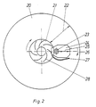
- FIG. 2 shows an approximately natural size device with which a directed air flow is generated over the lens surface.
- a CD disk 20 is to be thought of as transparent, as is the turntable 21 underneath, which has curved ribs 28 on its underside.
- arrow 26 these generate an air flow directed through the deflection part 27 over the surface of the lens 23 on the upper side of the recording and / or scanning device 24.
- the arrows 25, which are directed in the opposite direction, are intended to indicate the radial direction of movement of the recording and / or scanning device 24 during game operation.
- the radially directed double arrow 22 is intended to identify the probing area.
Landscapes
- Physics & Mathematics (AREA)
- Optics & Photonics (AREA)
- Optical Head (AREA)
- Overhead Projectors And Projection Screens (AREA)
- Non-Portable Lighting Devices Or Systems Thereof (AREA)
Abstract
Description
- Die Erfindung betrifft ein optisches Aufzeichnungs- und/oder Wiedergabe-Gerät mit einer Aufzeichnungs- und/oder Abtastvorrichtung, die mit einer Linse ausgerüstet ist, wobei Mittel oder Maßnahmen vorgesehen sind, welche die Linsenoberfläche weitgehend staubfrei halten und wobei der Informationsträger, eine rotierende Scheibe, auf einem Plattenteller liegt, der von einem Motor angetrieben wird.
- Es hat sich beim Betrieb derartiger Geräte, insbesondere bei CD-Spielern, gezeigt, daß abgelagerter Staub auf Linsenoberflächen von Abtastsystemen zu einer erheblichen Verringerung der Abtastqualität führen kann. Das äußert sich z.B. in einer schlechten Musikwiedergabe.
- Auch bei Plattenspielern für Analog-Schallplatten mit mechanischer Abtastung einer Tonspur mittels einer Abtastspitze verschlechtert Staubansammlung an dieser die Wiedergabe. Bei einem Abtastsystem der Fa. Shure Brothers, Typ VR15, wurde deshalb ein kleines Bürstchen derart am Abtastsystem angeordnet, daß es dem Abtaster voraus eine Anzahl benachbarter Rillen von Staub frei fegte.
- Bekannt wurde auch eine Lösung, bei welcher der Abtaster auf seinem Weg von und/oder zu der Tonarmablage eine kleine Bürste passierte, wobei Staub von der Abtasterspitze abgestreift wurde. Hersteller war die Fa. ELAC, Kiel.
- Eine Vorrichtung zum Wegblasen und/oder Absaugen kleine Partikel bei dem Aufnahmevorgang von Platten nach dem TED-Verfahren von AEG-Telefunken wurde ebenfalls bekannt.
- Aus der JP-A-63 255839 ist ein optisches Aufzeichnungs- und Wiedergabegerät bekannt, das mit mit einer Abtastvorrichtung, einer Linse und einer in der Endposition der Abtastvorrichtung die Linse staubschützend abdeckenden Vorrichtung ausgestattet ist.
- In der JP-A-61 224151 ist ein optisches Aufzeichnungs- und Wiedergabegerät beschrieben, dessen Abtastvorrichtung in Ruhestellung unter einer Schutzhaube vor Staub geschützt ist.
- Aus der JP-A-61 280043 ist ein optisches Aufzeichnungs- und Wiedergabegerät mit einer Objektivlinse und einer optischen Abtastvorrichtung bekannt.
- Zur Reinigung wird die Objektivlinse der optischen Abtastvorrichtung aus dem Lesebereich unter eine bürstenförmige Reinigungsvorrichtung gefahren. Unter der Reinigungsvorrichtung wird die Objektivlinse hin- und herbewegt, um Staub von ihrer Oberfläche zu bürsten. Nach Ende der Reinigung bleibt die Objektivlinse in der Ruhestellung unter der bürstenförmigen Reinigungsvorrichtung, damit sie vor Staub geschützt ist.
- Aus der JP-A-59 065954 ist ein mittels einer Elektrode kapazitiv eine Platte abtastendes Wiedergabegerät bekannt.
- Die Oberfläche der Elektrode wird von einer rotierenden Bürste gereinigt. Zusätzlich vibriert der Arm, auf dem die Elektrode sitzt, um die Reinigungswirkung zu verstärken.
- Aus der JP-A-63 136371 ist ein optisches Aufzeichnungs- und Wiedergabegerät mit einer Objektivlinse und einer optischen Abtastvorrichtung bekannt.
- Auf der Oberfläche einer Reinigungsplatte sitzt eine Bürste, die den Staub von der Objektivlinse bürstet.
- Aus der JP-A-63 273226 ist ebenfalls ein optisches Aufzeichnungs- und Wiedergabegerät mit einer Objektivlinse, einer optischen Abtastvorrichtung und einer Reinigungsplatte bekannt.
- Störende Staubteilchenablagerungen auf der Linsenoberfläche des optischen Systems zu reduzieren bzw. zu entfernen, ist die der Erfindung zugrunde liegende Aufgabe.
- Diese Aufgabe wird erfindungsgemäß nach Anspruch 1 gelöst. Weitere Einzelheiten und Ausgestaltungen der Erfindung sind den übrigen Ansprüchen zu entnehmen.
- Nach der Erfindung kann mit geeigneten Mitteln die Ablagerung von Staub auf der Linsenoberfläche der optische Aufzeichnungs- und/oder Abtastvorrichtung vermindert bzw. verhindert werden.
- An Hand der Zeichnung werden nachfolgend zwei Ausführungsbeispiele der Erfindung erläutert. Diese zeigt in
- Figur 1
- in stark vereinfachter Darstellung eine von der Aufzeichnungs- und/oder Abtastvorrichtung betätigte mechanische Linsenabdeckung in Draufsicht;
- Figur 2
- das Prinzip einer Blasvorrichtung in Draufsicht, wobei ein Luftstrom über die Linsenoberfläche gerichtet ist.
- Figur 1 zeigt eine mechanische Vorrichtung, die von der Aufzeichnungs- und/oder Abtastvorrichtung 3 betätigt wird, wenn diese in ihre Ruhe- oder Endposition nahe dem Platterteller 2 bewegt wird. Die Aufzeichnungs- und/oder Abtastvorrichtung 3 ist außerdem in einer Position innerhalb ihres Arbeitsbereiches eingezeichnet, wobei die Linse 4 freigegeben ist, indem die drehbewegliche Abdeckung 5 unter der Wirkung der Zugfeder 8 entgegen dem Uhrzeigerdrehsinn bis zum Anschlag 7 eines Armes 9 der Abdeckung 5 schwenkt. Wenn die Aufzeichnungs- und/oder Abtastvorrichtung 3 durch ihren Radial-Antrieb in die Ruheposition bewegt wird, schwenkt die Abdeckung 5 im Uhrzeigerdrehsinn bis zur gezeichneten Position, wobei die Abdeckung 5 die Linse 4 überdeckt und so vor Staub schützt. Diese Drehung wird gegen die Kraft der Zugfeder 8 bewirkt, sobald die Aufzeichnungs- und/oder Abtastvorrichtung 3 einen zweiten Arm 10 der Abdeckung 5 gegen einen am Chassis bzw. der Grundplatte 1 befestigten Anschlag 6 stößt. Das die Arme 9 und 10 aufweisende Teil ist mit der Abdeckung 5 starr verbunden und um die Achse 11 drehbar. Die Darstellung ist gebenüber der Wirklichkeit etwa 2-fach vergrößert gezeichnet.
- In etwa natürlicher Größe ist in Figur 2 eine Vorrichtung gezeigt, mit der ein gerichteter Luftstrom über die Linsenoberfläche erzeugt wird. In der Darstellung ist eine CD-Platte 20 durchsichtig zu denken, ebenso der darunter befindliche Plattenteller 21, der auf seiner Unterseite gekrümmte Rippen 28 aufweist. Diese erzeugen bei der schnellen Drehung des Plattentellers 21 in der angedeuteten Drehrichtung, Pfeil 26, einen Luftstrom, gerichtet durch das Ablenkteil 27 über die Oberfläche der Linse 23 auf der Obereite der Aufzeichnungs- und/oder Abtastvorrichtung 24. Die entgegengesetzt gerichteten Pfeile 25 sollen die radiale Bewegungsrichtung der Aufzeichnungs- und/oder Abtastvorrichtung 24 während des Spielbetriebs andeuten. Der radial gerichtete Doppelpfeil 22 soll den Antastbereich kennzeichnen.
Claims (16)
- Optisches Aufzeichnungs- und/oder Wiedergabe-Gerät mit einer Aufzeichnungs- und/oder Abtastvorrichtung, die mit einer Linse ausgerüstet ist, wobei Mittel oder Maßnahmen vorgesehen sind, welche die Linsenoberfläche weitgehend staubfrei halten und wobei der Informationsträger, eine rotierende Scheibe (20), auf einem Plattenteller (21) liegt, der von einem Motor angetrieben wird, dadurch gekennzeichnet, daß die eine Seite des Plattentellers (21), die nicht zur Auflage der Scheibe (20) dient, mit Rippen (28) versehen ist, so daß ein Luftstrom erzeugt wird, der von Leitmitteln (27) über die Linsenoberfläche gelenkt wird.
- Optisches Aufzeichnungs- und/oder Wiedergabe-Gerät nach Anspruch 1, dadurch gekennzeichnet, daß eine mechanische Vorrichtung, die von der Aufzeichnungs- und/oder Abtastvorrichtung (3) betätigt wird, wenn diese in ihre Ruhe- oder Endposition oder Bereitschaftsstellung gelangt, so ausgebildet ist, daß sie die Linse (4) in dieser Position staubschützend abdeckt.
- Optisches Aufzeichnungs- und/oder Wiedergabe-Gerät nach Anspruch 2, dadurch gekennzeichnet, daß die mechanische Vorrichtung aus einem mehrarmigen Hebel besteht, dessen einer Arm (10) einen Anschlag (6) für die Aktivierung durch die optische Aufzeichnungs- und/oder Abtastvorrichtung (3) besitzt, und dessen anderer Arm (9) eine Abdeckung (5) für die Linse (4) aufweist, daß an dem Hebel ein Rückstellmittel (8) dafür sorgt, daß der Hebel beim Start des Gerätes die optische Aufzeichnungs- und/oder Abtastvorrichtung (3) aus der Ruheposition freigibt.
- Optisches Aufzeichnungs- und/oder Wiedergabe-Gerät nach Anspruch 1, dadurch gekennzeichnet, daß eine ortsfeste Linsenabdeckung so angebracht ist, daß die Aufzeichnungs- und/oder Abtastvorrichtung bei Abschalten des Gerätes, ebenso wie bei Pause, in Bereitschaftsstellung und/oder bei der Wiederholung von Abtastvorgängen in eine solche Ruheposition oder Bereitschaftsstellung gesteuert wird, daß die Linsenabdeckung (5) die Linse (4) abdeckt.
- Optisches Aufzeichnungs- und/oder Wiedergabe-Gerät nach Anspruch 4, dadurch gekennzeichnet, daß die Linsenabdeckung (5) auf ihrer der Linse (4) zugewandten Seite mit einer zur Entfernung von Staub geeigneten Auflage oder Beschichtung versehen ist.
- Optisches Aufzeichnungs- und/oder Wiedergabe-Gerät nach Anspruch 1, 2, 3, 4 oder 5, dadurch gekennzeichnet, daß die Linsenabdeckung (5) über eine Zuführungs-Einrichtung mit einer Reinigungsflüssigkeit getränkt werden kann.
- Optisches Aufzeichnungs- und/oder Wiedergabe-Gerät nach Anspruch 6, dadurch gekennzeichnet, daß an der Geräteaußenseite eine verschließbare öffnung zum Nachfüllen der Reinigungsflüssigkeit vorgesehen ist.
- Optisches Aufzeichnungs- und/oder Wiedergabe-Gerät nach Anspruch 1, 2, 3, 4, 5, 6 oder 7, dadurch gekennzeichnet, daß die Linse (4) der Aufzeichnungs- und/oder Wiedergabevorrichtung gerüttelt wird.
- Optisches Aufzeichnungs- und/oder Wiedergabe-Gerät mit einem Fokus- und/oder Spurregelkreis nach Anspruch 8, dadurch gekennzeichnet, daß der Grob- und/oder Feinantrieb des Spurregelkreises die Linse (4) rüttelt.
- Optisches Aufzeichnungs- und/oder Wiedergabe-Gerät nach Anspruch 8 oder 9, dadurch gekennzeichnet, daß das Stellglied des Fokusregelkreises die Linse (4) rüttelt.
- Optisches Aufzeichnungs- und/oder Wiedergabe-Gerät nach Anspruch 9 und 10, dadurch gekennzeichnet, daß die Rüttelfrequenz in radialer Richtung van der in Fokus-Richtung abweicht.
- Optisches Aufzeichnungs- und/oder Wiedergabe-Gerät nach Anspruch 11, dadurch gekennzeichnet, daß die Rüttelfrequenz in radialer Richtung höher gewählt ist als in Fokus-Richtung.
- Optisches Aufzeichnungs- und/oder Wiedergabe-Gerät nach Anspruch 4 oder 5, dadurch gekennzeichnet, daß die Linsenabdeckung bzw. ihre Auflage zwecks Erneuerung auswechselbar konstruiert ist.
- Optisches Aufzeichnungs- und/oder Wiedergabe-Gerät nach einem oder mehreren der voranstehenden Ansprüche, dadurch gekennzeichnet, daß durch Steuerung der Aufzeichnungs- und/oder Abtastvorrichtung sicher gestellt wird, daß die Reinigung der Linse (4) auch bei Bedienerbefehlen wie Abschalten, Bereitschaft, Wiederholung und Pause vor und/oder nach Aktivierungsphasen der Aufzeichnungs- und/oder Abtastvorrichtung (3) durchgeführt werden.
- Optisches Aufzeichnungs- und/oder Wiedergabe-Gerät nach einer oder mehreren der voranstehenden Ansprüche, dadurch gekennzeichnet, daß für den Fall eines versehentlichen Ziehens des Netzsteckers oder bei Netzausfall ein Energiespeicher die für die Steuerung der Reinigung notwendige Energie liefert.
- Optisches Aufzeichnungs- und/oder Wiedergabe-Gerät nach einem oder mehreren der voranstehenden Ansprüche, dadurch gekennzeichnet, daß ein Zeitglied beim Ausschalten des Gerätes sicher stellt, daß die Aufzeichnungs- und/oder Abtastvorrichtung (3) in die Ruhe- und Reinigungsposition gelangt, bevor die Netzspannungsabschaltung wirksam wird.
Priority Applications (1)
| Application Number | Priority Date | Filing Date | Title |
|---|---|---|---|
| AT90900792T ATE103407T1 (de) | 1988-11-30 | 1990-06-21 | Optisches aufzeichnungs- und/oder wiedergabeger|t. |
Applications Claiming Priority (2)
| Application Number | Priority Date | Filing Date | Title |
|---|---|---|---|
| DE3840311 | 1988-11-30 | ||
| DE3840311A DE3840311A1 (de) | 1988-11-30 | 1988-11-30 | Optisches aufzeichnungs- und/oder wiedergabe-geraet |
Publications (2)
| Publication Number | Publication Date |
|---|---|
| EP0447466A1 EP0447466A1 (de) | 1991-09-25 |
| EP0447466B1 true EP0447466B1 (de) | 1994-03-23 |
Family
ID=6368146
Family Applications (1)
| Application Number | Title | Priority Date | Filing Date |
|---|---|---|---|
| EP90900792A Expired - Lifetime EP0447466B1 (de) | 1988-11-30 | 1989-11-21 | Optisches aufzeichnungs- und/oder wiedergabe-gerät |
Country Status (9)
| Country | Link |
|---|---|
| US (1) | US5245601A (de) |
| EP (1) | EP0447466B1 (de) |
| JP (1) | JPH04502080A (de) |
| KR (1) | KR0181730B1 (de) |
| DE (2) | DE3840311A1 (de) |
| ES (1) | ES2051509T3 (de) |
| HK (1) | HK9796A (de) |
| HU (1) | HUT57936A (de) |
| WO (1) | WO1990006576A1 (de) |
Families Citing this family (19)
| Publication number | Priority date | Publication date | Assignee | Title |
|---|---|---|---|---|
| US5255256A (en) * | 1992-01-07 | 1993-10-19 | International Business Machines Corporation | Optical data storage system with reduced particle contamination |
| JP3320906B2 (ja) * | 1994-06-30 | 2002-09-03 | アルパイン株式会社 | ディスク装置 |
| US5465828A (en) * | 1994-07-20 | 1995-11-14 | Thomas Air Systems, Inc. | Automated mail processing cleaning system |
| US5551175A (en) * | 1994-10-17 | 1996-09-03 | Neyman; Joseph H. | Removing lint from flatwork ironer temperature sensors |
| BE1010187A3 (fr) * | 1996-05-15 | 1998-02-03 | Staar Sa | Dispositif de protection pour moyens de lecture et/ou d'enregistrement. |
| US5995467A (en) * | 1996-07-25 | 1999-11-30 | Sony Corporation | Disc recording and/or reproducing apparatus with a liftable optical pickup apparatus and coordinated lens shutter |
| JPH10199005A (ja) * | 1996-12-26 | 1998-07-31 | Sony Corp | 光学ピックアップ装置 |
| JP3352416B2 (ja) * | 1998-07-08 | 2002-12-03 | 三星電機株式会社 | 光ディスクプレーヤー |
| KR100327317B1 (ko) * | 1998-07-08 | 2002-03-06 | 이형도 | 광 디스크 플레이어 |
| US6151283A (en) * | 1998-11-19 | 2000-11-21 | Kobayashi; Asao | Lens cleaner for a disc unit |
| US6487158B2 (en) | 1999-07-14 | 2002-11-26 | Hewlett-Packard Company | Cover member and method for an optical disc drive |
| US6385161B1 (en) * | 1999-07-14 | 2002-05-07 | Hewlett-Packard Company | Securing mechanism and method for an optical disc drive |
| EP1211677A1 (de) * | 2000-12-04 | 2002-06-05 | Thomson Licensing S.A. | Plattenspieler mit integriertem Linsenreiniger und Methode zur Reinigung einer Linse |
| DE10063940A1 (de) * | 2000-12-20 | 2002-07-04 | Thomson Brandt Gmbh | Aufzeichnungs- und/oder Wiedergabegerät für optische Aufzeichnungsträger |
| US6641301B2 (en) * | 2001-04-09 | 2003-11-04 | Exergen Corporation | Radiation detector with passive air purge and reduced noise |
| US7227717B1 (en) * | 2001-06-18 | 2007-06-05 | Seagate Technology Llc | Asymmetric disk surface properties in one head disk drives |
| JP2005327350A (ja) | 2004-05-12 | 2005-11-24 | Sony Corp | 光ディスク装置の対物レンズのクリーニング方法と装置 |
| RU2334280C1 (ru) * | 2007-04-02 | 2008-09-20 | Дмитрий Анатольевич Беляев | Устройство для очистки ложемента шпинделя устройства считывания и/или записи информации на компакт-диски |
| WO2014073129A1 (ja) * | 2012-11-06 | 2014-05-15 | パナソニック株式会社 | 光ディスク装置、シート部材及び対物レンズの清浄方法 |
Family Cites Families (15)
| Publication number | Priority date | Publication date | Assignee | Title |
|---|---|---|---|---|
| GB2024495B (en) * | 1978-05-16 | 1982-12-22 | Burroughs Corp | Record-disc cover having air filtration section |
| NL8004379A (nl) * | 1980-07-31 | 1982-03-01 | Philips Nv | Inrichting voor het met behulp van een stralingsbundel inschrijven en/of uitlezen van informatie op een roterende informatieschijf. |
| JPS5965954A (ja) * | 1982-10-06 | 1984-04-14 | Victor Co Of Japan Ltd | 静電容量変化検出型再生装置における針先清掃装置 |
| JPS59154626A (ja) * | 1983-02-23 | 1984-09-03 | Canon Inc | 記録又は再生ヘツドの清掃装置 |
| JPS60127540A (ja) * | 1983-12-13 | 1985-07-08 | Matsushita Electric Ind Co Ltd | 光学式デイスクプレ−ヤの読出装置における対物レンズクリ−ナ− |
| JPS61224151A (ja) * | 1985-03-29 | 1986-10-04 | Canon Inc | 情報記録再生装置 |
| JPS61224190A (ja) * | 1985-03-29 | 1986-10-04 | Canon Inc | 情報記録再生装置 |
| JPS61280043A (ja) * | 1985-06-05 | 1986-12-10 | Nec Eng Ltd | 光デイスク装置 |
| JPS6224448A (ja) * | 1985-07-25 | 1987-02-02 | Sony Corp | 光学ピツクアツプの対物レンズクリ−ニング方法 |
| JPS6252785A (ja) * | 1985-08-30 | 1987-03-07 | Nec Corp | 光学式記録再生装置 |
| JPS63217584A (ja) * | 1987-03-04 | 1988-09-09 | Nec Corp | 光デイスクカ−トリツジ |
| JPS63255839A (ja) * | 1987-04-13 | 1988-10-24 | Matsushita Graphic Commun Syst Inc | 光デイスク記録再生装置 |
| JPS63273226A (ja) * | 1987-04-30 | 1988-11-10 | Toshiba Corp | 光学素子の清掃部材 |
| JPS6413235A (en) * | 1987-07-07 | 1989-01-18 | Matsushita Electric Industrial Co Ltd | Optical recording and reproducing device |
| JPS6462240A (en) * | 1987-09-02 | 1989-03-08 | Nippon Steel Corp | Production of rough billet by forging |
-
1988
- 1988-11-30 DE DE3840311A patent/DE3840311A1/de not_active Withdrawn
-
1989
- 1989-11-21 WO PCT/EP1989/001413 patent/WO1990006576A1/de not_active Ceased
- 1989-11-21 ES ES90900792T patent/ES2051509T3/es not_active Expired - Lifetime
- 1989-11-21 US US07/688,500 patent/US5245601A/en not_active Expired - Lifetime
- 1989-11-21 JP JP2501001A patent/JPH04502080A/ja active Pending
- 1989-11-21 KR KR1019900701642A patent/KR0181730B1/ko not_active Expired - Fee Related
- 1989-11-21 DE DE90900792T patent/DE58907308D1/de not_active Expired - Fee Related
- 1989-11-21 HU HU90401A patent/HUT57936A/hu unknown
- 1989-11-21 EP EP90900792A patent/EP0447466B1/de not_active Expired - Lifetime
-
1996
- 1996-01-18 HK HK9796A patent/HK9796A/xx not_active IP Right Cessation
Non-Patent Citations (1)
| Title |
|---|
| Patent Abstracts of Japan, Band 8, Nr. 171, (P-293)(1608), 8. August 1984;& JP-A-5965954 * |
Also Published As
| Publication number | Publication date |
|---|---|
| HK9796A (en) | 1996-01-26 |
| WO1990006576A1 (de) | 1990-06-14 |
| US5245601A (en) | 1993-09-14 |
| KR900702515A (ko) | 1990-12-07 |
| KR0181730B1 (ko) | 1999-10-01 |
| DE3840311A1 (de) | 1990-05-31 |
| ES2051509T3 (es) | 1994-06-16 |
| HU900401D0 (en) | 1991-08-28 |
| EP0447466A1 (de) | 1991-09-25 |
| DE58907308D1 (de) | 1994-04-28 |
| JPH04502080A (ja) | 1992-04-09 |
| HUT57936A (en) | 1991-12-30 |
Similar Documents
| Publication | Publication Date | Title |
|---|---|---|
| EP0447466B1 (de) | Optisches aufzeichnungs- und/oder wiedergabe-gerät | |
| US6084753A (en) | Method and apparatus for removing debris from a slider in a disk drive using load/unload technology | |
| EP0360144A2 (de) | Optische Speichervorrichtung und optisches Informationsverarbeitungsgerät | |
| EP0770994A2 (de) | Platte zum Reinigen einer Linse | |
| DE4419477A1 (de) | Reinigungsscheiben-Kassette | |
| DE60315983T2 (de) | Vorrichtung zum abtasten und zum reinigen eines informationsträgers | |
| DE69936668T2 (de) | Magnetisches aufzeichnungsmedium, herstellungsverfahren und magnetischer diskettenapparat | |
| EP0604967B1 (de) | Magnetplattenantrieb | |
| US3992018A (en) | Method and apparatus for use in cleaning a gramophone disc | |
| JPS62204441A (ja) | 光デイスク装置 | |
| JPH01216769A (ja) | バーニッシュヘッドスライダおよびバーニッシュ方法 | |
| JP4561739B2 (ja) | 人工指紋付着方法及び人工指紋付着装置 | |
| JPS63251909A (ja) | 磁気デイスク装置 | |
| EP0489112B1 (de) | Haltevorrichtung für eine platte in einem magneto-optischen aufzeichnungs- und/oder wiedergabegerät | |
| JPH05144057A (ja) | レンズクリーニング装置 | |
| JPH03102652A (ja) | 光学的情報記録再生装置 | |
| EP1171876B1 (de) | Laser-linsenreiniger | |
| JP3377189B2 (ja) | ディスクのクリーニング機構 | |
| JPH0626020U (ja) | 対物レンズのクリーニング装置 | |
| JPS61237236A (ja) | 光学式情報記録再生装置の対物レンズ清掃機構 | |
| JPH0411375A (ja) | 光ディスク装置 | |
| JPH03268265A (ja) | 光ディスクドライブ装置 | |
| KR100438568B1 (ko) | 근접장용 광헤드의 오염 방지 장치 | |
| DE3510121A1 (de) | Antriebseinrichtung fuer das optische system eines wiedergabegeraetes fuer optisch gespeicherte informationen | |
| KR20020054597A (ko) | 근접장용 광헤드의 오염 방지 장치 |
Legal Events
| Date | Code | Title | Description |
|---|---|---|---|
| PUAI | Public reference made under article 153(3) epc to a published international application that has entered the european phase |
Free format text: ORIGINAL CODE: 0009012 |
|
| 17P | Request for examination filed |
Effective date: 19910525 |
|
| AK | Designated contracting states |
Kind code of ref document: A1 Designated state(s): AT BE CH DE ES FR GB IT LI LU NL SE |
|
| 17Q | First examination report despatched |
Effective date: 19911202 |
|
| GRAA | (expected) grant |
Free format text: ORIGINAL CODE: 0009210 |
|
| ITF | It: translation for a ep patent filed | ||
| AK | Designated contracting states |
Kind code of ref document: B1 Designated state(s): AT BE CH DE ES FR GB IT LI LU NL SE |
|
| PG25 | Lapsed in a contracting state [announced via postgrant information from national office to epo] |
Ref country code: SE Free format text: THE PATENT HAS BEEN ANNULLED BY A DECISION OF A NATIONAL AUTHORITY Effective date: 19940323 Ref country code: NL Effective date: 19940323 Ref country code: BE Effective date: 19940323 |
|
| REF | Corresponds to: |
Ref document number: 103407 Country of ref document: AT Date of ref document: 19940415 Kind code of ref document: T |
|
| REF | Corresponds to: |
Ref document number: 58907308 Country of ref document: DE Date of ref document: 19940428 |
|
| GBT | Gb: translation of ep patent filed (gb section 77(6)(a)/1977) |
Effective date: 19940412 |
|
| ET | Fr: translation filed | ||
| REG | Reference to a national code |
Ref country code: ES Ref legal event code: FG2A Ref document number: 2051509 Country of ref document: ES Kind code of ref document: T3 |
|
| NLV1 | Nl: lapsed or annulled due to failure to fulfill the requirements of art. 29p and 29m of the patents act | ||
| PG25 | Lapsed in a contracting state [announced via postgrant information from national office to epo] |
Ref country code: AT Effective date: 19941121 |
|
| PG25 | Lapsed in a contracting state [announced via postgrant information from national office to epo] |
Ref country code: LU Free format text: LAPSE BECAUSE OF NON-PAYMENT OF DUE FEES Effective date: 19941130 Ref country code: LI Effective date: 19941130 Ref country code: CH Effective date: 19941130 |
|
| RIN2 | Information on inventor provided after grant (corrected) |
Free format text: HAKE, MARTIN |
|
| PLBE | No opposition filed within time limit |
Free format text: ORIGINAL CODE: 0009261 |
|
| STAA | Information on the status of an ep patent application or granted ep patent |
Free format text: STATUS: NO OPPOSITION FILED WITHIN TIME LIMIT |
|
| K2C1 | Correction of patent specification (title page) published |
Effective date: 19940323 |
|
| 26N | No opposition filed | ||
| REG | Reference to a national code |
Ref country code: CH Ref legal event code: PL |
|
| REG | Reference to a national code |
Ref country code: GB Ref legal event code: 746 Effective date: 19970904 |
|
| REG | Reference to a national code |
Ref country code: FR Ref legal event code: D6 |
|
| REG | Reference to a national code |
Ref country code: GB Ref legal event code: IF02 |
|
| PGFP | Annual fee paid to national office [announced via postgrant information from national office to epo] |
Ref country code: GB Payment date: 20041011 Year of fee payment: 16 |
|
| PGFP | Annual fee paid to national office [announced via postgrant information from national office to epo] |
Ref country code: DE Payment date: 20041116 Year of fee payment: 16 |
|
| PGFP | Annual fee paid to national office [announced via postgrant information from national office to epo] |
Ref country code: FR Payment date: 20041117 Year of fee payment: 16 |
|
| PGFP | Annual fee paid to national office [announced via postgrant information from national office to epo] |
Ref country code: ES Payment date: 20041125 Year of fee payment: 16 |
|
| PG25 | Lapsed in a contracting state [announced via postgrant information from national office to epo] |
Ref country code: IT Free format text: LAPSE BECAUSE OF NON-PAYMENT OF DUE FEES;WARNING: LAPSES OF ITALIAN PATENTS WITH EFFECTIVE DATE BEFORE 2007 MAY HAVE OCCURRED AT ANY TIME BEFORE 2007. THE CORRECT EFFECTIVE DATE MAY BE DIFFERENT FROM THE ONE RECORDED. Effective date: 20051121 Ref country code: GB Free format text: LAPSE BECAUSE OF NON-PAYMENT OF DUE FEES Effective date: 20051121 |
|
| PG25 | Lapsed in a contracting state [announced via postgrant information from national office to epo] |
Ref country code: ES Free format text: LAPSE BECAUSE OF NON-PAYMENT OF DUE FEES Effective date: 20051122 |
|
| PG25 | Lapsed in a contracting state [announced via postgrant information from national office to epo] |
Ref country code: DE Free format text: LAPSE BECAUSE OF NON-PAYMENT OF DUE FEES Effective date: 20060601 |
|
| GBPC | Gb: european patent ceased through non-payment of renewal fee |
Effective date: 20051121 |
|
| PG25 | Lapsed in a contracting state [announced via postgrant information from national office to epo] |
Ref country code: FR Free format text: LAPSE BECAUSE OF NON-PAYMENT OF DUE FEES Effective date: 20060731 |
|
| REG | Reference to a national code |
Ref country code: FR Ref legal event code: ST Effective date: 20060731 |
|
| REG | Reference to a national code |
Ref country code: ES Ref legal event code: FD2A Effective date: 20051122 |