EP0447480B1 - Gerät und verfahren zum entfernen von asbest - Google Patents
Gerät und verfahren zum entfernen von asbest Download PDFInfo
- Publication number
- EP0447480B1 EP0447480B1 EP90900921A EP90900921A EP0447480B1 EP 0447480 B1 EP0447480 B1 EP 0447480B1 EP 90900921 A EP90900921 A EP 90900921A EP 90900921 A EP90900921 A EP 90900921A EP 0447480 B1 EP0447480 B1 EP 0447480B1
- Authority
- EP
- European Patent Office
- Prior art keywords
- bag
- pipe
- cage
- asbestos
- stripped
- Prior art date
- Legal status (The legal status is an assumption and is not a legal conclusion. Google has not performed a legal analysis and makes no representation as to the accuracy of the status listed.)
- Expired - Lifetime
Links
- 239000010425 asbestos Substances 0.000 title claims abstract description 26
- 229910052895 riebeckite Inorganic materials 0.000 title claims abstract description 26
- 238000000034 method Methods 0.000 title claims description 6
- 239000000463 material Substances 0.000 claims abstract description 17
- 229920003023 plastic Polymers 0.000 claims abstract description 8
- 230000009975 flexible effect Effects 0.000 claims abstract description 7
- XLYOFNOQVPJJNP-UHFFFAOYSA-N water Substances O XLYOFNOQVPJJNP-UHFFFAOYSA-N 0.000 claims description 6
- 238000007789 sealing Methods 0.000 claims description 2
- 239000004033 plastic Substances 0.000 description 4
- 239000004698 Polyethylene Substances 0.000 description 2
- 239000000428 dust Substances 0.000 description 2
- -1 polyethylene Polymers 0.000 description 2
- 229920000573 polyethylene Polymers 0.000 description 2
- 241000282414 Homo sapiens Species 0.000 description 1
- 229920000027 Valéron Polymers 0.000 description 1
- 238000005253 cladding Methods 0.000 description 1
- 238000010276 construction Methods 0.000 description 1
- 238000009413 insulation Methods 0.000 description 1
- 238000012986 modification Methods 0.000 description 1
- 230000004048 modification Effects 0.000 description 1
- HDVXJTYHXDVWQO-UHFFFAOYSA-N valeranone Natural products C1CCC(=O)C2(C)CC(C(C)C)CCC21C HDVXJTYHXDVWQO-UHFFFAOYSA-N 0.000 description 1
Images

Classifications
-
- B—PERFORMING OPERATIONS; TRANSPORTING
- B08—CLEANING
- B08B—CLEANING IN GENERAL; PREVENTION OF FOULING IN GENERAL
- B08B15/00—Preventing escape of dirt or fumes from the area where they are produced; Collecting or removing dirt or fumes from that area
- B08B15/02—Preventing escape of dirt or fumes from the area where they are produced; Collecting or removing dirt or fumes from that area using chambers or hoods covering the area
- B08B15/026—Boxes for removal of dirt, e.g. for cleaning brakes, glove- boxes
Definitions
- This invention relates to apparatus for use in and a method of removing asbestos or other harmful material from pipes or other elongate members (hereinafter for convenience referred to only as pipes).
- Asbestos stripping normally takes place in sealed enclosures erected around the surface to be stripped and in which an operative works. Very often small jobs do not warrant the time involved in erecting such an enclosure and in these circumstances it is known to mount a small plastics bag on an area of a pipe to be stripped, the bag having sleeve portions which can be closed around the pipe and a body portion integral with and depending from the sleeve portions.
- these bags suffer from the drawback that they rest on the pipe and become contaminated with asbestos dust so that it is impossible to clean off the pipe when the asbestos lagging has been removed. Also, it is not possible to reduce the interior of the bags to a sub-atmospheric pressure as to do so would cause the bag to cling to the pipe.
- apparatus for use in removing asbestos or other harmful material from pipes comprising a flexible bag, which is made at least in part of transparent plastics material and which can be mounted on a pipe, and a cage for supporting the bag clear of an area of the pipe to be stripped, the cage being made of a plurality of parts which are releasably connected together so that they can assembled about the pipe, wherein the bag has two sleeve portions which can be sealed to the pipe in spaced relationship with respect to one another and an openable seam extending along and between the two sleeve portions and the cage itself includes support means by which the cage can be supported by the pipe from which asbestos or other harmful material is to be removed.
- the seam is closable by sliding clasp fastener means.
- the bag is provided on its external surface with means for attaching the bag to the cage.
- Such means may be in the form of tags which together with the bag define sleeves for receiving individual parts of the cage.
- the bag has two hand receiving pockets which may be in the shape of gauntlets and which allow an operative access to an area of the pipe within the bag.
- the bag may also have a vacuum connector for connecting a source of negative pressure to the interior of the bag and/or a water supply connector enabling water to be sprayed on asbestos lagging on the pipe.
- a method of removing asbestos or other harmful material from pipes using apparatus comprising the steps of mounting the flexible bag on the pipe, assembling the cage on the pipe and fixing the bag to the cage, sealing the bag to the pipe, and stripping asbestos or other harmful materials from the pipe using one or more tools contained within the bag.
- the interior of the bag is connected to a source of negative pressure during the stripping operation.
- the asbestos is wetted prior to being stripped from the pipe.
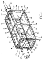
- the apparatus shown therein comprises a flexible bag 10 made of transparent plastics material, e.g. polyethylene, and a cage 11 for supporting the bag 10 clear of an area of a pipe 12 to be stripped.
- a flexible bag 10 made of transparent plastics material, e.g. polyethylene
- a cage 11 for supporting the bag 10 clear of an area of a pipe 12 to be stripped.
- the bag 10 comprises a body portion 10 a and two sleeves 10 b separated from one another by the body portion 10 a .
- An openable seam 13 extends along the length of each sleeve 10 b and between the sleeves along the top of the body portion 10 a .
- the seam 13 is closed by an air-tight (or substantially air-tight) plastics sliding clasp fastener 14.
- Tags 15 are attached to the external surface of the bag 10 and the tags 15 together with the plastics material of the bag define sleeves 16 for receiving parts of the cage 11.
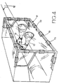
- the bag 10 also has two hand receivable pockets 17, which extend into the bag 10 and which are preferably in the shape of gauntlets as shown in Figure 4, a vacuum connector 18, and a water supply connector 19, all welded to the bag.
- the cage 11 comprises a plurality of rigid tubes, which may be box-section tubes 20, and a plurality of connectors 21, 22, 23 and 24 (see Figures 3 a to 3 d ).
- the cage 11 is made up of three rectangular frame sections 11 a , 11 b and 11 c spaced apart in the direction of the longitudinal extent of the pipe 12 and joined one to another by four tubes 20.
- the central frame section 11 b is itself made up of four tubes 20 joined together at the four corners of the frame by connectors 21 (see Figure 3 a ) having a body part 21 a and four projections 21 b - 21 e , the projections 21 b and 21 c being push-fitted in the ends of two tubes 20 of the frame section 11 b and the projections 21 d and 21 e being push-fitted in the ends of two tubes 20 connected respectively to the frame sections 11 a and 11 c .
- the frame sections 11 a and 11 c are each made up of four outer tubes 20 which are joined together at the corners by connectors 22 (see Figure 3 b ) having a body part 22 a and three projections 22 b - 22 d , and two short inner tubes 20.
- the inner tubes 20 extend between respective connectors 24 (see Figure 3 d ) on the two vertical outer tubes 20 and the connector 23 (see Figure 3 c ) on the uppermost outer horizontal tube 20, to provide within the upper end of the rectangular frame section an inverted V-shaped support 25 which rests on the pipe 12 to support the uppermost tube 20 clear of the pipe 12.
- the connectors 23 and 24 each include a sleeve 23 a and 24 a , respectively which is slidable over an outer tube 20, and connector 23 has two projections 23 b and 23 c which are push-fitted in ends of the two inner short tubes 20, whereas each connector 24 has a single projection 24 b which is push-fitted in the other end of a respective short inner tube 20.
- the bag 10 When it is desired to strip insulation from an area of a pipe 12, the bag 10 is mounted on the pipe from below and the seam 13 is closed by the sliding clasp fastener 14. The sleeves 10 b are then each folded over and sealed to the pipe 12 by tape 26.
- the cage After mounting the bag 10 on the pipe 12, the cage is assembled and during assembly many of the tubes 20 are passed through respective sleeves 16 on the bag 10 so that the body portion 10 a of the bag 10 is supported by the cage 11 clear of the pipe 12.
- a source of negative pressure e.g. an "H" type vacuum cleaner or vacuum interceptor is connected to the connector 18.
- the asbestos cladding on the pipe 12 is then removed using one or more tools (not shown) contained within the bag 10, access to the tools being gained by the hands of an operative being placed in the hand receiving pockets or gauntlets 17.
- a water jet can be connected to the connector 19.
- the bag 10 and cage 11 can be of any desired size to suit the dimensions of a pipe or other elongate member to be stripped and can be used to remove not only asbestos but also other harmful materials.
- the apparatus can be used to strip vertical as well as horizontal pipes, but in this case it is desirable to provide an additional hand receivable pocket in the bag 10 on the side thereof opposite to the pockets 17.
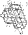
- the apparatus may also be used to strip T-junction pipes as shown in Figure 2 and in this case the bag 10' must be provided with a third sleeve 10 c which is joined to each sleeve 10 b by an openable seam. Also, in this case the cage 11' is of T-shaped construction and the bag 10' has two pairs of hand receivable pockets 17 a and 17 b , respectively.
- the bag 10, 10' need be transparent; it could instead just have one or more transparent windows so that an operative can see to strip the asbestos from the pipe.
- a main part of the bag could for example be of "Valeron", a very strong, but not optically transparent, plastics material available from Van Leer Flexibles Ltd., of Poole, Dorset, England, and the transparent window or windows could be of polyethylene.
- the slidable clasp fastener could be replaced by any other appropriate fastener, such as a hook and eye fastener of the type sold under the name "Velcro" (RTM).
Landscapes
- Working Measures On Existing Buildindgs (AREA)
- Processing Of Solid Wastes (AREA)
- Cleaning In General (AREA)
- Electrical Discharge Machining, Electrochemical Machining, And Combined Machining (AREA)
- Prevention Of Fouling (AREA)
Claims (11)
- Vorrichtung zur Entfernung von Asbest oder anderer schädlicher Materie von Rohrleitungen (12), mit einem flexiblen Sack (10), welcher wenigstens teilweise aus transparentem Kunststoffmaterial hergestellt ist und, welcher auf die Rohrleitung montiert werden kann, und einem Käfig (11), um den Sack frei auf einem zu schälenden Rohrleitungsbereich zu tragen, wobei der Käfig aus mehreren Teilen besteht, welche lösbar miteinander verbunden sind, so dass sie um die Rohrleitung herum zusammengebaut werden können, dadurch gekennzeichnet, dass der Sack zwei schlauchförmige Teile (10a,10b), welche mit der Rohrleitung in Abstand zueinander abgedichtet werden können und eine zu öffnende Naht (13), welche sich entlang und zwischen den beiden schlauchförmigen Teilen erstreckt, hat, und der Käfig selbst Tragmittel (25) hat, mit Hilfe derer der Käfig von der Rohrleitung, von welcher der Asbest oder die schädliche Materie zu entfernen ist, getragen werden kann.
- Vorrichtung nach Anspruch 1, in welcher die Naht mittels Gleitklammerbefestigungsmitteln (14) verschliessbar ist.
- Vorrichtung nach Anspruch 1 oder 2, bei welcher der Sack auf seiner Aussenfläche mit Mitteln zum Befestigung des Sackes am Käfig versehen ist.
- Vorrichtung nach Anspruch 3, bei welcher die Befestigungsmittel Oesen sind, welche zusammen mit dem Sack Schläuche (16) zur Aufnahme individueller Teile des Käfigs bilden.
- Vorrichtung nach einem der Ansprüche 1 bis 4, bei welcher der Sack zwei Taschen (17) zur Aufnahme einer Hand hat, welche Zugang zum Arbeiten zu einem Rohrleitungsbereich im Sack ermöglichen.
- Vorrichtung nach Anspruch 5, bei welcher die Taschen die Form von Handschuhen haben.
- Vorrichtung nach einem der Ansprüche 1 bis 6, bei welcher der Sack einen Vakuumanschluss (18) hat, um eine Quelle negativen Drucks an das Innere des Sackes anzuschliessen.
- Vorrichtung nach einem der Ansprüche 1 bis 7, bei welcher der Sack einen Wasseranschluss (19) hat, welcher die Besprühung des die Rohrleitung umgebenden Asbestes mit Wasser ermöglicht.
- Verfahren zur Entfernung von Asbest oder anderer schädlicher Materie von Rohrleitungen, welche eine Vorrichtung nach einem der vorangehenden Ansprüche verwendet, mit den Verfahrensschritten des Aufbauens des flexiblen Sackes auf der Rohrleitung, des Zusammenbauens des Käfigs auf der Rohrleitung, des Befestigen des Sackes an dem Käfig, des Abdichtens des Käfigs gegenüber der Rohrleitung und des Abstreifens des Asbestes oder anderer schädlicher Materie von der Rohrleitung mit Hilfe eines oder mehrere im Sack befindlicher Werkzeuge.
- Verfahren nach Anspruch 9, bei welchem das Innere des Sackes mit einer Quelle negativen Druckes während des Abstreifvorgangs verbunden ist.
- Verfahren nach Anspruch 9 oder 10, bei welchem der Asbest vor dem Abstreifen vom Rohr benetzt wird.
Applications Claiming Priority (3)
| Application Number | Priority Date | Filing Date | Title |
|---|---|---|---|
| GB888828693A GB8828693D0 (en) | 1988-12-08 | 1988-12-08 | Apparatus for use in & method of removing asbestos |
| GB8828693 | 1988-12-08 | ||
| PCT/GB1989/001450 WO1990006190A1 (en) | 1988-12-08 | 1989-12-05 | Apparatus for use in and a method of removing asbestos |
Publications (2)
| Publication Number | Publication Date |
|---|---|
| EP0447480A1 EP0447480A1 (de) | 1991-09-25 |
| EP0447480B1 true EP0447480B1 (de) | 1994-08-31 |
Family
ID=10648189
Family Applications (1)
| Application Number | Title | Priority Date | Filing Date |
|---|---|---|---|
| EP90900921A Expired - Lifetime EP0447480B1 (de) | 1988-12-08 | 1989-12-05 | Gerät und verfahren zum entfernen von asbest |
Country Status (8)
| Country | Link |
|---|---|
| EP (1) | EP0447480B1 (de) |
| JP (1) | JPH04502272A (de) |
| AT (1) | ATE110597T1 (de) |
| AU (1) | AU622747B2 (de) |
| CA (1) | CA2004577A1 (de) |
| DE (1) | DE68917936D1 (de) |
| GB (2) | GB8828693D0 (de) |
| WO (1) | WO1990006190A1 (de) |
Families Citing this family (13)
| Publication number | Priority date | Publication date | Assignee | Title |
|---|---|---|---|---|
| GB2242517B (en) * | 1990-02-01 | 1993-12-08 | Conoco Inc | Reactor vessel discharge |
| DE4041788C1 (de) * | 1990-12-24 | 1992-04-02 | Herbert 8502 Zirndorf De Hohenleitner | |
| DE4134486A1 (de) * | 1991-10-18 | 1993-04-22 | Gta Gmbh | Schnellabschottung zur entsorgung von kontaminierten kleingeraeten und gegenstaenden durch eine unterdruck-abschott-box ohne persoenliche schutzausruestung |
| GB2349933B (en) * | 1999-05-12 | 2003-05-14 | Vauxhall Motors Ltd | Apparatus for treating elongate members |
| JP4169968B2 (ja) * | 2001-11-19 | 2008-10-22 | 株式会社マツイ・エス・ディ・アイ | エアーフィルタ清掃装置 |
| JP4754420B2 (ja) * | 2006-07-05 | 2011-08-24 | 株式会社Nttファシリティーズ | 建材撤去装置 |
| DE102009009774B4 (de) * | 2009-02-20 | 2011-05-26 | E.On Kernkraft Gmbh | Abschirmung zum Schutz gegen Korpuskularstrahlung |
| GB2470186B (en) * | 2009-05-11 | 2012-10-24 | Sts Resources & Technology Ltd | Apparatus and method for the removal of gaseous fluids from hot work environments |
| JP5600908B2 (ja) * | 2009-08-31 | 2014-10-08 | 株式会社大林組 | 有害物質含有部材の除去方法、及び、有害物質含有部材の除去装置 |
| JP5600909B2 (ja) * | 2009-08-31 | 2014-10-08 | 株式会社大林組 | 有害物質含有部材が付着した長尺部材の解体工法 |
| JP6641089B2 (ja) * | 2015-02-25 | 2020-02-05 | 株式会社環境技術研究所 | アスベスト材工事用作業ボックス |
| GB2552196A (en) * | 2016-07-13 | 2018-01-17 | Claverend Innovations Ltd | Enclosure |
| JP7635950B1 (ja) * | 2024-07-09 | 2025-02-26 | 一般社団法人クリーンレーザー工法協会 | 密閉型粉塵回収方法 |
Family Cites Families (8)
| Publication number | Priority date | Publication date | Assignee | Title |
|---|---|---|---|---|
| US3051163A (en) * | 1957-05-01 | 1962-08-28 | Univ Notre Dame Du Lac | Isolating device |
| US3057163A (en) * | 1961-03-24 | 1962-10-09 | Bahco Ab | Hydraulic pressure-multipliers |
| US4505190A (en) * | 1982-04-19 | 1985-03-19 | Nuclear & Environmental Protection, Inc. | Portable maintenance exhaust hood |
| GB2168475B (en) * | 1984-12-14 | 1988-11-23 | Asbestech Limited | An asbestos dust/fibre removal system |
| GB2173143B (en) * | 1985-04-04 | 1989-10-04 | Atkinson William F | Enclosure device. |
| WO1987006162A1 (en) * | 1986-04-16 | 1987-10-22 | Bartimote John K | Material handling apparatus and method |
| US4783129A (en) * | 1987-01-07 | 1988-11-08 | Jacobson Earl Bruce | Hazardous waste glove bag removal system |
| US4712270A (en) * | 1987-02-02 | 1987-12-15 | Hako Minuteman, Inc. | Brake drum encapsulator |
-
1988
- 1988-12-08 GB GB888828693A patent/GB8828693D0/en active Pending
-
1989
- 1989-12-05 AU AU47415/90A patent/AU622747B2/en not_active Ceased
- 1989-12-05 AT AT90900921T patent/ATE110597T1/de active
- 1989-12-05 GB GB8927454A patent/GB2226878B/en not_active Expired - Lifetime
- 1989-12-05 JP JP2501111A patent/JPH04502272A/ja active Pending
- 1989-12-05 WO PCT/GB1989/001450 patent/WO1990006190A1/en not_active Ceased
- 1989-12-05 DE DE68917936T patent/DE68917936D1/de not_active Expired - Lifetime
- 1989-12-05 EP EP90900921A patent/EP0447480B1/de not_active Expired - Lifetime
- 1989-12-05 CA CA002004577A patent/CA2004577A1/en not_active Abandoned
Also Published As
| Publication number | Publication date |
|---|---|
| JPH04502272A (ja) | 1992-04-23 |
| AU4741590A (en) | 1990-06-26 |
| WO1990006190A1 (en) | 1990-06-14 |
| EP0447480A1 (de) | 1991-09-25 |
| GB8927454D0 (en) | 1990-02-07 |
| GB8828693D0 (en) | 1989-01-11 |
| GB2226878A (en) | 1990-07-11 |
| DE68917936D1 (de) | 1994-10-06 |
| AU622747B2 (en) | 1992-04-16 |
| GB2226878B (en) | 1992-09-23 |
| ATE110597T1 (de) | 1994-09-15 |
| CA2004577A1 (en) | 1990-06-08 |
Similar Documents
| Publication | Publication Date | Title |
|---|---|---|
| AU622747B2 (en) | Apparatus for use in and a method of removing asbestos | |
| US4820000A (en) | Glove bag waste removal system for asbestos impregnated brakes | |
| AU2144088A (en) | Adjustable reusable fitting assembly for reinforced hose | |
| GB2215656A (en) | Containment apparatus. | |
| GB2296426B (en) | A vacuum cleaner with damp cloth apparatus | |
| GB2118263B (en) | Telescopic pipe joints | |
| EP0724788A1 (de) | Kern mit vorgestrecktem rohr | |
| JPH08280602A (ja) | カバー式内視鏡 | |
| SG45284G (en) | Reusable type hose end fitting | |
| AU548873B2 (en) | Device for the assembly of two struts by intercalation of a perpendicular support | |
| FR2699613B1 (fr) | Accessoire de maintien provisoire à faible distance d'une feuille souple à tendre entre deux supports. | |
| DE69529964D1 (de) | Biegsame Röhrenfuge | |
| WO2024246775A1 (en) | System and methods for deploying end effector of a collaborative robot in a glovebox | |
| GB2092698B (en) | A joint device for connecting together hollow frame | |
| AU8848582A (en) | Clamps and methods for connecting flexible sheet to tubular frames | |
| IT1189418B (it) | Morsetto a telaio aperto per apparecchi di manovra elettrici | |
| ATA240879A (de) | Rohrfoermiger abscheider fuer fluessige und feste verunreinigungen aus einer fluessigkeit | |
| JP2999629B2 (ja) | 配電線作業用マニピュレータの絶縁アーム | |
| AU7865894A (en) | Separator for removing impurities from a fluid | |
| ZA824838B (en) | Hose coupling for multi-walled hoses | |
| GB9010189D0 (en) | Aerial cable separating tool | |
| JPS5563085A (en) | Joint for glass tube or the like | |
| KR950026658U (ko) | 진공청소기의 호스 고정장치 | |
| HU9302291D0 (en) | Joint for vacuum cleaner | |
| KR940002697U (ko) | 진공청소기용 흡입관의 잔류액 회수장치 |
Legal Events
| Date | Code | Title | Description |
|---|---|---|---|
| PUAI | Public reference made under article 153(3) epc to a published international application that has entered the european phase |
Free format text: ORIGINAL CODE: 0009012 |
|
| 17P | Request for examination filed |
Effective date: 19910604 |
|
| AK | Designated contracting states |
Kind code of ref document: A1 Designated state(s): AT BE DE FR IT NL SE |
|
| 17Q | First examination report despatched |
Effective date: 19921120 |
|
| GRAA | (expected) grant |
Free format text: ORIGINAL CODE: 0009210 |
|
| AK | Designated contracting states |
Kind code of ref document: B1 Designated state(s): AT BE DE FR IT NL SE |
|
| PG25 | Lapsed in a contracting state [announced via postgrant information from national office to epo] |
Ref country code: BE Effective date: 19940831 Ref country code: AT Effective date: 19940831 Ref country code: IT Free format text: LAPSE BECAUSE OF FAILURE TO SUBMIT A TRANSLATION OF THE DESCRIPTION OR TO PAY THE FEE WITHIN THE PRESCRIBED TIME-LIMIT;WARNING: LAPSES OF ITALIAN PATENTS WITH EFFECTIVE DATE BEFORE 2007 MAY HAVE OCCURRED AT ANY TIME BEFORE 2007. THE CORRECT EFFECTIVE DATE MAY BE DIFFERENT FROM THE ONE RECORDED. Effective date: 19940831 Ref country code: NL Effective date: 19940831 Ref country code: FR Effective date: 19940831 |
|
| REF | Corresponds to: |
Ref document number: 110597 Country of ref document: AT Date of ref document: 19940915 Kind code of ref document: T |
|
| REF | Corresponds to: |
Ref document number: 68917936 Country of ref document: DE Date of ref document: 19941006 |
|
| PG25 | Lapsed in a contracting state [announced via postgrant information from national office to epo] |
Ref country code: SE Effective date: 19941130 |
|
| PG25 | Lapsed in a contracting state [announced via postgrant information from national office to epo] |
Ref country code: DE Effective date: 19941201 |
|
| EN | Fr: translation not filed | ||
| NLV1 | Nl: lapsed or annulled due to failure to fulfill the requirements of art. 29p and 29m of the patents act | ||
| PLBE | No opposition filed within time limit |
Free format text: ORIGINAL CODE: 0009261 |
|
| STAA | Information on the status of an ep patent application or granted ep patent |
Free format text: STATUS: NO OPPOSITION FILED WITHIN TIME LIMIT |
|
| 26N | No opposition filed |