EP0447500B1 - Part-lined disc brake - Google Patents
Part-lined disc brake Download PDFInfo
- Publication number
- EP0447500B1 EP0447500B1 EP90909699A EP90909699A EP0447500B1 EP 0447500 B1 EP0447500 B1 EP 0447500B1 EP 90909699 A EP90909699 A EP 90909699A EP 90909699 A EP90909699 A EP 90909699A EP 0447500 B1 EP0447500 B1 EP 0447500B1
- Authority
- EP
- European Patent Office
- Prior art keywords
- brake
- housing
- spot
- disc
- type disc
- Prior art date
- Legal status (The legal status is an assumption and is not a legal conclusion. Google has not performed a legal analysis and makes no representation as to the accuracy of the status listed.)
- Expired - Lifetime
Links
- 238000013016 damping Methods 0.000 claims description 7
- 238000007789 sealing Methods 0.000 claims description 2
- 230000000717 retained effect Effects 0.000 claims 2
- 230000000284 resting effect Effects 0.000 claims 1
- 230000001681 protective effect Effects 0.000 description 7
- 230000005484 gravity Effects 0.000 description 4
- 239000000463 material Substances 0.000 description 4
- 229910001141 Ductile iron Inorganic materials 0.000 description 3
- 229920002943 EPDM rubber Polymers 0.000 description 2
- 238000005266 casting Methods 0.000 description 2
- 229910001060 Gray iron Inorganic materials 0.000 description 1
- 238000009825 accumulation Methods 0.000 description 1
- 229910052782 aluminium Inorganic materials 0.000 description 1
- XAGFODPZIPBFFR-UHFFFAOYSA-N aluminium Chemical compound [Al] XAGFODPZIPBFFR-UHFFFAOYSA-N 0.000 description 1
- 238000005553 drilling Methods 0.000 description 1
- 229920001971 elastomer Polymers 0.000 description 1
- 238000009434 installation Methods 0.000 description 1
- 230000005855 radiation Effects 0.000 description 1
- 230000002787 reinforcement Effects 0.000 description 1
Images
Classifications
-
- F—MECHANICAL ENGINEERING; LIGHTING; HEATING; WEAPONS; BLASTING
- F16—ENGINEERING ELEMENTS AND UNITS; GENERAL MEASURES FOR PRODUCING AND MAINTAINING EFFECTIVE FUNCTIONING OF MACHINES OR INSTALLATIONS; THERMAL INSULATION IN GENERAL
- F16D—COUPLINGS FOR TRANSMITTING ROTATION; CLUTCHES; BRAKES
- F16D55/00—Brakes with substantially-radial braking surfaces pressed together in axial direction, e.g. disc brakes
- F16D55/02—Brakes with substantially-radial braking surfaces pressed together in axial direction, e.g. disc brakes with axially-movable discs or pads pressed against axially-located rotating members
- F16D55/22—Brakes with substantially-radial braking surfaces pressed together in axial direction, e.g. disc brakes with axially-movable discs or pads pressed against axially-located rotating members by clamping an axially-located rotating disc between movable braking members, e.g. movable brake discs or brake pads
- F16D55/224—Brakes with substantially-radial braking surfaces pressed together in axial direction, e.g. disc brakes with axially-movable discs or pads pressed against axially-located rotating members by clamping an axially-located rotating disc between movable braking members, e.g. movable brake discs or brake pads with a common actuating member for the braking members
- F16D55/225—Brakes with substantially-radial braking surfaces pressed together in axial direction, e.g. disc brakes with axially-movable discs or pads pressed against axially-located rotating members by clamping an axially-located rotating disc between movable braking members, e.g. movable brake discs or brake pads with a common actuating member for the braking members the braking members being brake pads
- F16D55/226—Brakes with substantially-radial braking surfaces pressed together in axial direction, e.g. disc brakes with axially-movable discs or pads pressed against axially-located rotating members by clamping an axially-located rotating disc between movable braking members, e.g. movable brake discs or brake pads with a common actuating member for the braking members the braking members being brake pads in which the common actuating member is moved axially, e.g. floating caliper disc brakes
- F16D55/2265—Brakes with substantially-radial braking surfaces pressed together in axial direction, e.g. disc brakes with axially-movable discs or pads pressed against axially-located rotating members by clamping an axially-located rotating disc between movable braking members, e.g. movable brake discs or brake pads with a common actuating member for the braking members the braking members being brake pads in which the common actuating member is moved axially, e.g. floating caliper disc brakes the axial movement being guided by one or more pins engaging bores in the brake support or the brake housing
- F16D55/227—Brakes with substantially-radial braking surfaces pressed together in axial direction, e.g. disc brakes with axially-movable discs or pads pressed against axially-located rotating members by clamping an axially-located rotating disc between movable braking members, e.g. movable brake discs or brake pads with a common actuating member for the braking members the braking members being brake pads in which the common actuating member is moved axially, e.g. floating caliper disc brakes the axial movement being guided by one or more pins engaging bores in the brake support or the brake housing by two or more pins
-
- F—MECHANICAL ENGINEERING; LIGHTING; HEATING; WEAPONS; BLASTING
- F16—ENGINEERING ELEMENTS AND UNITS; GENERAL MEASURES FOR PRODUCING AND MAINTAINING EFFECTIVE FUNCTIONING OF MACHINES OR INSTALLATIONS; THERMAL INSULATION IN GENERAL
- F16D—COUPLINGS FOR TRANSMITTING ROTATION; CLUTCHES; BRAKES
- F16D55/00—Brakes with substantially-radial braking surfaces pressed together in axial direction, e.g. disc brakes
- F16D55/02—Brakes with substantially-radial braking surfaces pressed together in axial direction, e.g. disc brakes with axially-movable discs or pads pressed against axially-located rotating members
- F16D55/22—Brakes with substantially-radial braking surfaces pressed together in axial direction, e.g. disc brakes with axially-movable discs or pads pressed against axially-located rotating members by clamping an axially-located rotating disc between movable braking members, e.g. movable brake discs or brake pads
- F16D55/224—Brakes with substantially-radial braking surfaces pressed together in axial direction, e.g. disc brakes with axially-movable discs or pads pressed against axially-located rotating members by clamping an axially-located rotating disc between movable braking members, e.g. movable brake discs or brake pads with a common actuating member for the braking members
- F16D55/225—Brakes with substantially-radial braking surfaces pressed together in axial direction, e.g. disc brakes with axially-movable discs or pads pressed against axially-located rotating members by clamping an axially-located rotating disc between movable braking members, e.g. movable brake discs or brake pads with a common actuating member for the braking members the braking members being brake pads
- F16D55/226—Brakes with substantially-radial braking surfaces pressed together in axial direction, e.g. disc brakes with axially-movable discs or pads pressed against axially-located rotating members by clamping an axially-located rotating disc between movable braking members, e.g. movable brake discs or brake pads with a common actuating member for the braking members the braking members being brake pads in which the common actuating member is moved axially, e.g. floating caliper disc brakes
-
- F—MECHANICAL ENGINEERING; LIGHTING; HEATING; WEAPONS; BLASTING
- F16—ENGINEERING ELEMENTS AND UNITS; GENERAL MEASURES FOR PRODUCING AND MAINTAINING EFFECTIVE FUNCTIONING OF MACHINES OR INSTALLATIONS; THERMAL INSULATION IN GENERAL
- F16D—COUPLINGS FOR TRANSMITTING ROTATION; CLUTCHES; BRAKES
- F16D65/00—Parts or details
- F16D65/02—Braking members; Mounting thereof
- F16D65/04—Bands, shoes or pads; Pivots or supporting members therefor
- F16D65/092—Bands, shoes or pads; Pivots or supporting members therefor for axially-engaging brakes, e.g. disc brakes
- F16D65/095—Pivots or supporting members therefor
- F16D65/097—Resilient means interposed between pads and supporting members or other brake parts
- F16D65/0973—Resilient means interposed between pads and supporting members or other brake parts not subjected to brake forces
- F16D65/0974—Resilient means interposed between pads and supporting members or other brake parts not subjected to brake forces acting on or in the vicinity of the pad rim in a direction substantially transverse to the brake disc axis
- F16D65/0977—Springs made from sheet metal
-
- F—MECHANICAL ENGINEERING; LIGHTING; HEATING; WEAPONS; BLASTING
- F16—ENGINEERING ELEMENTS AND UNITS; GENERAL MEASURES FOR PRODUCING AND MAINTAINING EFFECTIVE FUNCTIONING OF MACHINES OR INSTALLATIONS; THERMAL INSULATION IN GENERAL
- F16D—COUPLINGS FOR TRANSMITTING ROTATION; CLUTCHES; BRAKES
- F16D65/00—Parts or details
- F16D65/14—Actuating mechanisms for brakes; Means for initiating operation at a predetermined position
- F16D65/16—Actuating mechanisms for brakes; Means for initiating operation at a predetermined position arranged in or on the brake
- F16D65/18—Actuating mechanisms for brakes; Means for initiating operation at a predetermined position arranged in or on the brake adapted for drawing members together, e.g. for disc brakes
-
- F—MECHANICAL ENGINEERING; LIGHTING; HEATING; WEAPONS; BLASTING
- F16—ENGINEERING ELEMENTS AND UNITS; GENERAL MEASURES FOR PRODUCING AND MAINTAINING EFFECTIVE FUNCTIONING OF MACHINES OR INSTALLATIONS; THERMAL INSULATION IN GENERAL
- F16D—COUPLINGS FOR TRANSMITTING ROTATION; CLUTCHES; BRAKES
- F16D55/00—Brakes with substantially-radial braking surfaces pressed together in axial direction, e.g. disc brakes
- F16D2055/0004—Parts or details of disc brakes
- F16D2055/0016—Brake calipers
-
- F—MECHANICAL ENGINEERING; LIGHTING; HEATING; WEAPONS; BLASTING
- F16—ENGINEERING ELEMENTS AND UNITS; GENERAL MEASURES FOR PRODUCING AND MAINTAINING EFFECTIVE FUNCTIONING OF MACHINES OR INSTALLATIONS; THERMAL INSULATION IN GENERAL
- F16D—COUPLINGS FOR TRANSMITTING ROTATION; CLUTCHES; BRAKES
- F16D55/00—Brakes with substantially-radial braking surfaces pressed together in axial direction, e.g. disc brakes
- F16D2055/0004—Parts or details of disc brakes
- F16D2055/0016—Brake calipers
- F16D2055/002—Brake calipers assembled from a plurality of parts
-
- F—MECHANICAL ENGINEERING; LIGHTING; HEATING; WEAPONS; BLASTING
- F16—ENGINEERING ELEMENTS AND UNITS; GENERAL MEASURES FOR PRODUCING AND MAINTAINING EFFECTIVE FUNCTIONING OF MACHINES OR INSTALLATIONS; THERMAL INSULATION IN GENERAL
- F16D—COUPLINGS FOR TRANSMITTING ROTATION; CLUTCHES; BRAKES
- F16D2121/00—Type of actuator operation force
- F16D2121/02—Fluid pressure
Definitions
- the invention relates to a partial-pad disc brake, in particular for motor vehicles, according to the preamble of claim 1.
- a generic partial-pad disc brake is known from DE-AS 28 04 808, which has two brake carrier arms arranged at a distance from one another in the secant direction to the brake disc and brake shoes guided thereon.
- An outer leg of the brake housing which presses the indirectly actuated brake shoe against the brake disc, is provided with a round opening.
- the outer leg is thus divided in two in the secant direction with two fist fingers arranged symmetrically to an axis of symmetry.
- Another generic brake pad disc brake is also known from DE-A-27 01 451.
- the outer leg of the brake housing is designed to be closed, but only covers one relatively small portion of the outer brake shoe and can therefore not ensure a uniform pressure of the brake shoe on the brake disc.
- the invention has for its object to improve an outer leg of a brake housing.
- tangential oblique wear of the outer brake shoe is to be avoided and an axial installation space for the outer leg of a brake housing is to be reduced.
- the outer leg of the fist-like brake housing is closed, so that the recess provided for a tool between the fingers of the outer leg known from the prior art is filled with casting. On the one hand, this allows the radial length of the outer leg to be reduced and the axial extent of the outer leg to be reduced overall. Furthermore, noise reduction when the brake is actuated is advantageously achieved.
- This connects the two fingers of the outer leg in an integrated design.
- the lower edge of the outer leg extends at a constant radial distance from the disk-shaped circumferential contour of the brake disk. This results in an advantageously uniform pressure distribution on the brake shoe over the circumference of the brake shoe and there is an advantageously uniform cast distribution for the outer leg. Ribs running in the circumferential direction on the outer side of the outer leg advantageously serve to dissipate frictional heat.
- a lifting tooth projecting in the secant direction engages under one of the brake support arms, so that lifting out of the brake housing in the radial direction to the outside is advantageously prevented.
- the brake shoes are supported radially outside the circumference of the brake disc on the supporting parts, so that the brake carrier is advantageously made in one piece with the steering knuckle as an integrated steering knuckle.
- a simple band assembly is achieved because after installing the brake disc, the brake shoes can be suspended on the integrated steering knuckles and then the brake housing can be fitted from above over the brake disc and the brake shoes and screwed onto the steering knuckle.
- radially outward projections of the brake carrier arms engage in grooves provided on the brake shoe ends, so that, at least with higher brake application forces, the frictional force occurring on the brake shoe can advantageously be transmitted to both brake carrier arms, so that the force is distributed over two arms.
- the brake housing is advantageously supported in the region of its bridge section at tangential brake shoe ends of the outer brake shoe in the secant direction, so that on the one hand the brake housing cannot migrate in the circumferential direction and on the other hand the brake shoe is reinforced in the circumferential direction by the intermediate bridge section.
- the same brake shoes are provided on the piston and rim sides for the disc brake, so that the inner and outer brake shoes can be exchanged without problems and the brake shoes cannot be mixed up when installing new brake shoes.
- a central spring is held in a shaft of the brake housing and braces the brake shoes between the carrier arms and the brake housing, so that the brake shoes are held without rattling.
- the inner brake shoe is held by a three-finger clip projecting into the piston on the piston and thus on the brake housing, so that the inner brake shoe can be placed together with the brake housing on the brake disc and mounted on the steering knuckle.
- elastic damping sleeves are used in guide bores of the brake housing, which support the brake housing in an elastically flexible manner on guide bolts fastened in the brake carrier.
- longitudinal ribs extend in the axial direction over the bridge section of the brake housing, so that an expansion of the brake housing is at least partially prevented when the brake is actuated, because the longitudinal ribs of the bridge section reinforce the cast brake housing at this point.
- the brake housing is designed in two parts and in an inner and an outer part in a radial plane offset with respect to the brake disk towards the actuating device cut the brake housing. This ensures that the actuating housing can be machined independently of the outer leg, so that the cylinder bore for the piston can be drilled into the actuating housing without major tooling.
- Different materials can be used for both parts, e.g. aluminum and nodular cast iron (GGG, spheroidal graphite cast iron) or gray cast iron (GG) and nodular cast iron, in order to advantageously save weight.
- the flange section is axially placed on the brake housing, so that the inner and outer parts can advantageously be screwed together with screws, the screw heads protruding toward the center of the vehicle and the thread protruding into a reinforced outer part of the brake housing, which due to the radially expanding rim can be achieved at this point.
- the brake housing is made in one piece and closed pressure-tight by a cover and a sealing ring arranged between the cover and the brake housing, so that the cylinder bore can be drilled with simple tools from the side of the brake housing facing away from the outer leg.
- the circular cover can advantageously be used in such a way that the hose connection of the cover can be adjusted over 360 ° so that the hoses to be connected can be brought from different locations for different vehicle types. Different lids with hose connections different in azimuth angle can also be used advantageously. In the one-piece embodiment, material and thus weight are saved.
- the inner leg essentially has an actuating housing with a piston-cylinder unit, on which a radially extending flange is placed. Ribs are placed on the flange, which serve for reinforcement and advantageously prevent the brake housing from expanding, since the ribs extend radially from the actuating housing over the flange.
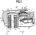
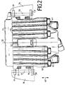
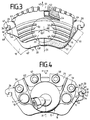
- FIG. 1 to 4 show a partial lining disc brake 1 with a U-shaped brake housing 2.
- a bolt 3 is screwed into a brake carrier 4 and covered by a protective sleeve 5 which is axially connected to the brake carrier 4 by the bolt 3 is set.
- the bolt 3 and the protective sleeve 5 extend through a guide bore 6 of the brake housing 2.
- An elastic guide and damping sleeve 7 surrounds the protective sleeve 5 and, with the aid of its ribs 8, centers the bolt 3 in the center of the guide bore 6 of the brake housing 2.
- An axial extension 9 of the damping sleeve 7 serves to receive a protective cap 10.
- the brake housing 2 is mounted symmetrically on the brake carrier 4 by means of two identically constructed guides consisting of the bolt 3 of the protective sleeve 5 and the damping sleeves 7, 11.
- a piston 13 of an actuating device is slidably mounted in a cylinder bore 14.
- the piston 13 presses directly against a carrier plate 15 of a brake shoe 16, which is thus applied with a friction lining 17 against a first side of a brake disk 18.
- a friction lining 19 of a second brake shoe 20 is pressed against the other side of the brake disk 18 via the reaction force of the brake housing 2.
- An outer leg 22 lies against a carrier plate 21 of the brake shoe 20.
- the brake housing 2 essentially consists of the outer leg 22 and a bridge section 23, which form an outer part 24 of the brake housing 2 and the actuating housing 12 and a flange 25 which form an inner part 26 of the brake housing 2.
- Both brake shoes 16, 20 have tangential brake shoe ends 27, 28, 29 and 30, which are identical due to the similarity of the brake shoes 16, 20 and are symmetrical to a plane of symmetry determined by the axes 31, 32.
- the brake shoe ends 27, 29 rest on a radially outwardly projecting shoulder 33 of a first brake carrier arm 34 and the brake shoe ends 28, 30 on a radially projecting shoulder 35 of a second brake carrier arm 36.
- the lugs 33, 35 extend axially over a length such that the opposite ones Brake shoe ends 27, 29 and 28, 30 of both brake shoes 16, 20 rest on the same shoulder 33, 35.
- the brake shoe ends 27, 28, 29, 30 embrace the lugs 33, 35.
- the brake shoe end 27 has a radially inwardly directed groove 37 which is delimited in the circumferential direction by groove surfaces 38, 39 and radially upwards by a base surface 40.
- the base surface 40 lies on the radial shoulder 33 of the brake support arm 34.
- the groove surfaces 38, 39 come into contact with shoulder surfaces 42, 43 of the radial shoulder 33 directed in the secant direction 41, in such a way that pull-push operation is guaranteed, ie that the games in the groove 37 between the neck 33, 35 and the brake shoe end 27, 28, 29, 30 are dimensioned such that the brake shoe 16, 20 first on the inlet side of the brake disc 18 with a brake arm and then on the outlet side with the other brake carrier arm comes into contact.
- the brake shoe 16, 20 is first pulled and then pressed to advantageously ensure uniform friction lining wear.
- a lifting tooth 44 extends in the secant direction 41 from the outer leg 22 of the brake housing 2 and engages under the brake support arm 34, so that lifting out of the brake housing 2 in the radial direction 45 is prevented.
- a contact surface 46 of the lifting tooth 44 which extends in the secant direction 41 and a contact surface 47 of the brake carrier arm 34 which extends in the secant direction 41 come into contact with one another.
- the brake shoe ends 27, 28, 29 and 30 are arranged outside the brake disk circumference 48 of the brake disk 18.
- the outer leg 22 has a lower edge 49, which is at a constant distance 48 'to the brake disc circumference 48 or to the inner circumference 49' of the Brake disc 18 extends.
- a plurality of ribs 50 extending in the circumferential direction 50 ′ are arranged on the leg 22.
- a central spring 52 is arranged in a shaft 51 of the brake housing 2, which is supported on the one hand on the walls 53 delimiting the shaft 51 and on the other hand on a radially outer edge 54 of the brake shoes 16, 20.
- the inner part 26 and the outer part 24 of the brake housing 2 are divided in a tangential plane, which is predetermined by the axes 54 'and 55'.
- the flange 25 is placed axially in the center on the actuating housing 12, so that the bridge section 23 of the outer part 24 can expand over the actuating housing 12 in the radial direction 45 to match a rim contour 55 above the actuating housing 12.
- the bridge section 23 is dimensioned radially so thick that screws 56 to 59 can be screwed into the bridge section 23 with their threaded section 60.
- the screws 56 to 59 pass through a bore 61 of the flange 25.
- longitudinal ribs 61 ', 62 are provided in a radiation pattern starting from the actuating housing 12. Longitudinal ribs 62 extend in the axial direction 62 ′ on the bridge section 23. End faces 63, 64 of the brake shoe ends 29, 30 support the brake housing 2 on its end faces.
- the inner brake shoe 16 is held on the piston 13 by a three-finger clip 67.
- a circumferential center of gravity line 69 extends in the circumferential direction 50 ′ for the outer brake shoe 20, which is evenly overhanged by the outer leg 22 at least over a partial circumference. This advantageously results in a uniform pressure and casting distribution for the outer leg 22.
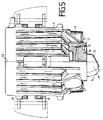
- FIG. 5 shows a one-piece brake housing 2, the actuating housing 12 of which is closed by a cover 70 on the side pointing towards the center of the brake.
- a seal 73 is arranged between the actuating housing 12 and the cover 70, which seals the actuating housing 12 in a pressure-tight manner.
- a hose connection 72 is formed on the cover 70 and points in the direction 73. The hose connection 72 can be rotated in the plane defined by the axes 54 ', 55' during assembly. Furthermore, different covers 70 with hose connections 72 different in azimuth angle 74 can be provided for the assembly.
Landscapes
- Engineering & Computer Science (AREA)
- General Engineering & Computer Science (AREA)
- Mechanical Engineering (AREA)
- Braking Arrangements (AREA)
Abstract
Description
Die Erfindung betrifft eine Teilbelag-Scheibenbremse, insbesondere für Kraftfahrzeuge gemäß dem Oberbegriff des Anspruchs 1.The invention relates to a partial-pad disc brake, in particular for motor vehicles, according to the preamble of claim 1.
Eine gattungsgemäße Teilbelag-Scheibenbremse ist aus der DE-AS 28 04 808 bekannt, die zwei in Sekantenrichtung zur Bremsscheibe in Abstand voneinander angeordnete Bremsträgerarme und daran geführte Bremsbacken aufweist. Ein äußerer Schenkel des Bremsgehäuses, der die indirekt betätigte Bremsbacke gegen die Bremsscheibe drückt, ist mit einer runden Öffnung versehen. Der äußere Schenkel ist somit in Sekantenrichtung zweigeteilt mit zwei zu einer Symmetrieachse symmetrisch angeordneten Faustfingern. Bei Bremsbetätigung werden die einzelnen Finger des Bremsgehäuses trotz einer Materialanhäufung aufgeweitet, so daß ein tangentialer Schrägverschleiß der äußeren Bremsbacke möglich ist.A generic partial-pad disc brake is known from DE-AS 28 04 808, which has two brake carrier arms arranged at a distance from one another in the secant direction to the brake disc and brake shoes guided thereon. An outer leg of the brake housing, which presses the indirectly actuated brake shoe against the brake disc, is provided with a round opening. The outer leg is thus divided in two in the secant direction with two fist fingers arranged symmetrically to an axis of symmetry. When the brake is actuated, the individual fingers of the brake housing are expanded in spite of an accumulation of material, so that tangential oblique wear of the outer brake shoe is possible.
Eine weitere gattungsgemäße Teilbelag-Scheibenbremse ist auch aus der DE-A-27 01 451 bekannt. Bei dieser Scheibenbremse ist der äußere Schenkel des Bremsgehäuses zwar geschlossen ausgeführt, bedeckt aber nur einen relativ kleinen Teilbereich der äußeren Bremsbacke und kann daher einen gleichmäßigen Andruck der Bremsbacke an die Bremsscheibe nicht gewährleisten.Another generic brake pad disc brake is also known from DE-A-27 01 451. In this disc brake, the outer leg of the brake housing is designed to be closed, but only covers one relatively small portion of the outer brake shoe and can therefore not ensure a uniform pressure of the brake shoe on the brake disc.
Der Erfindung liegt die Aufgabe zugrunde, einen äußeren Schenkel eines Bremsgehäuses zu verbessern. Insbesondere soll ein tangentialer Schrägverschleiß der äußeren Bremsbacke vermieden und ein axialer Einbauraum für den äußeren Schenkel eines Bremsgehäuses verringert werden.The invention has for its object to improve an outer leg of a brake housing. In particular, tangential oblique wear of the outer brake shoe is to be avoided and an axial installation space for the outer leg of a brake housing is to be reduced.
Diese Aufgabe wird gemäß den kennzeichnenden Merkmalen des Anspruchs 1 gelöst. Der äußere Schenkel des faustartigen Bremsgehäuses ist geschlossen ausgeführt, so daß die für ein Werkzeug vorgesehene Aussparung zwischen den aus dem Stand der Technik bekannten Faustfingern des äußeren Schenkels mit Guß aufgefüllt ist. Damit kann einerseits die radiale Länge des äußeren Schenkels herabgesetzt und die axiale Ausdehnung des äußeren Schenkels insgesamt verringert werden. Des weiteren wird vorteilhaft eine Geräuschminderung beim Betätigen der Bremse erzielt. Damit sind die beiden Finger des äußeren Schenkels in integrierter Bauweise miteinander verbunden. Die untere Kante des äußeren Schenkels erstreckt sich in einem gleichbleibenden radialen Abstand zu der scheibenförmigen Umfangskontur der Bremsscheibe. Damit wird eine vorteilhaft gleichmäßige Druckverteilung auf die Bremsbacke über den Umfang der Bremsbacke erzielt und es ergibt sich eine vorteilhaft gleichmäßige Gußverteilung für den äußeren Schenkel. In Umfangsrichtung verlaufende Rippen an der äußeren Seite des äußeren Schenkels dienen vorteilhaft zur Abführung von Reibungswärme.This object is achieved in accordance with the characterizing features of claim 1. The outer leg of the fist-like brake housing is closed, so that the recess provided for a tool between the fingers of the outer leg known from the prior art is filled with casting. On the one hand, this allows the radial length of the outer leg to be reduced and the axial extent of the outer leg to be reduced overall. Furthermore, noise reduction when the brake is actuated is advantageously achieved. This connects the two fingers of the outer leg in an integrated design. The lower edge of the outer leg extends at a constant radial distance from the disk-shaped circumferential contour of the brake disk. This results in an advantageously uniform pressure distribution on the brake shoe over the circumference of the brake shoe and there is an advantageously uniform cast distribution for the outer leg. Ribs running in the circumferential direction on the outer side of the outer leg advantageously serve to dissipate frictional heat.
Ein in Sekantenrichtung ragender Aushebezahn untergreift einen der Bremsträgerarme, so daß vorteilhaft ein Ausheben des Bremsgehäuses in Radialrichtung nach außen verhindert ist.A lifting tooth projecting in the secant direction engages under one of the brake support arms, so that lifting out of the brake housing in the radial direction to the outside is advantageously prevented.
Die Bremsbacken sind radial außerhalb des Bremsscheibenumfanges an den Tragteilen abgestützt, so daß vorteilhaft der Bremsträger einteilig mit dem Achssschenkel als integrierter Achsschenkel ausgeführt ist. Dabei wird eine einfache Bandmontage erzielt, weil nach Einbau der Bremsscheibe die Bremsbacken auf den integrierten Achsschenkeln aufhängbar sind und danach das Bremsgehäuse von oben über die Bremsscheibe und die Bremsbacken aufsetzbar und an den Achsschenkel anschraubbar ist.The brake shoes are supported radially outside the circumference of the brake disc on the supporting parts, so that the brake carrier is advantageously made in one piece with the steering knuckle as an integrated steering knuckle. A simple band assembly is achieved because after installing the brake disc, the brake shoes can be suspended on the integrated steering knuckles and then the brake housing can be fitted from above over the brake disc and the brake shoes and screwed onto the steering knuckle.
In vorteilhafter Weise greifen radial nach außen gerichtete Ansätze der Bremsträgerarme in dafür vorgesehene Nuten der Bremsbackenenden ein, so daß zumindest bei höheren Bremsanlegekräften die an der Bremsbacke auftretende Reibungskraft vorteilhaft auf beide Bremsträgerarme übertragbar sind, so daß die Kraft auf zwei Arme verteilt ist.Advantageously, radially outward projections of the brake carrier arms engage in grooves provided on the brake shoe ends, so that, at least with higher brake application forces, the frictional force occurring on the brake shoe can advantageously be transmitted to both brake carrier arms, so that the force is distributed over two arms.
Vorteilhaft ist das Bremsgehäuse im Bereich seines Brückenabschnittes an tangentialen Bremsbackenenden der äußeren Bremsbacke in Sekantenrichtung abgestützt, so daß das Bremsgehäuse einerseits nicht in Umfangsrichtung auswandern kann und andererseits die Bremsbacke in Umfangsrichtung durch den dazwischenliegenden Brückenabschnitt verstärkt ist.The brake housing is advantageously supported in the region of its bridge section at tangential brake shoe ends of the outer brake shoe in the secant direction, so that on the one hand the brake housing cannot migrate in the circumferential direction and on the other hand the brake shoe is reinforced in the circumferential direction by the intermediate bridge section.
In vorteilhafter Weise sind für die Scheibenbremse kolben- wie felgenseitig gleiche Bremsbacken vorgesehen, so daß innere und äußere Bremsbacke problemlos austauschbar sind und die Bremsbacken beim Einbau neuer Bremsbacken nicht verwechselt werden können.Advantageously, the same brake shoes are provided on the piston and rim sides for the disc brake, so that the inner and outer brake shoes can be exchanged without problems and the brake shoes cannot be mixed up when installing new brake shoes.
In einer einfachen Ausgestaltung der Erfindung ist eine Zentralfeder in einen Schacht des Bremsgehäuses gehalten und verspannt die Bremsbacken zwischen den Trägerarmen und dem Bremsgehäuse, so daß die Bremsbacken klapperfrei gehalten sind.In a simple embodiment of the invention, a central spring is held in a shaft of the brake housing and braces the brake shoes between the carrier arms and the brake housing, so that the brake shoes are held without rattling.
In einer anderen einfachen Ausgestaltung der Erfindung ist die innere Bremsbacke von einem in den Kolben ragenden Dreifingerclip an dem Kolben und damit an dem Bremsgehäuse gehalten, so daß die innere Bremsbacke gemeinsam mit dem Bremsgehäuse über die Bremsscheibe aufsetzbar und an den Achsschenkel montierbar ist.In another simple embodiment of the invention, the inner brake shoe is held by a three-finger clip projecting into the piston on the piston and thus on the brake housing, so that the inner brake shoe can be placed together with the brake housing on the brake disc and mounted on the steering knuckle.
In einer vorteilhaften Ausgestaltung der Erfindung sind elastische Dämpfungshülsen (Bushings) in Führungsbohrungen des Bremsgehäuses eingesetzt, die das Bremsgehäuse elastisch nachgiebig an in dem Bremsträger befestigten Führungsbolzen abstützen. Damit wird eine trockene Bushing-Führung erzielt, wobei das Bushing aus gleitfähigem EPDM-Material (Ethylen-Propylen-Dien Rubber) hergestellt ist, also ein gleitfähiges Gummi vorgesehen ist.In an advantageous embodiment of the invention, elastic damping sleeves (bushings) are used in guide bores of the brake housing, which support the brake housing in an elastically flexible manner on guide bolts fastened in the brake carrier. This results in a dry bushing guide, the bushing being made of lubricious EPDM material (ethylene-propylene-diene rubber), that is to say a lubricious rubber is provided.
In vorteilhafter Weise erstrecken sich über den Brückenabschnitt des Bremsgehäuses Längsrippen in Axialrichtung, so daß eine Aufweitung des Bremsgehäuses bei Bremsbetätigung zumindest teilweise verhindert ist, weil die Längsrippen des Brückenabschnittes das Gußbremsgehäuse an dieser Stelle verstärken.Advantageously, longitudinal ribs extend in the axial direction over the bridge section of the brake housing, so that an expansion of the brake housing is at least partially prevented when the brake is actuated, because the longitudinal ribs of the bridge section reinforce the cast brake housing at this point.
In einer ersten einfachen Ausgestaltung der Erfindung ist das Bremsgehäuse zweiteilig ausgeführt und in einer radialen gegenüber der Bremsscheibe zu der Betätigungseinrichtung hin versetzten Ebenen in einen inneren und einen äußeren Teil des Bremsgehäuses geschnitten. Damit wird erreicht, daß das Betätigungsgehäuse unabhängig von dem äußeren Schenkel bearbeitet werden kann, so daß die Zylinderbohrung für den Kolben ohne größeren Werkzeugaufwand in das Betätigungsgehäuse gebohrt werden kann. Dabei können verschiedene Werkstoffe für beide Teile Verwendung finden, also z.B. Aluminium und Sphäroguß (GGG, Kugelgraphitguß) oder Grauguß (GG) und Sphäroguß, um vorteilhaft Gewicht einzusparen.In a first simple embodiment of the invention, the brake housing is designed in two parts and in an inner and an outer part in a radial plane offset with respect to the brake disk towards the actuating device cut the brake housing. This ensures that the actuating housing can be machined independently of the outer leg, so that the cylinder bore for the piston can be drilled into the actuating housing without major tooling. Different materials can be used for both parts, e.g. aluminum and nodular cast iron (GGG, spheroidal graphite cast iron) or gray cast iron (GG) and nodular cast iron, in order to advantageously save weight.
In vorteilhafter Weise ist der Flanschabschnitt axial mittig auf das Bremsgehäuse aufgesetzt, so daß vorteilhaft der innere und äußere Teil mit Schrauben miteinander verschraubbar sind, wobei die Schraubenköpfe zur Fahrzeugmitte hin ragen und das Gewinde in einem verstärkten äußeren Teil des Bremsgehäuses hineinragt, der aufgrund der sich radial erweiternden Felge an dieser Stelle erzielbar ist.Advantageously, the flange section is axially placed on the brake housing, so that the inner and outer parts can advantageously be screwed together with screws, the screw heads protruding toward the center of the vehicle and the thread protruding into a reinforced outer part of the brake housing, which due to the radially expanding rim can be achieved at this point.
In einer weiteren einfachen Ausgestaltung der Erfindung ist das Bremsgehäuse einteilig ausgeführt und von einem Deckel und einem zwischen dem Deckel und dem Bremsgehäuse angeordneten Dichtring druckdicht verschlossen, so daß die Zylinderbohrung mit einfachen Werkzeugen von der dem äußeren Schenkel abgewandten Seite des Bremsgehäuses bohrbar ist. Vorteilhaft ist der kreisförmige Deckel so einsetzbar, daß der Schlauchanschluß des Deckels über 360° verstellbar ist so daß für verschiedene Fahrzeugtypen, die anzuschließenden Schläuche von verschiedenen Orten heranführbar sind. Vorteilhaft können auch verschiedene Deckel mit im Azimutwinkel verschiedenen Schlauchanschlüssen Verwendung finden. Bei der einteiligen Ausführungsform ist Material und damit Gewicht eingespart.In a further simple embodiment of the invention, the brake housing is made in one piece and closed pressure-tight by a cover and a sealing ring arranged between the cover and the brake housing, so that the cylinder bore can be drilled with simple tools from the side of the brake housing facing away from the outer leg. The circular cover can advantageously be used in such a way that the hose connection of the cover can be adjusted over 360 ° so that the hoses to be connected can be brought from different locations for different vehicle types. Different lids with hose connections different in azimuth angle can also be used advantageously. In the one-piece embodiment, material and thus weight are saved.
Der innere Schenkel weist im wesentlichen ein Betätigungsgehäuse mit einer Kolbenzylindereinheit auf, auf das ein sich radial erstreckender Flansch aufgesetzt ist. Auf dem Flansch sind Rippen aufgesetzt, die zur Verstärkung dienen und vorteilhaft einer Aufweitung des Bremsgehäuses vorbeugen, da die Rippen sich strahlenförmig vom Betätigungsgehäuse über den Flansch erstrecken.The inner leg essentially has an actuating housing with a piston-cylinder unit, on which a radially extending flange is placed. Ribs are placed on the flange, which serve for reinforcement and advantageously prevent the brake housing from expanding, since the ribs extend radially from the actuating housing over the flange.
Nachfolgend sind Ausführungsbeispiele der Erfindung anhand von Zeichnungen näher erläutert.Exemplary embodiments of the invention are explained in more detail below with reference to drawings.
Es zeigen
- Fig. 1
- einen Längsschnitt durch eine Teilbelag-Scheibenbremse,
- Fig. 2
- die Scheibenbremse in Draufsicht,
- Fig. 3
- eine teilweise geschnittene Seitenansicht der Teilbelag-Scheibenbremse,
- Fig. 4
- die Rückseite der Scheibenbremse und
- Fig. 5
- eine Teilbelag-Scheibenbremse mit einem Deckel.
- Fig. 1
- a longitudinal section through a partial lining disc brake,
- Fig. 2
- the disc brake in top view,
- Fig. 3
- a partially sectioned side view of the partial lining disc brake,
- Fig. 4
- the rear of the disc brake and
- Fig. 5
- a partial brake disc brake with a cover.
In den Figuren sind gleiche bzw. einander entsprechende Bauteile der Übersichtlichkeit wegen mit gleichen Bezugszeichen versehen.In the figures, identical or corresponding components are provided with the same reference symbols for the sake of clarity.
Fig. 1 bis 4 zeigen eine Teilbelag-Scheibenbremse 1 mit einem U-förmigen Bremsgehäuse 2. Ein Bolzen 3 ist in einem Bremsträger 4 verschraubt und von einer Schutzhülse 5 ummantelt, die durch den Bolzen 3 axial am Bremsträger 4 festgelegt ist. Der Bolzen 3 und die Schutzhülse 5 erstrecken sich durch eine Führungsbohrung 6 des Bremsgehäuses 2. Eine elastische Führungs- und Dämpfungshülse 7 ummantelt die Schutzhülse 5 und zentriert mit Hilfe ihrer Rippen 8 den Bolzen 3 mittig in der Führungsbohrung 6 des Bremsgehäuses 2. Ein axialer Fortsatz 9 der Dämpfungshülse 7 dient zur Aufnahme einer Schutzkappe 10. Das Bremsgehäuse 2 ist über zwei identisch aufgebaute Führungen aus dem Bolzen 3 der Schutz- hülse 5 und den Dämpfungshülsen 7,11 symmetrisch an dem Bremsträger 4 gelagert. In einem Betätigungsgehäuse 12 des Bremsgehäuses 2 ist ein Kolben 13 einer Betätigungseinrichtung in einer Zylinderbohrung 14 verschiebbar gelagert. Der Kolben 13 drückt direkt gegen eine Trägerplatte 15 einer Bremsbacke 16, die somit mit einem Reibbelag 17 gegen eine erste Seite einer Bremsscheibe 18 angelegt wird. Über die Reaktionskraft des Bremsgehäuses 2 wird ein Reibbelag 19 einer zweiten Bremsbacke 20 gegen die andere Seite der Bremsscheibe 18 gedrückt. Dabei legt sich ein äußerer Schenkel 22 gegen eine Trägerplatte 21 der Bremsbacke 20. Das Bremsgehäuse 2 besteht im wesentlichen aus dem äußeren Schenkel 22 und einem Brückenabschnitt 23, die einen äußeren Teil 24 des Bremsgehäuses 2 bilden und dem Betätigungsge- häuse 12 und einem Flansch 25, die einen inneren Teil 26 des Bremsgehäuses 2 bilden. Beide Bremsbacken 16,20 weisen tangentiale Bremsbackenenden 27,28,29 und 30 auf, die wegen der Gleichartigkeit der Bremsbacken 16, 20 identisch ausgebildet und zu einer durch die Achsen 31, 32 bestimmten Symmetrieebene symmetrisch sind. Die Bremsbackenenden 27,29 liegen auf einem radial nach außen vorspringenden Ansatz 33 eines ersten Bremsträgerarmes 34 und die Bremsbackenenden 28,30 auf einem radial vorspringenden Ansatz 35 eines zweiten Bremsträgerarmes 36 auf. Die Ansätze 33,35 erstrecken sich axial über eine solche Länge, daß die sich gegenüberliegenden Bremsbackenenden 27,29 bzw.28, 30 beider Bremsbacken 16,20 auf demselben Ansatz 33,35 aufliegen. Die Bremsbacken- enden 27,28,29,30 umgreifen die Ansätze 33,35. Der Einfach- heit halber und wegen der Gleichartigkeit wird das Umgreifen nur anhand eines Bremsbackenendes 27 näher erläutert. Das Bremsbackenende 27 weist eine radial nach innen gerichtete Nut 37 auf, die in Umfangsrichtung von Nutflächen 38,39 und radial nach oben von einer Basisfläche 40 begrenzt ist. Die Basisfläche 40 liegt auf dem radialen Ansatz 33 des Brems- trägerarmes 34 auf. Die Nutflächen 38,39 treten bei Bremsbe- tätigung mit in Sekantenrichtung 41 gerichteten Ansatz- flächen 42,43 des radialen Ansatzes 33 in Berührung, und zwar so, daß ein Pull-Push (Ziehen-Drücken)-Betrieb gewähr- leistet ist, d.h. daß die Spiele in der Nut 37 zwischen dem Ansatz 33, 35 und dem Bremsbackenende 27, 28, 29, 30 so bemessen sind, daß die Bremsbacke 16, 20 zunächst auf der Einlaufseite der Bremsscheibe 18 mit dem einen Bremsträgerarm und danach auf der Auslaufseite mit dem anderen Bremsträgerarm in Berührung tritt. Dabei wird die Bremsbacke 16, 20 zunächst gezogen und dann gedrückt, um vorteilhaft gleichmäßigen Reibbelagverschleiß zu gewährleisten. Ein Aushebezahn 44 erstreckt sich in Sekantenrichtung 41 von dem äußeren Schenkel 22 des Bremsgehäuses 2 und untergreift den Bremsträgerarm 34, so daß ein Ausheben des Bremsgehäuses 2 in radialer Richtung 45 verhindert wird. Dabei kommen einem sich in Sekantenrichtung 41 ersteckende Anlagefläche 46 des Aushebezahnes 44 und eine sich in Sekantenrichtung 41 erstreckende Anlagefläche 47 des Bremsträgerarmes 34 miteinander in Berührung. Die Bremsbackenenden 27,28,29 und 30 sind außerhalb des Bremsscheibenumfangs 48 der Bremsscheibe 18 angeordnet. Der äußere Schenkel 22 weist eine untere Kante 49 auf, die sich in einem gleichbleibenden Abstand 48' zu dem Bremsscheibenumfang 48 bzw. zu dem inneren Umfang 49' der Bremsscheibe 18 erstreckt. Auf dem Schenkel 22 sind mehrere sich in Umfangsrichtung 50' erstreckende Rippen 50 angeordnet. In einem Schacht 51 des Bremsgehäuses 2 ist eine Zentralfeder 52 angeordnet, die sich einerseits an den Schacht 51 begrenzenden Wänden 53 und andererseits auf einem radial äußeren Rand 54 der Bremsbacken 16,20 abstützt. Der innere Teil 26 und der äußere Teil 24 des Bremsgehäuses 2 sind in einer tangentialen Ebene, die durch die Achsen 54' und 55' vorgegeben ist, geteilt. Dabei ist der Flansch 25 axial mittig auf dem Betätigungsgehäuse 12 aufgesetzt, so daß sich der Brückenabschnitt 23 des äußeren Teiles 24 über dem Betätigungsgehäuse 12 in radialer Richtung 45 einer Felgenkontur 55 anpassend über dem Betätigungsgehäuse 12 aufweiten kann. Dabei ist der Brückenabschnitt 23 radial so dick bemessen, daß Schrauben 56 bis 59 mit ihrem Gewindeabschnitt 60 in dem Brückenabschnitt 23 verschraubbar sind. Die Schrauben 56 bis 59 durchgreifen eine Bohrung 61 des Flansches 25. Auf dem Flansch 25 sind strahlenförmig von dem Betätigungsgehäuse 12 ausgehend Längsrippen 61',62 vorgesehen. Auf dem Brückenabschnitt 23 erstrecken sich in Axialrichtung 62' Längsrippen 62. Stirnflächen 63,64 der Bremsbackenenden 29,30 stützen das Bremsgehäuse 2 an dessen Stirnseiten ab. Die innere Bremsbacke 16 ist von einem Dreifingerclip 67 an dem Kolben 13 gehalten. Ausgehend vom Kolbenschwerpunkt 68 erstreckt sich in Umfangsrichtung 50' eine Umfangsschwerpunktlinie 69 für die äußere Bremsbacke 20, die von dem äußeren Schenkel 22 zumindest über einen Teilumfang gleichmäßig überragt ist. Damit ergibt sich vorteilhaft eine gleichmäßige Druck- und Gußverteilung für den äußeren Schenkel 22.1 to 4 show a partial lining disc brake 1 with a
Fig. 5 zeigt ein einteiliges Bremsgehäuse 2, dessen Betätigungsgehäuse 12 auf der zur Bremsenmitte hin zeigenden Seite von einem Deckel 70 verschlossen ist. Dabei ist zwischen dem Betätigungsgehäuse 12 und dem Deckel 70 eine Dichtung 73 angeordnet, die das Betätigungsgehäuse 12 druckdicht abschließt. An dem Deckel 70 ist ein Schlauchanschluß 72 ausgebildet, der in Richtung 73 weist. Der Schlauchanschluß 72 ist während der Montage in der durch die Achsen 54',55' definierten Ebene verdrehbar. Des weiteren können verschiedene Deckel 70 mit im Azimutwinkel 74 verschiedenen Schlauchanschlüssen 72 für die Montage vorgesehen sein.5 shows a one-
- 11
- Teilbelag-ScheibenbremsePart-pad disc brake
- 22nd
- BremsgehäuseBrake housing
- 33rd
- Bolzenbolt
- 44th
- BremsträgerBrake carrier
- 55
- SchutzhülseProtective sleeve
- 66
- FührungsbohrungPilot hole
- 77
- DämpfungshülseDamping sleeve
- 88th
- RippenRibs
- 99
- FortsatzContinuation
- 1010th
- Schutzkappeprotective cap
- 1111
- DämpfungshülseDamping sleeve
- 1212th
- BetätigungsgehäuseActuator housing
- 1313
- Kolbenpiston
- 1414
- Zylindercylinder
- 1515
- TrägerplatteCarrier plate
- 1616
- BremsbackeBrake shoe
- 1717th
- ReibbelagFriction lining
- 1818th
- BremsscheibeBrake disc
- 1919th
- ReibbelagFriction lining
- 2020th
- BremsbackeBrake shoe
- 2121
- TrägerplatteCarrier plate
- 2222
- äußerer Schenkelouter leg
- 2323
- BrückenabschnittBridge section
- 2424th
- äußerer Teilouter part
- 2525th
- Flanschflange
- 2626
- innerer Teilinner part
- 2727
- BremsbackenendeBrake shoe end
- 2828
- BremsbackenendeBrake shoe end
- 2929
- BremsbackenendeBrake shoe end
- 3030th
- BremsbackenendeBrake shoe end
- 3131
- Achseaxis
- 3232
- Achseaxis
- 3333
- Ansatzapproach
- 3434
- BremsträgerarmBrake carrier arm
- 3535
- Ansatzapproach
- 3636
- BremsträgerarmBrake carrier arm
- 3737
- NutGroove
- 3838
- NutflächeGroove surface
- 3939
- NutflächeGroove surface
- 4040
- BasisflächeBase area
- 4141
- SekantenrichtungSecant direction
- 4242
- AnsatzflächeAttachment area
- 4343
- AnsatzflächeAttachment area
- 4444
- AushebezahnLifting tooth
- 4545
- radiale Richtungradial direction
- 4646
- AnlageflächeContact surface
- 4747
- AnlageflächeContact surface
- 4848
- BremsscheibenumfangBrake disc circumference
- 48'48 '
- Abstanddistance
- 4949
- KanteEdge
- 49'49 '
- innerer Umfanginner scope
- 5050
- RippenRibs
- 50'50 '
- UmfangsrichtungCircumferential direction
- 5151
- SchachtShaft
- 5252
- ZentralfederCentral spring
- 5353
- Wandwall
- 5454
- Randedge
- 54'54 '
- Achseaxis
- 5555
- FelgenkonturRim contour
- 55'55 '
- Achseaxis
- 5656
- Schraubescrew
- 5757
- Schraubescrew
- 5858
- Schraubescrew
- 5959
- Schraubescrew
- 6060
- GewindeabschnittThread section
- 6161
- Bohrungdrilling
- 61'61 '
- LängsrippeLongitudinal rib
- 6262
- LängsrippeLongitudinal rib
- 62'62 '
- AxialrichtungAxial direction
- 6363
- StirnflächeFace
- 6464
- StirnflächeFace
- 6767
- DreifingerclipThree-finger clip
- 6868
- KolbenschwerpunktPiston center of gravity
- 6969
- UmfangsschwerpunktlinieCircumferential center of gravity
- 7070
- Deckelcover
- 7171
- Dichtungpoetry
- 7272
- SchlauchanschlußHose connection
- 7373
- Richtungdirection
- 7474
- AzimutwinkelAzimuth angle
Claims (14)
- A spot-type disc brake, in particular for automotive vehicles, with two brake carrier arms (34, 36) being positioned at a distance from each other in the direction of a secant (41) in respect of the brake disc (18), with two brake shoes (16, 20) resting radially on the brake carrier arms (34, 36), with a brake housing (2) which straddles the brake shoes (16, 20) and the brake disc (18) in a U-shaped manner, with a piston-and-cylinder unit (13, 14) being positioned within a first, internal stem (12) of the brake housing (2) and by means of which the first brake shoe (16) can be urged directly against a first side of the brake disc (18), and with a second, external stem (22) being coupled to the first stem (12) through a bridge section (23) and urging the second, external brake shoe (20) indirectly against the other side of the brake disc (18),
characterized in that the radially internal edge (49) of the external stem (22), which latter has a closed design, extends at a constant radial distance (48') from the circumferential edges (48, 49') of the brake disc (18), and in that ribs (50) are positioned at the external stem (22) which run in circumferential direction (50'). - A spot-type disc brake as claimed in claim 1,
characterized in that the external stem (22) is furnished with a lifting-out tooth (44) projecting in secant direction (41) which makes catch radially internally beneath a brake carrier arm (34). - A spot-type disc brake as claimed in claim 1 or 2,
characterized in that the brake shoes (16, 20) are formed with tangential brake shoe ends (27, 28, 29, 30) which are supported at the brake carrier arms (34, 36) radially outside the brake disc circumference (48). - A spot-type disc brake as claimed in claim 3,
characterized in that the tangential brake shoe ends (27, 28, 29, 30) straddle, with radially inwardly opening grooves (37), radially outwardly directed projections (33, 35) of the brake carrier arms (34, 36) which are sized such relative to each other that the frictional force which occurs at the brake shoe (16, 20) is transmittable to both brake carrier arms (34, 36) at least in the presence of more elevated brake application forces. - A spot-type disc brake as claimed in claim 3 or 4,
characterized in that the tangential ends (29, 30) of the external brake shoe (20) present substantially radially extending front surfaces (63, 64) facing each other at which the brake housing (2) takes support. - A spot-type disc brake as claimed in anyone of the claims 1 to 5,
characterized in that the brake shoes (16, 20) have an identical set-up. - A spot-type disc brake as claimed in anyone of claims 1 to 6,
characterized in that a central spring (52) being retained within an aperture (51) of the brake housing (2) braces both brake shoes (16, 20) against the carrier arms (34, 36). - A spot-type disc brake as claimed in anyone of claims 1 to 5,
characterized in that the internal brake shoe (16) is retained at the piston (13) by a three-finger clip (67) which projects into the piston (13). - A spot-type disc brake as claimed in anyone of claims 1 to 8,
charcterized in that elastic damping bushings (7, 11) are positioned within guide bores (6) of the brake housing (2) which elastically and yieldingly support the brake housing (2) at guide pins (3) which are fixed to the brake carrier (4). - A spot-type disc brake as claimed in anyone of the preceding claims,
characterized in that longitudinal ribs (62) extend in axial direction (62') on the bridge section (23) of the brake housing (2). - A spot-type disc brake as claimed in anyone of the preceding claims,
characterized in that the brake housing (2) is configurated two-part and is sectioned into an internal part (26) and an external part (24) in a radial plane which is offset in respect of the brake disc (18) in the direction of the actuating device (13, 14). - A spot-type disc brake as claimed in claim 11,
characterized in that a substantially radially outwardly extending flange (25) is axially centrically disposed on the actuating housing (12), and in that the internal part (26) and the external part (24) are screwed together. - A spot-type disc brake as claimed in anyone of claims 1 to 10,
characterized in that the cylinder bore (14) of the actuating housing (12) is closed pressure-tightly by a cover lid (70) and by a sealing ring (71) which is interposed between the cover lid (70) and the housing (2). - A spot-type disc brake as claimed in anyone of the preceding claims,
characterized in that longitudinal ribs (61', 62) are positioned on the flange (25), respectively on the brake housing (2) which extend ray-shape from the actuating housing (12) accross the flange (25), respectively accross the brake housing (2).
Applications Claiming Priority (3)
| Application Number | Priority Date | Filing Date | Title |
|---|---|---|---|
| DE3933395A DE3933395A1 (en) | 1989-10-06 | 1989-10-06 | PARTIAL PAD DISC BRAKE |
| DE3933395 | 1989-10-06 | ||
| PCT/EP1990/001050 WO1991005176A1 (en) | 1989-10-06 | 1990-06-30 | Part-lined disc brake |
Publications (2)
| Publication Number | Publication Date |
|---|---|
| EP0447500A1 EP0447500A1 (en) | 1991-09-25 |
| EP0447500B1 true EP0447500B1 (en) | 1994-08-24 |
Family
ID=6390956
Family Applications (1)
| Application Number | Title | Priority Date | Filing Date |
|---|---|---|---|
| EP90909699A Expired - Lifetime EP0447500B1 (en) | 1989-10-06 | 1990-06-30 | Part-lined disc brake |
Country Status (5)
| Country | Link |
|---|---|
| US (1) | US5238090A (en) |
| EP (1) | EP0447500B1 (en) |
| JP (1) | JPH04502058A (en) |
| DE (2) | DE3933395A1 (en) |
| WO (1) | WO1991005176A1 (en) |
Families Citing this family (18)
| Publication number | Priority date | Publication date | Assignee | Title |
|---|---|---|---|---|
| US5259484A (en) * | 1991-02-15 | 1993-11-09 | Nissin Kogyo Co., Ltd. | Reaction force type disc brake |
| JPH0645066Y2 (en) * | 1991-02-15 | 1994-11-16 | 日信工業株式会社 | Reaction force type disc brake |
| JP2555571Y2 (en) * | 1992-08-25 | 1997-11-26 | 日信工業株式会社 | Caliper body of pin slide type vehicle disc brake |
| DE4340453A1 (en) * | 1993-11-27 | 1995-06-01 | Teves Gmbh Alfred | Brake pistons for disc brakes |
| GB9625862D0 (en) | 1996-12-12 | 1997-01-29 | T & N Technology Ltd | Disc brake |
| EP1016804B1 (en) * | 1998-12-31 | 2004-10-06 | Freni Brembo S.p.A. | Cooling device for motor vehicle disk brake |
| US6155650A (en) * | 1999-09-22 | 2000-12-05 | Barger; Robert E. | Anti-dust and cooling cover for brake assembly |
| WO2003058088A1 (en) * | 2002-01-14 | 2003-07-17 | Alcon Components Limited | Cooling arrangement for brake caliper |
| DE10312479B4 (en) | 2003-03-20 | 2007-05-03 | Lucas Automotive Gmbh | disc brake |
| WO2006098766A2 (en) * | 2004-09-17 | 2006-09-21 | Proximex | Incremental data fusion and decision making system and associated method |
| US20080067018A1 (en) * | 2006-09-19 | 2008-03-20 | Alcon Components Limited | Brake disk |
| US8251188B2 (en) * | 2008-09-17 | 2012-08-28 | Akebono Brake Corporation | Disc brake having a pin rail caliper |
| US20100101899A1 (en) * | 2008-10-29 | 2010-04-29 | Finkel Brian G | Brake caliper including heat pipes |
| US8485323B2 (en) | 2010-10-08 | 2013-07-16 | Akebono Brake Corporation | Caliper assembly for disc brake system |
| US20130015023A1 (en) * | 2011-07-13 | 2013-01-17 | Hpev, Inc. | Heat Pipe Cooled Brake System |
| USD685304S1 (en) * | 2013-01-22 | 2013-07-02 | Ashima Ltd. | Brake pad |
| DE102013220634A1 (en) * | 2013-10-14 | 2015-04-30 | Volkswagen Aktiengesellschaft | brake carrier |
| JP6983634B2 (en) * | 2017-11-28 | 2021-12-17 | 日立Astemo株式会社 | Disc brake |
Family Cites Families (26)
| Publication number | Priority date | Publication date | Assignee | Title |
|---|---|---|---|---|
| FR1089618A (en) * | 1953-09-16 | 1955-03-21 | Cie De Pont A Mousson | Advanced brake |
| US3081843A (en) * | 1960-05-25 | 1963-03-19 | Dayton Steel Foundry Co | Improvement in caliper type disk brakes |
| US3251436A (en) * | 1965-03-16 | 1966-05-17 | Dayton Steel Foundry Co | Spot-type disk brake |
| US3388774A (en) * | 1966-09-01 | 1968-06-18 | Bendix Corp | Adjustable bearing means for a disc brake |
| GB1204532A (en) * | 1966-10-01 | 1970-09-09 | Sumitomo Electric Industries | Self-adjusting disc brakes |
| GB1526258A (en) * | 1975-11-06 | 1978-09-27 | Akebono Brake Ind | Disc brake |
| GB1567905A (en) * | 1976-01-17 | 1980-05-21 | Girling Ltd | Disc brakes |
| US4159754A (en) * | 1977-12-05 | 1979-07-03 | Airheart Products, Inc. | Parking brake assembly |
| DE2804808C3 (en) * | 1978-02-04 | 1988-09-29 | Alfred Teves Gmbh, 6000 Frankfurt | Brake shoe holder for a partially lined disc brake, in particular for motor vehicles |
| DE7817030U1 (en) * | 1978-06-07 | 1978-10-19 | Brinke, Hans-Georg, 4600 Dortmund | RIBBED, FOUR-PISTON LIGHT ALLOY BRAKE CALIPER WITH FRAME-SHAPED BRAKE CALIPER SCREW CONNECTION FOR ALL VEHICLES |
| US4220223A (en) * | 1978-08-01 | 1980-09-02 | Kelsey Hayes Co. | Sliding caliper disc brake friction pad assemblies |
| FR2495249B1 (en) * | 1980-11-28 | 1985-12-13 | Valeo | HYDRAULICALLY CONTROLLED BRAKE |
| DE3149883A1 (en) * | 1981-12-16 | 1983-06-23 | Alfred Teves Gmbh, 6000 Frankfurt | FLOATING SADDLE PARTIAL DISC BRAKE |
| DE3338109A1 (en) * | 1983-10-20 | 1985-05-02 | Alfred Teves Gmbh, 6000 Frankfurt | Disc brake for vehicles, especially motor vehicles |
| JPS60109626A (en) * | 1983-11-16 | 1985-06-15 | Nissan Motor Co Ltd | Disk brake |
| DE3421764C2 (en) * | 1984-06-12 | 1993-11-11 | Teves Gmbh Alfred | Part-pad disc brake, in particular for motor vehicles and method for their assembly |
| DE8422260U1 (en) * | 1984-07-26 | 1985-04-25 | Alfred Teves Gmbh, 6000 Frankfurt | Disc brake wrapped around the inside, in particular for motor vehicles |
| DE3514497C2 (en) * | 1985-04-22 | 1995-11-09 | Teves Gmbh Alfred | Protective sleeve for a pin guide of a partial-pad disc brake |
| JPH0312975Y2 (en) * | 1985-12-17 | 1991-03-26 | ||
| DE3608317C2 (en) * | 1986-03-13 | 1995-03-23 | Teves Gmbh Alfred | Part-pad disc brake, in particular for motor vehicles |
| DE3616695C2 (en) * | 1986-05-16 | 1994-06-30 | Teves Gmbh Alfred | Part-pad disc brake |
| US4809825A (en) * | 1987-03-23 | 1989-03-07 | Allied-Signal Inc. | Brake shoe retainer |
| FR2616186B1 (en) * | 1987-06-02 | 1990-10-19 | Bendix France | SPRING FOR DISC BRAKE AND DISC BRAKE PROVIDED WITH SUCH A SPRING |
| JP2779027B2 (en) * | 1988-05-07 | 1998-07-23 | アルフレッド・テヴェス・ゲー・エム・ベーハー | Spot type disc brake |
| DE3815733A1 (en) * | 1988-05-07 | 1989-11-16 | Teves Gmbh Alfred | PARTIAL PAD DISC BRAKE |
| GB2231928B (en) * | 1989-05-26 | 1993-02-17 | Teves Gmbh Alfred | Spot-type disc brake |
-
1989
- 1989-10-06 DE DE3933395A patent/DE3933395A1/en not_active Withdrawn
-
1990
- 1990-06-30 EP EP90909699A patent/EP0447500B1/en not_active Expired - Lifetime
- 1990-06-30 US US07/689,854 patent/US5238090A/en not_active Expired - Fee Related
- 1990-06-30 WO PCT/EP1990/001050 patent/WO1991005176A1/en not_active Ceased
- 1990-06-30 JP JP2509037A patent/JPH04502058A/en active Pending
- 1990-06-30 DE DE59006906T patent/DE59006906D1/en not_active Expired - Fee Related
Also Published As
| Publication number | Publication date |
|---|---|
| US5238090A (en) | 1993-08-24 |
| EP0447500A1 (en) | 1991-09-25 |
| JPH04502058A (en) | 1992-04-09 |
| DE3933395A1 (en) | 1991-04-18 |
| DE59006906D1 (en) | 1994-09-29 |
| WO1991005176A1 (en) | 1991-04-18 |
Similar Documents
| Publication | Publication Date | Title |
|---|---|---|
| EP0447500B1 (en) | Part-lined disc brake | |
| EP0341392B1 (en) | Spot-type disc brake | |
| EP0695401B1 (en) | Steering knuckle arrangement for motor vehicles | |
| EP0190705B1 (en) | Wear indicating device for brake pads | |
| DE60023070T2 (en) | Improved disc brake caliper | |
| EP0380769A1 (en) | Disc brake | |
| EP0341610A1 (en) | Spot-type disc brake | |
| DE4324988A1 (en) | Spot-type disc brake with a multi-part fixed caliper composed of different materials | |
| DE2650767A1 (en) | HYDRAULICALLY ACTUATED DISC BRAKE FOR VEHICLES | |
| DE2165815A1 (en) | Partly lined disc brakes for motor vehicles | |
| EP0242722B1 (en) | Disc brake, especially for motor vehicles | |
| DE3508039A1 (en) | Disc brake with engagement on the inside, in particular for motor vehicles | |
| EP0248024B1 (en) | Partial lining disc brake, especially for motor vehicles | |
| DE19861380A1 (en) | disc brake | |
| DE3921346C2 (en) | Part-pad disc brake | |
| DE3643155C2 (en) | Disc brake with guide pin | |
| EP3511589B1 (en) | Disc brake for commercial vehicles | |
| DE3539602A1 (en) | INTERNAL DISC BRAKE, ESPECIALLY FOR MOTOR VEHICLES | |
| DE4402960C2 (en) | Disc brake | |
| DE3833553A1 (en) | Fixed-calliper spot-type disk brake with an asymmetrically split housing | |
| EP0847504A1 (en) | Partially-lined disk brake with a floating calliper | |
| DE1811666A1 (en) | Disc brakes, especially for vehicles | |
| WO1990010162A1 (en) | Disc brake for motor vehicles | |
| DE1216717B (en) | Partly lined disc brake for the wheels of motor vehicles | |
| DE19540757B4 (en) | Part-pad fixed caliper disc brake, in particular for motor vehicles |
Legal Events
| Date | Code | Title | Description |
|---|---|---|---|
| PUAI | Public reference made under article 153(3) epc to a published international application that has entered the european phase |
Free format text: ORIGINAL CODE: 0009012 |
|
| 17P | Request for examination filed |
Effective date: 19910517 |
|
| AK | Designated contracting states |
Kind code of ref document: A1 Designated state(s): DE FR GB |
|
| 17Q | First examination report despatched |
Effective date: 19921112 |
|
| RAP1 | Party data changed (applicant data changed or rights of an application transferred) |
Owner name: ITT AUTOMOTIVE EUROPE GMBH |
|
| GRAA | (expected) grant |
Free format text: ORIGINAL CODE: 0009210 |
|
| AK | Designated contracting states |
Kind code of ref document: B1 Designated state(s): DE FR GB |
|
| GBT | Gb: translation of ep patent filed (gb section 77(6)(a)/1977) |
Effective date: 19940831 |
|
| REF | Corresponds to: |
Ref document number: 59006906 Country of ref document: DE Date of ref document: 19940929 |
|
| ET | Fr: translation filed | ||
| PLBE | No opposition filed within time limit |
Free format text: ORIGINAL CODE: 0009261 |
|
| STAA | Information on the status of an ep patent application or granted ep patent |
Free format text: STATUS: NO OPPOSITION FILED WITHIN TIME LIMIT |
|
| 26N | No opposition filed | ||
| PGFP | Annual fee paid to national office [announced via postgrant information from national office to epo] |
Ref country code: GB Payment date: 19960520 Year of fee payment: 7 |
|
| PGFP | Annual fee paid to national office [announced via postgrant information from national office to epo] |
Ref country code: FR Payment date: 19960604 Year of fee payment: 7 |
|
| PG25 | Lapsed in a contracting state [announced via postgrant information from national office to epo] |
Ref country code: GB Free format text: LAPSE BECAUSE OF NON-PAYMENT OF DUE FEES Effective date: 19970630 |
|
| GBPC | Gb: european patent ceased through non-payment of renewal fee |
Effective date: 19970630 |
|
| PG25 | Lapsed in a contracting state [announced via postgrant information from national office to epo] |
Ref country code: FR Free format text: LAPSE BECAUSE OF NON-PAYMENT OF DUE FEES Effective date: 19980227 |
|
| REG | Reference to a national code |
Ref country code: FR Ref legal event code: ST |
|
| REG | Reference to a national code |
Ref country code: FR Ref legal event code: ST |
|
| PGFP | Annual fee paid to national office [announced via postgrant information from national office to epo] |
Ref country code: DE Payment date: 19980612 Year of fee payment: 9 |
|
| PG25 | Lapsed in a contracting state [announced via postgrant information from national office to epo] |
Ref country code: DE Free format text: LAPSE BECAUSE OF NON-PAYMENT OF DUE FEES Effective date: 20000503 |