EP0447500B1 - Frein a disque a garniture partielle - Google Patents
Frein a disque a garniture partielle Download PDFInfo
- Publication number
- EP0447500B1 EP0447500B1 EP90909699A EP90909699A EP0447500B1 EP 0447500 B1 EP0447500 B1 EP 0447500B1 EP 90909699 A EP90909699 A EP 90909699A EP 90909699 A EP90909699 A EP 90909699A EP 0447500 B1 EP0447500 B1 EP 0447500B1
- Authority
- EP
- European Patent Office
- Prior art keywords
- brake
- housing
- spot
- disc
- type disc
- Prior art date
- Legal status (The legal status is an assumption and is not a legal conclusion. Google has not performed a legal analysis and makes no representation as to the accuracy of the status listed.)
- Expired - Lifetime
Links
- 238000013016 damping Methods 0.000 claims description 7
- 238000007789 sealing Methods 0.000 claims description 2
- 230000000717 retained effect Effects 0.000 claims 2
- 230000000284 resting effect Effects 0.000 claims 1
- 230000001681 protective effect Effects 0.000 description 7
- 230000005484 gravity Effects 0.000 description 4
- 239000000463 material Substances 0.000 description 4
- 229910001141 Ductile iron Inorganic materials 0.000 description 3
- 229920002943 EPDM rubber Polymers 0.000 description 2
- 238000005266 casting Methods 0.000 description 2
- 229910001060 Gray iron Inorganic materials 0.000 description 1
- 238000009825 accumulation Methods 0.000 description 1
- 229910052782 aluminium Inorganic materials 0.000 description 1
- XAGFODPZIPBFFR-UHFFFAOYSA-N aluminium Chemical compound [Al] XAGFODPZIPBFFR-UHFFFAOYSA-N 0.000 description 1
- 238000005553 drilling Methods 0.000 description 1
- 229920001971 elastomer Polymers 0.000 description 1
- 238000009434 installation Methods 0.000 description 1
- 230000005855 radiation Effects 0.000 description 1
- 230000002787 reinforcement Effects 0.000 description 1
Images
Classifications
-
- F—MECHANICAL ENGINEERING; LIGHTING; HEATING; WEAPONS; BLASTING
- F16—ENGINEERING ELEMENTS AND UNITS; GENERAL MEASURES FOR PRODUCING AND MAINTAINING EFFECTIVE FUNCTIONING OF MACHINES OR INSTALLATIONS; THERMAL INSULATION IN GENERAL
- F16D—COUPLINGS FOR TRANSMITTING ROTATION; CLUTCHES; BRAKES
- F16D55/00—Brakes with substantially-radial braking surfaces pressed together in axial direction, e.g. disc brakes
- F16D55/02—Brakes with substantially-radial braking surfaces pressed together in axial direction, e.g. disc brakes with axially-movable discs or pads pressed against axially-located rotating members
- F16D55/22—Brakes with substantially-radial braking surfaces pressed together in axial direction, e.g. disc brakes with axially-movable discs or pads pressed against axially-located rotating members by clamping an axially-located rotating disc between movable braking members, e.g. movable brake discs or brake pads
- F16D55/224—Brakes with substantially-radial braking surfaces pressed together in axial direction, e.g. disc brakes with axially-movable discs or pads pressed against axially-located rotating members by clamping an axially-located rotating disc between movable braking members, e.g. movable brake discs or brake pads with a common actuating member for the braking members
- F16D55/225—Brakes with substantially-radial braking surfaces pressed together in axial direction, e.g. disc brakes with axially-movable discs or pads pressed against axially-located rotating members by clamping an axially-located rotating disc between movable braking members, e.g. movable brake discs or brake pads with a common actuating member for the braking members the braking members being brake pads
- F16D55/226—Brakes with substantially-radial braking surfaces pressed together in axial direction, e.g. disc brakes with axially-movable discs or pads pressed against axially-located rotating members by clamping an axially-located rotating disc between movable braking members, e.g. movable brake discs or brake pads with a common actuating member for the braking members the braking members being brake pads in which the common actuating member is moved axially, e.g. floating caliper disc brakes
- F16D55/2265—Brakes with substantially-radial braking surfaces pressed together in axial direction, e.g. disc brakes with axially-movable discs or pads pressed against axially-located rotating members by clamping an axially-located rotating disc between movable braking members, e.g. movable brake discs or brake pads with a common actuating member for the braking members the braking members being brake pads in which the common actuating member is moved axially, e.g. floating caliper disc brakes the axial movement being guided by one or more pins engaging bores in the brake support or the brake housing
- F16D55/227—Brakes with substantially-radial braking surfaces pressed together in axial direction, e.g. disc brakes with axially-movable discs or pads pressed against axially-located rotating members by clamping an axially-located rotating disc between movable braking members, e.g. movable brake discs or brake pads with a common actuating member for the braking members the braking members being brake pads in which the common actuating member is moved axially, e.g. floating caliper disc brakes the axial movement being guided by one or more pins engaging bores in the brake support or the brake housing by two or more pins
-
- F—MECHANICAL ENGINEERING; LIGHTING; HEATING; WEAPONS; BLASTING
- F16—ENGINEERING ELEMENTS AND UNITS; GENERAL MEASURES FOR PRODUCING AND MAINTAINING EFFECTIVE FUNCTIONING OF MACHINES OR INSTALLATIONS; THERMAL INSULATION IN GENERAL
- F16D—COUPLINGS FOR TRANSMITTING ROTATION; CLUTCHES; BRAKES
- F16D55/00—Brakes with substantially-radial braking surfaces pressed together in axial direction, e.g. disc brakes
- F16D55/02—Brakes with substantially-radial braking surfaces pressed together in axial direction, e.g. disc brakes with axially-movable discs or pads pressed against axially-located rotating members
- F16D55/22—Brakes with substantially-radial braking surfaces pressed together in axial direction, e.g. disc brakes with axially-movable discs or pads pressed against axially-located rotating members by clamping an axially-located rotating disc between movable braking members, e.g. movable brake discs or brake pads
- F16D55/224—Brakes with substantially-radial braking surfaces pressed together in axial direction, e.g. disc brakes with axially-movable discs or pads pressed against axially-located rotating members by clamping an axially-located rotating disc between movable braking members, e.g. movable brake discs or brake pads with a common actuating member for the braking members
- F16D55/225—Brakes with substantially-radial braking surfaces pressed together in axial direction, e.g. disc brakes with axially-movable discs or pads pressed against axially-located rotating members by clamping an axially-located rotating disc between movable braking members, e.g. movable brake discs or brake pads with a common actuating member for the braking members the braking members being brake pads
- F16D55/226—Brakes with substantially-radial braking surfaces pressed together in axial direction, e.g. disc brakes with axially-movable discs or pads pressed against axially-located rotating members by clamping an axially-located rotating disc between movable braking members, e.g. movable brake discs or brake pads with a common actuating member for the braking members the braking members being brake pads in which the common actuating member is moved axially, e.g. floating caliper disc brakes
-
- F—MECHANICAL ENGINEERING; LIGHTING; HEATING; WEAPONS; BLASTING
- F16—ENGINEERING ELEMENTS AND UNITS; GENERAL MEASURES FOR PRODUCING AND MAINTAINING EFFECTIVE FUNCTIONING OF MACHINES OR INSTALLATIONS; THERMAL INSULATION IN GENERAL
- F16D—COUPLINGS FOR TRANSMITTING ROTATION; CLUTCHES; BRAKES
- F16D65/00—Parts or details
- F16D65/02—Braking members; Mounting thereof
- F16D65/04—Bands, shoes or pads; Pivots or supporting members therefor
- F16D65/092—Bands, shoes or pads; Pivots or supporting members therefor for axially-engaging brakes, e.g. disc brakes
- F16D65/095—Pivots or supporting members therefor
- F16D65/097—Resilient means interposed between pads and supporting members or other brake parts
- F16D65/0973—Resilient means interposed between pads and supporting members or other brake parts not subjected to brake forces
- F16D65/0974—Resilient means interposed between pads and supporting members or other brake parts not subjected to brake forces acting on or in the vicinity of the pad rim in a direction substantially transverse to the brake disc axis
- F16D65/0977—Springs made from sheet metal
-
- F—MECHANICAL ENGINEERING; LIGHTING; HEATING; WEAPONS; BLASTING
- F16—ENGINEERING ELEMENTS AND UNITS; GENERAL MEASURES FOR PRODUCING AND MAINTAINING EFFECTIVE FUNCTIONING OF MACHINES OR INSTALLATIONS; THERMAL INSULATION IN GENERAL
- F16D—COUPLINGS FOR TRANSMITTING ROTATION; CLUTCHES; BRAKES
- F16D65/00—Parts or details
- F16D65/14—Actuating mechanisms for brakes; Means for initiating operation at a predetermined position
- F16D65/16—Actuating mechanisms for brakes; Means for initiating operation at a predetermined position arranged in or on the brake
- F16D65/18—Actuating mechanisms for brakes; Means for initiating operation at a predetermined position arranged in or on the brake adapted for drawing members together, e.g. for disc brakes
-
- F—MECHANICAL ENGINEERING; LIGHTING; HEATING; WEAPONS; BLASTING
- F16—ENGINEERING ELEMENTS AND UNITS; GENERAL MEASURES FOR PRODUCING AND MAINTAINING EFFECTIVE FUNCTIONING OF MACHINES OR INSTALLATIONS; THERMAL INSULATION IN GENERAL
- F16D—COUPLINGS FOR TRANSMITTING ROTATION; CLUTCHES; BRAKES
- F16D55/00—Brakes with substantially-radial braking surfaces pressed together in axial direction, e.g. disc brakes
- F16D2055/0004—Parts or details of disc brakes
- F16D2055/0016—Brake calipers
-
- F—MECHANICAL ENGINEERING; LIGHTING; HEATING; WEAPONS; BLASTING
- F16—ENGINEERING ELEMENTS AND UNITS; GENERAL MEASURES FOR PRODUCING AND MAINTAINING EFFECTIVE FUNCTIONING OF MACHINES OR INSTALLATIONS; THERMAL INSULATION IN GENERAL
- F16D—COUPLINGS FOR TRANSMITTING ROTATION; CLUTCHES; BRAKES
- F16D55/00—Brakes with substantially-radial braking surfaces pressed together in axial direction, e.g. disc brakes
- F16D2055/0004—Parts or details of disc brakes
- F16D2055/0016—Brake calipers
- F16D2055/002—Brake calipers assembled from a plurality of parts
-
- F—MECHANICAL ENGINEERING; LIGHTING; HEATING; WEAPONS; BLASTING
- F16—ENGINEERING ELEMENTS AND UNITS; GENERAL MEASURES FOR PRODUCING AND MAINTAINING EFFECTIVE FUNCTIONING OF MACHINES OR INSTALLATIONS; THERMAL INSULATION IN GENERAL
- F16D—COUPLINGS FOR TRANSMITTING ROTATION; CLUTCHES; BRAKES
- F16D2121/00—Type of actuator operation force
- F16D2121/02—Fluid pressure
Definitions
- the invention relates to a partial-pad disc brake, in particular for motor vehicles, according to the preamble of claim 1.
- a generic partial-pad disc brake is known from DE-AS 28 04 808, which has two brake carrier arms arranged at a distance from one another in the secant direction to the brake disc and brake shoes guided thereon.
- An outer leg of the brake housing which presses the indirectly actuated brake shoe against the brake disc, is provided with a round opening.
- the outer leg is thus divided in two in the secant direction with two fist fingers arranged symmetrically to an axis of symmetry.
- Another generic brake pad disc brake is also known from DE-A-27 01 451.
- the outer leg of the brake housing is designed to be closed, but only covers one relatively small portion of the outer brake shoe and can therefore not ensure a uniform pressure of the brake shoe on the brake disc.
- the invention has for its object to improve an outer leg of a brake housing.
- tangential oblique wear of the outer brake shoe is to be avoided and an axial installation space for the outer leg of a brake housing is to be reduced.
- the outer leg of the fist-like brake housing is closed, so that the recess provided for a tool between the fingers of the outer leg known from the prior art is filled with casting. On the one hand, this allows the radial length of the outer leg to be reduced and the axial extent of the outer leg to be reduced overall. Furthermore, noise reduction when the brake is actuated is advantageously achieved.
- This connects the two fingers of the outer leg in an integrated design.
- the lower edge of the outer leg extends at a constant radial distance from the disk-shaped circumferential contour of the brake disk. This results in an advantageously uniform pressure distribution on the brake shoe over the circumference of the brake shoe and there is an advantageously uniform cast distribution for the outer leg. Ribs running in the circumferential direction on the outer side of the outer leg advantageously serve to dissipate frictional heat.
- a lifting tooth projecting in the secant direction engages under one of the brake support arms, so that lifting out of the brake housing in the radial direction to the outside is advantageously prevented.
- the brake shoes are supported radially outside the circumference of the brake disc on the supporting parts, so that the brake carrier is advantageously made in one piece with the steering knuckle as an integrated steering knuckle.
- a simple band assembly is achieved because after installing the brake disc, the brake shoes can be suspended on the integrated steering knuckles and then the brake housing can be fitted from above over the brake disc and the brake shoes and screwed onto the steering knuckle.
- radially outward projections of the brake carrier arms engage in grooves provided on the brake shoe ends, so that, at least with higher brake application forces, the frictional force occurring on the brake shoe can advantageously be transmitted to both brake carrier arms, so that the force is distributed over two arms.
- the brake housing is advantageously supported in the region of its bridge section at tangential brake shoe ends of the outer brake shoe in the secant direction, so that on the one hand the brake housing cannot migrate in the circumferential direction and on the other hand the brake shoe is reinforced in the circumferential direction by the intermediate bridge section.
- the same brake shoes are provided on the piston and rim sides for the disc brake, so that the inner and outer brake shoes can be exchanged without problems and the brake shoes cannot be mixed up when installing new brake shoes.
- a central spring is held in a shaft of the brake housing and braces the brake shoes between the carrier arms and the brake housing, so that the brake shoes are held without rattling.
- the inner brake shoe is held by a three-finger clip projecting into the piston on the piston and thus on the brake housing, so that the inner brake shoe can be placed together with the brake housing on the brake disc and mounted on the steering knuckle.
- elastic damping sleeves are used in guide bores of the brake housing, which support the brake housing in an elastically flexible manner on guide bolts fastened in the brake carrier.
- longitudinal ribs extend in the axial direction over the bridge section of the brake housing, so that an expansion of the brake housing is at least partially prevented when the brake is actuated, because the longitudinal ribs of the bridge section reinforce the cast brake housing at this point.
- the brake housing is designed in two parts and in an inner and an outer part in a radial plane offset with respect to the brake disk towards the actuating device cut the brake housing. This ensures that the actuating housing can be machined independently of the outer leg, so that the cylinder bore for the piston can be drilled into the actuating housing without major tooling.
- Different materials can be used for both parts, e.g. aluminum and nodular cast iron (GGG, spheroidal graphite cast iron) or gray cast iron (GG) and nodular cast iron, in order to advantageously save weight.
- the flange section is axially placed on the brake housing, so that the inner and outer parts can advantageously be screwed together with screws, the screw heads protruding toward the center of the vehicle and the thread protruding into a reinforced outer part of the brake housing, which due to the radially expanding rim can be achieved at this point.
- the brake housing is made in one piece and closed pressure-tight by a cover and a sealing ring arranged between the cover and the brake housing, so that the cylinder bore can be drilled with simple tools from the side of the brake housing facing away from the outer leg.
- the circular cover can advantageously be used in such a way that the hose connection of the cover can be adjusted over 360 ° so that the hoses to be connected can be brought from different locations for different vehicle types. Different lids with hose connections different in azimuth angle can also be used advantageously. In the one-piece embodiment, material and thus weight are saved.
- the inner leg essentially has an actuating housing with a piston-cylinder unit, on which a radially extending flange is placed. Ribs are placed on the flange, which serve for reinforcement and advantageously prevent the brake housing from expanding, since the ribs extend radially from the actuating housing over the flange.
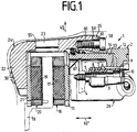
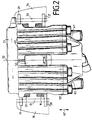
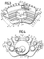
- FIG. 1 to 4 show a partial lining disc brake 1 with a U-shaped brake housing 2.
- a bolt 3 is screwed into a brake carrier 4 and covered by a protective sleeve 5 which is axially connected to the brake carrier 4 by the bolt 3 is set.
- the bolt 3 and the protective sleeve 5 extend through a guide bore 6 of the brake housing 2.
- An elastic guide and damping sleeve 7 surrounds the protective sleeve 5 and, with the aid of its ribs 8, centers the bolt 3 in the center of the guide bore 6 of the brake housing 2.
- An axial extension 9 of the damping sleeve 7 serves to receive a protective cap 10.
- the brake housing 2 is mounted symmetrically on the brake carrier 4 by means of two identically constructed guides consisting of the bolt 3 of the protective sleeve 5 and the damping sleeves 7, 11.
- a piston 13 of an actuating device is slidably mounted in a cylinder bore 14.
- the piston 13 presses directly against a carrier plate 15 of a brake shoe 16, which is thus applied with a friction lining 17 against a first side of a brake disk 18.
- a friction lining 19 of a second brake shoe 20 is pressed against the other side of the brake disk 18 via the reaction force of the brake housing 2.
- An outer leg 22 lies against a carrier plate 21 of the brake shoe 20.
- the brake housing 2 essentially consists of the outer leg 22 and a bridge section 23, which form an outer part 24 of the brake housing 2 and the actuating housing 12 and a flange 25 which form an inner part 26 of the brake housing 2.
- Both brake shoes 16, 20 have tangential brake shoe ends 27, 28, 29 and 30, which are identical due to the similarity of the brake shoes 16, 20 and are symmetrical to a plane of symmetry determined by the axes 31, 32.
- the brake shoe ends 27, 29 rest on a radially outwardly projecting shoulder 33 of a first brake carrier arm 34 and the brake shoe ends 28, 30 on a radially projecting shoulder 35 of a second brake carrier arm 36.
- the lugs 33, 35 extend axially over a length such that the opposite ones Brake shoe ends 27, 29 and 28, 30 of both brake shoes 16, 20 rest on the same shoulder 33, 35.
- the brake shoe ends 27, 28, 29, 30 embrace the lugs 33, 35.
- the brake shoe end 27 has a radially inwardly directed groove 37 which is delimited in the circumferential direction by groove surfaces 38, 39 and radially upwards by a base surface 40.
- the base surface 40 lies on the radial shoulder 33 of the brake support arm 34.
- the groove surfaces 38, 39 come into contact with shoulder surfaces 42, 43 of the radial shoulder 33 directed in the secant direction 41, in such a way that pull-push operation is guaranteed, ie that the games in the groove 37 between the neck 33, 35 and the brake shoe end 27, 28, 29, 30 are dimensioned such that the brake shoe 16, 20 first on the inlet side of the brake disc 18 with a brake arm and then on the outlet side with the other brake carrier arm comes into contact.
- the brake shoe 16, 20 is first pulled and then pressed to advantageously ensure uniform friction lining wear.
- a lifting tooth 44 extends in the secant direction 41 from the outer leg 22 of the brake housing 2 and engages under the brake support arm 34, so that lifting out of the brake housing 2 in the radial direction 45 is prevented.
- a contact surface 46 of the lifting tooth 44 which extends in the secant direction 41 and a contact surface 47 of the brake carrier arm 34 which extends in the secant direction 41 come into contact with one another.
- the brake shoe ends 27, 28, 29 and 30 are arranged outside the brake disk circumference 48 of the brake disk 18.
- the outer leg 22 has a lower edge 49, which is at a constant distance 48 'to the brake disc circumference 48 or to the inner circumference 49' of the Brake disc 18 extends.
- a plurality of ribs 50 extending in the circumferential direction 50 ′ are arranged on the leg 22.
- a central spring 52 is arranged in a shaft 51 of the brake housing 2, which is supported on the one hand on the walls 53 delimiting the shaft 51 and on the other hand on a radially outer edge 54 of the brake shoes 16, 20.
- the inner part 26 and the outer part 24 of the brake housing 2 are divided in a tangential plane, which is predetermined by the axes 54 'and 55'.
- the flange 25 is placed axially in the center on the actuating housing 12, so that the bridge section 23 of the outer part 24 can expand over the actuating housing 12 in the radial direction 45 to match a rim contour 55 above the actuating housing 12.
- the bridge section 23 is dimensioned radially so thick that screws 56 to 59 can be screwed into the bridge section 23 with their threaded section 60.
- the screws 56 to 59 pass through a bore 61 of the flange 25.
- longitudinal ribs 61 ', 62 are provided in a radiation pattern starting from the actuating housing 12. Longitudinal ribs 62 extend in the axial direction 62 ′ on the bridge section 23. End faces 63, 64 of the brake shoe ends 29, 30 support the brake housing 2 on its end faces.
- the inner brake shoe 16 is held on the piston 13 by a three-finger clip 67.
- a circumferential center of gravity line 69 extends in the circumferential direction 50 ′ for the outer brake shoe 20, which is evenly overhanged by the outer leg 22 at least over a partial circumference. This advantageously results in a uniform pressure and casting distribution for the outer leg 22.
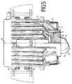
- FIG. 5 shows a one-piece brake housing 2, the actuating housing 12 of which is closed by a cover 70 on the side pointing towards the center of the brake.
- a seal 73 is arranged between the actuating housing 12 and the cover 70, which seals the actuating housing 12 in a pressure-tight manner.
- a hose connection 72 is formed on the cover 70 and points in the direction 73. The hose connection 72 can be rotated in the plane defined by the axes 54 ', 55' during assembly. Furthermore, different covers 70 with hose connections 72 different in azimuth angle 74 can be provided for the assembly.
Landscapes
- Engineering & Computer Science (AREA)
- General Engineering & Computer Science (AREA)
- Mechanical Engineering (AREA)
- Braking Arrangements (AREA)
Abstract
Claims (14)
- Frein à disque à garniture partielle pour véhicules automobiles comprenant deux bras de support (34, 36) du frein disposés à une distance l'un de l'autre, dans le sens de la sécante (41) du disque de frein (18), comprenant deux plaquettes de frein (16, 20), comprenant un carter de frein (2) encadrant selon une forme de U les plaquettes de frein (16, 20) et le disque de frein (18), comprenant une unité à pistoncylindre (13, 14) agencée dans une première branche intérieure (12) du carter de frein (2), grâce à laquelle la première plaquette de frein (16) peut être forcée directement contre une première face du disque de frein (18), et comprenant une seconde branche extérieure (22) reliée, par l'intermédiaire d'une section de pontage (23), à la première branche (12) et forçant la seconde plaquette extérieure (20) du frein indirectement contre l'autre face du disque de frein (18),
caractérisé en ce que
le bord (49) radialement intérieur de la branche extérieure (22) réalisée en branche fermée s'étend le long des bords périphériques (48, 48') du disque de frein (18) à une distance radiale uniforme (48') par rapport à ceux-ci, et en ce que des nervures (50) s'étendant dans le sens de la circonférence sont agencées sur la branche extérieure (22). - Frein à disque à garniture partielle selon la revendication 1, caractérisé en ce que la branche extérieure (22) comporte une dent anti-décrochage (44) saillant dans le sens de la sécante (41), qui s'engage radialement à l'intérieur sous un bras de support (34) du frein.
- Frein à disque à garniture partielle selon l'une des revendications 1 ou 2, caractérisé en ce que les plaquettes de frein (16, 20) comportent des extrémités tangentielles (27, 28, 29, 30) qui s'appuient radialement à l'extérieur de la circonférence (48) du disque de frein sur les bras de support (34, 36) du frein.
- Frein à disque à garniture partielle selon la revendication 3, caractérisé en ce que les extrémités tangentielles (27, 28, 29, 30) des plaquettes de frein entourent, par leurs rainures (37) s'ouvrant radialement vers l'intérieur, des prolongements (33, 35) des bras de support (34, 36), dirigés radialement vers l'extérieur, ces prolongements étant dimensionnés selon une relation l'un par rapport à l'autre, qui fait qu'au moins dans le cas d'efforts élevés d'application des freins, la force de frottement créée au niveau de la plaquette de frein (16, 20) puisse être répartie sur les deux bras de support (34, 36) du frein.
- Frein à disque à garniture partielle selon la revendication 3 ou la revendication 4, caractérisé en ce que les extrémités tangentielles (29, 30) de la plaquette de frein extérieure (20) présentent des faces frontales juxtaposées (63, 64) s'étendant essentiellement dans le sens radial, sur lesquelles s'appuie le carter de frein (2).
- Frein à disque à garniture partielle selon l'une des revendications 1 à 5, caractérisé en ce que les plaquettes de frein (16, 20) sont conçues de façon identique.
- Frein à disque à garniture partielle selon l'une des revendications 1 à 6, caractérisé en ce qu'un ressort central (52) maintenu dans un puits (51) du carter de frein (2) rappelle les deux plaquettes de frein (16, 20) en appui sur les bras de support (34, 36) du frein.
- Frein à disque selon l'une des revendications 1 à 5, caractérisé en ce que la plaquette de frein intérieure (16) est maintenue contre le piston (13) par un ressort à trois branches (67) saillant à l'intérieur du piston (13).
- Frein à disque à garniture partielle selon l'une des revendications 1 à 8, caractérisé en ce que des douilles élastiques d'amortissement (7, 11) sont disposées dans des alésages de guidage (6) du carter de frein (2), supportant le carter de frein (2) élastiquement sur des axes de guidage (3) fixés sur le support de frein (4).
- Frein à disque à garniture partielle selon l'une des revendications précédentes, caractérisé en ce que des nervures longitudinales (62) s'étendent dans le sens axial (62') le long de la section de pontage (23) du carter de frein (2).
- Frein à disque à garniture partielle selon l'une des revendications précédentes, caractérisé en ce que le carter de frein (2) est réalisé en deux parties et est divisé selon un plan radial, décalé par rapport au disque de frein (18) en direction du dispositif de commande (13, 14), en une partie intérieure (26) et une partie extérieure (24).
- Frein à disque à garniture partielle selon la revendication 11, caractérisé en ce qu'une bride (25) s'étendant essentiellement dans le sens radial coiffe le carter de commande (12) au milieu de celui-ci, et en ce que les parties intérieure (26) et extérieure (24) sont assemblées par vis l'une avec l'autre.
- Frein à disque à garniture partielle selon l'une des revendications 1 à 10, caractérisé en ce que l'alésage cylindrique (14) du carter de commande (12) est fermé de façon étanche à la pression par un couvercle (70) et un joint d'étanchéité (71) disposé entre le carter (2) et le couvercle (70).
- Frein à disque à garniture partielle selon l'une des revendications précédentes, caractérisé en ce que des nervures longitudinales (61', 62) coiffent la bride (25), voire le carter de frein (2) et s'étendent sous forme de rayons depuis le carter de commande (12), sur la bride (25), voire sur le carter de frein (2).
Applications Claiming Priority (3)
| Application Number | Priority Date | Filing Date | Title |
|---|---|---|---|
| DE3933395A DE3933395A1 (de) | 1989-10-06 | 1989-10-06 | Teilbelag-scheibenbremse |
| DE3933395 | 1989-10-06 | ||
| PCT/EP1990/001050 WO1991005176A1 (fr) | 1989-10-06 | 1990-06-30 | Frein a disque a garniture partielle |
Publications (2)
| Publication Number | Publication Date |
|---|---|
| EP0447500A1 EP0447500A1 (fr) | 1991-09-25 |
| EP0447500B1 true EP0447500B1 (fr) | 1994-08-24 |
Family
ID=6390956
Family Applications (1)
| Application Number | Title | Priority Date | Filing Date |
|---|---|---|---|
| EP90909699A Expired - Lifetime EP0447500B1 (fr) | 1989-10-06 | 1990-06-30 | Frein a disque a garniture partielle |
Country Status (5)
| Country | Link |
|---|---|
| US (1) | US5238090A (fr) |
| EP (1) | EP0447500B1 (fr) |
| JP (1) | JPH04502058A (fr) |
| DE (2) | DE3933395A1 (fr) |
| WO (1) | WO1991005176A1 (fr) |
Families Citing this family (18)
| Publication number | Priority date | Publication date | Assignee | Title |
|---|---|---|---|---|
| US5259484A (en) * | 1991-02-15 | 1993-11-09 | Nissin Kogyo Co., Ltd. | Reaction force type disc brake |
| JPH0645066Y2 (ja) * | 1991-02-15 | 1994-11-16 | 日信工業株式会社 | 反力式ディスクブレーキ |
| JP2555571Y2 (ja) * | 1992-08-25 | 1997-11-26 | 日信工業株式会社 | ピンスライド型車両用ディスクブレーキのキャリパボディ |
| DE4340453A1 (de) * | 1993-11-27 | 1995-06-01 | Teves Gmbh Alfred | Bremskolben für Scheibenbremsen |
| GB9625862D0 (en) | 1996-12-12 | 1997-01-29 | T & N Technology Ltd | Disc brake |
| EP1016804B1 (fr) * | 1998-12-31 | 2004-10-06 | Freni Brembo S.p.A. | Dispositif de refroidissement pour frein à disque de véhicule automobile |
| US6155650A (en) * | 1999-09-22 | 2000-12-05 | Barger; Robert E. | Anti-dust and cooling cover for brake assembly |
| WO2003058088A1 (fr) * | 2002-01-14 | 2003-07-17 | Alcon Components Limited | Agencement de refroidissement pour etrier de frein |
| DE10312479B4 (de) | 2003-03-20 | 2007-05-03 | Lucas Automotive Gmbh | Scheibenbremse |
| WO2006098766A2 (fr) * | 2004-09-17 | 2006-09-21 | Proximex | Systeme incremental de fusion de donnees et de prise de decisions, et procede associe |
| US20080067018A1 (en) * | 2006-09-19 | 2008-03-20 | Alcon Components Limited | Brake disk |
| US8251188B2 (en) * | 2008-09-17 | 2012-08-28 | Akebono Brake Corporation | Disc brake having a pin rail caliper |
| US20100101899A1 (en) * | 2008-10-29 | 2010-04-29 | Finkel Brian G | Brake caliper including heat pipes |
| US8485323B2 (en) | 2010-10-08 | 2013-07-16 | Akebono Brake Corporation | Caliper assembly for disc brake system |
| US20130015023A1 (en) * | 2011-07-13 | 2013-01-17 | Hpev, Inc. | Heat Pipe Cooled Brake System |
| USD685304S1 (en) * | 2013-01-22 | 2013-07-02 | Ashima Ltd. | Brake pad |
| DE102013220634A1 (de) * | 2013-10-14 | 2015-04-30 | Volkswagen Aktiengesellschaft | Bremsträger |
| JP6983634B2 (ja) * | 2017-11-28 | 2021-12-17 | 日立Astemo株式会社 | ディスクブレーキ |
Family Cites Families (26)
| Publication number | Priority date | Publication date | Assignee | Title |
|---|---|---|---|---|
| FR1089618A (fr) * | 1953-09-16 | 1955-03-21 | Cie De Pont A Mousson | Frein perfectionné |
| US3081843A (en) * | 1960-05-25 | 1963-03-19 | Dayton Steel Foundry Co | Improvement in caliper type disk brakes |
| US3251436A (en) * | 1965-03-16 | 1966-05-17 | Dayton Steel Foundry Co | Spot-type disk brake |
| US3388774A (en) * | 1966-09-01 | 1968-06-18 | Bendix Corp | Adjustable bearing means for a disc brake |
| GB1204532A (en) * | 1966-10-01 | 1970-09-09 | Sumitomo Electric Industries | Self-adjusting disc brakes |
| GB1526258A (en) * | 1975-11-06 | 1978-09-27 | Akebono Brake Ind | Disc brake |
| GB1567905A (en) * | 1976-01-17 | 1980-05-21 | Girling Ltd | Disc brakes |
| US4159754A (en) * | 1977-12-05 | 1979-07-03 | Airheart Products, Inc. | Parking brake assembly |
| DE2804808C3 (de) * | 1978-02-04 | 1988-09-29 | Alfred Teves Gmbh, 6000 Frankfurt | Bremsbackenhalterung für eine Teilbelagscheibenbremse, insbesondere für Kraftfahrzeuge |
| DE7817030U1 (de) * | 1978-06-07 | 1978-10-19 | Brinke, Hans-Georg, 4600 Dortmund | Verrippter vierkolben-leichtmetallbremssattel mit rahmenfoermiger bremssattelverschraubung fuer alle kraftfahrzeuge |
| US4220223A (en) * | 1978-08-01 | 1980-09-02 | Kelsey Hayes Co. | Sliding caliper disc brake friction pad assemblies |
| FR2495249B1 (fr) * | 1980-11-28 | 1985-12-13 | Valeo | Frein a commande hydraulique |
| DE3149883A1 (de) * | 1981-12-16 | 1983-06-23 | Alfred Teves Gmbh, 6000 Frankfurt | Schwimmsattel-teilbelagscheibenbremse |
| DE3338109A1 (de) * | 1983-10-20 | 1985-05-02 | Alfred Teves Gmbh, 6000 Frankfurt | Scheibenbremse fuer fahrzeuge, insbesondere kraftfahrzeuge |
| JPS60109626A (ja) * | 1983-11-16 | 1985-06-15 | Nissan Motor Co Ltd | デイスクブレ−キ |
| DE3421764C2 (de) * | 1984-06-12 | 1993-11-11 | Teves Gmbh Alfred | Teilbelag-Scheibenbremse, insbesondere für Kraftfahrzeuge und Verfahren zu ihrer Montage |
| DE8422260U1 (de) * | 1984-07-26 | 1985-04-25 | Alfred Teves Gmbh, 6000 Frankfurt | Innen umgriffene Scheibenbremse, insbesondere für Kraftfahrzeuge |
| DE3514497C2 (de) * | 1985-04-22 | 1995-11-09 | Teves Gmbh Alfred | Schutzmanschette für eine Bolzenführung einer Teilbelag-Scheibenbremse |
| JPH0312975Y2 (fr) * | 1985-12-17 | 1991-03-26 | ||
| DE3608317C2 (de) * | 1986-03-13 | 1995-03-23 | Teves Gmbh Alfred | Teilbelag-Scheibenbremse, insbesondere für Kraftfahrzeuge |
| DE3616695C2 (de) * | 1986-05-16 | 1994-06-30 | Teves Gmbh Alfred | Teilbelag-Scheibenbremse |
| US4809825A (en) * | 1987-03-23 | 1989-03-07 | Allied-Signal Inc. | Brake shoe retainer |
| FR2616186B1 (fr) * | 1987-06-02 | 1990-10-19 | Bendix France | Ressort pour frein a disque et frein a disque equipe d'un tel ressort |
| JP2779027B2 (ja) * | 1988-05-07 | 1998-07-23 | アルフレッド・テヴェス・ゲー・エム・ベーハー | スポットタイプディスクブレーキ |
| DE3815733A1 (de) * | 1988-05-07 | 1989-11-16 | Teves Gmbh Alfred | Teilbelag-scheibenbremse |
| GB2231928B (en) * | 1989-05-26 | 1993-02-17 | Teves Gmbh Alfred | Spot-type disc brake |
-
1989
- 1989-10-06 DE DE3933395A patent/DE3933395A1/de not_active Withdrawn
-
1990
- 1990-06-30 EP EP90909699A patent/EP0447500B1/fr not_active Expired - Lifetime
- 1990-06-30 US US07/689,854 patent/US5238090A/en not_active Expired - Fee Related
- 1990-06-30 WO PCT/EP1990/001050 patent/WO1991005176A1/fr not_active Ceased
- 1990-06-30 JP JP2509037A patent/JPH04502058A/ja active Pending
- 1990-06-30 DE DE59006906T patent/DE59006906D1/de not_active Expired - Fee Related
Also Published As
| Publication number | Publication date |
|---|---|
| US5238090A (en) | 1993-08-24 |
| EP0447500A1 (fr) | 1991-09-25 |
| JPH04502058A (ja) | 1992-04-09 |
| DE3933395A1 (de) | 1991-04-18 |
| DE59006906D1 (de) | 1994-09-29 |
| WO1991005176A1 (fr) | 1991-04-18 |
Similar Documents
| Publication | Publication Date | Title |
|---|---|---|
| EP0447500B1 (fr) | Frein a disque a garniture partielle | |
| EP0341392B1 (fr) | Frein à disque à garniture partielle | |
| EP0695401B1 (fr) | Systeme de fusee d'essieu pour automobiles | |
| EP0190705B1 (fr) | Dispositif pour l'indication d'usure pour garnitures de frein | |
| DE60023070T2 (de) | Verbesserter Scheibenbremsensattel | |
| EP0380769A1 (fr) | Frein à disque | |
| EP0341610A1 (fr) | Frein à disque à garniture partielle | |
| DE4324988A1 (de) | Teilbelag-Scheibenbremse mit einem mehrteiligen Festsattel aus unterschiedlichen Werkstoffen | |
| DE2650767A1 (de) | Hydraulisch betaetigte scheibenbremse fuer fahrzeuge | |
| DE2165815A1 (de) | Teilbelagscheibenbremse für Kraftfahrzeuge | |
| EP0242722B1 (fr) | Frein à disque, spécialement pour véhicules automobiles | |
| DE3508039A1 (de) | Innen umgriffene scheibenbremse, insbesondere fuer kraftfahrzeuge | |
| EP0248024B1 (fr) | Frein a disque a garniture partielle pour vehicules a moteur | |
| DE19861380A1 (de) | Scheibenbremse | |
| DE3921346C2 (de) | Teilbelag-Scheibenbremse | |
| DE3643155C2 (de) | Scheibenbremse mit Führungsbolzen | |
| EP3511589B1 (fr) | Frein à disque pour véhicules utilitaires | |
| DE3539602A1 (de) | Innenumgreifende scheibenbremse, insbesondere fuer kraftfahrzeuge | |
| DE4402960C2 (de) | Scheibenbremse | |
| DE3833553A1 (de) | Festsattel-teilbelag-scheibenbremse mit unsymmetrisch geteiltem gehaeuse | |
| EP0847504A1 (fr) | Frein a disque a garniture partielle et a etrier flottant | |
| DE1811666A1 (de) | Scheibenbremse,insbesondere fuer Fahrzeuge | |
| WO1990010162A1 (fr) | Frein a disque pour vehicules automobiles | |
| DE1216717B (de) | Teilbelagscheibenbremse fuer die Raeder von Kraftfahrzeugen | |
| DE19540757B4 (de) | Teilbelag-Festsattelscheibenbremse, insbesondere für Kraftfahrzeuge |
Legal Events
| Date | Code | Title | Description |
|---|---|---|---|
| PUAI | Public reference made under article 153(3) epc to a published international application that has entered the european phase |
Free format text: ORIGINAL CODE: 0009012 |
|
| 17P | Request for examination filed |
Effective date: 19910517 |
|
| AK | Designated contracting states |
Kind code of ref document: A1 Designated state(s): DE FR GB |
|
| 17Q | First examination report despatched |
Effective date: 19921112 |
|
| RAP1 | Party data changed (applicant data changed or rights of an application transferred) |
Owner name: ITT AUTOMOTIVE EUROPE GMBH |
|
| GRAA | (expected) grant |
Free format text: ORIGINAL CODE: 0009210 |
|
| AK | Designated contracting states |
Kind code of ref document: B1 Designated state(s): DE FR GB |
|
| GBT | Gb: translation of ep patent filed (gb section 77(6)(a)/1977) |
Effective date: 19940831 |
|
| REF | Corresponds to: |
Ref document number: 59006906 Country of ref document: DE Date of ref document: 19940929 |
|
| ET | Fr: translation filed | ||
| PLBE | No opposition filed within time limit |
Free format text: ORIGINAL CODE: 0009261 |
|
| STAA | Information on the status of an ep patent application or granted ep patent |
Free format text: STATUS: NO OPPOSITION FILED WITHIN TIME LIMIT |
|
| 26N | No opposition filed | ||
| PGFP | Annual fee paid to national office [announced via postgrant information from national office to epo] |
Ref country code: GB Payment date: 19960520 Year of fee payment: 7 |
|
| PGFP | Annual fee paid to national office [announced via postgrant information from national office to epo] |
Ref country code: FR Payment date: 19960604 Year of fee payment: 7 |
|
| PG25 | Lapsed in a contracting state [announced via postgrant information from national office to epo] |
Ref country code: GB Free format text: LAPSE BECAUSE OF NON-PAYMENT OF DUE FEES Effective date: 19970630 |
|
| GBPC | Gb: european patent ceased through non-payment of renewal fee |
Effective date: 19970630 |
|
| PG25 | Lapsed in a contracting state [announced via postgrant information from national office to epo] |
Ref country code: FR Free format text: LAPSE BECAUSE OF NON-PAYMENT OF DUE FEES Effective date: 19980227 |
|
| REG | Reference to a national code |
Ref country code: FR Ref legal event code: ST |
|
| REG | Reference to a national code |
Ref country code: FR Ref legal event code: ST |
|
| PGFP | Annual fee paid to national office [announced via postgrant information from national office to epo] |
Ref country code: DE Payment date: 19980612 Year of fee payment: 9 |
|
| PG25 | Lapsed in a contracting state [announced via postgrant information from national office to epo] |
Ref country code: DE Free format text: LAPSE BECAUSE OF NON-PAYMENT OF DUE FEES Effective date: 20000503 |