EP0447579A1 - Procédé de remplissage d'un distributeur pressurisé régulé - Google Patents
Procédé de remplissage d'un distributeur pressurisé régulé Download PDFInfo
- Publication number
- EP0447579A1 EP0447579A1 EP90105133A EP90105133A EP0447579A1 EP 0447579 A1 EP0447579 A1 EP 0447579A1 EP 90105133 A EP90105133 A EP 90105133A EP 90105133 A EP90105133 A EP 90105133A EP 0447579 A1 EP0447579 A1 EP 0447579A1
- Authority
- EP
- European Patent Office
- Prior art keywords
- members
- pouch
- component
- predetermined
- Prior art date
- Legal status (The legal status is an assumption and is not a legal conclusion. Google has not performed a legal analysis and makes no representation as to the accuracy of the status listed.)
- Granted
Links
- 230000001105 regulatory effect Effects 0.000 title claims description 3
- 238000000034 method Methods 0.000 title description 9
- 230000008569 process Effects 0.000 title description 3
- 229920003023 plastic Polymers 0.000 claims abstract description 12
- 239000004033 plastic Substances 0.000 claims abstract description 11
- 238000000926 separation method Methods 0.000 claims abstract description 7
- KRKNYBCHXYNGOX-UHFFFAOYSA-N citric acid Chemical compound OC(=O)CC(O)(C(O)=O)CC(O)=O KRKNYBCHXYNGOX-UHFFFAOYSA-N 0.000 claims description 102
- CURLTUGMZLYLDI-UHFFFAOYSA-N Carbon dioxide Chemical compound O=C=O CURLTUGMZLYLDI-UHFFFAOYSA-N 0.000 claims description 34
- UIIMBOGNXHQVGW-UHFFFAOYSA-M Sodium bicarbonate Chemical compound [Na+].OC([O-])=O UIIMBOGNXHQVGW-UHFFFAOYSA-M 0.000 claims description 34
- 239000001569 carbon dioxide Substances 0.000 claims description 17
- 229910002092 carbon dioxide Inorganic materials 0.000 claims description 17
- 229910000030 sodium bicarbonate Inorganic materials 0.000 claims description 17
- 235000017557 sodium bicarbonate Nutrition 0.000 claims description 17
- XLYOFNOQVPJJNP-UHFFFAOYSA-N water Substances O XLYOFNOQVPJJNP-UHFFFAOYSA-N 0.000 claims description 13
- 239000002609 medium Substances 0.000 claims description 11
- 230000004888 barrier function Effects 0.000 claims description 8
- 239000012530 fluid Substances 0.000 claims description 8
- -1 polyethylene Polymers 0.000 claims description 8
- 229920001684 low density polyethylene Polymers 0.000 claims description 7
- 239000004702 low-density polyethylene Substances 0.000 claims description 7
- 229920002799 BoPET Polymers 0.000 claims description 5
- 239000005041 Mylar™ Substances 0.000 claims description 5
- 239000000443 aerosol Substances 0.000 claims description 5
- 239000007788 liquid Substances 0.000 claims description 5
- VTYYLEPIZMXCLO-UHFFFAOYSA-L Calcium carbonate Chemical compound [Ca+2].[O-]C([O-])=O VTYYLEPIZMXCLO-UHFFFAOYSA-L 0.000 claims description 4
- 239000012736 aqueous medium Substances 0.000 claims description 4
- 230000009969 flowable effect Effects 0.000 claims description 4
- 239000004743 Polypropylene Substances 0.000 claims description 3
- 239000007903 gelatin capsule Substances 0.000 claims description 3
- 239000004615 ingredient Substances 0.000 claims description 3
- 229920001155 polypropylene Polymers 0.000 claims description 3
- 239000004698 Polyethylene Substances 0.000 claims description 2
- 229910000019 calcium carbonate Inorganic materials 0.000 claims description 2
- 229920000573 polyethylene Polymers 0.000 claims description 2
- 150000001875 compounds Chemical class 0.000 claims 2
- 238000003475 lamination Methods 0.000 claims 2
- 229920000728 polyester Polymers 0.000 claims 2
- 230000000063 preceeding effect Effects 0.000 claims 2
- JLGADZLAECENGR-UHFFFAOYSA-N 1,1-dibromo-1,2,2,2-tetrafluoroethane Chemical compound FC(F)(F)C(F)(Br)Br JLGADZLAECENGR-UHFFFAOYSA-N 0.000 claims 1
- RFCAUADVODFSLZ-UHFFFAOYSA-N 1-Chloro-1,1,2,2,2-pentafluoroethane Chemical compound FC(F)(F)C(F)(F)Cl RFCAUADVODFSLZ-UHFFFAOYSA-N 0.000 claims 1
- 239000002253 acid Substances 0.000 claims 1
- AYJRCSIUFZENHW-DEQYMQKBSA-L barium(2+);oxomethanediolate Chemical compound [Ba+2].[O-][14C]([O-])=O AYJRCSIUFZENHW-DEQYMQKBSA-L 0.000 claims 1
- MEXUFEQDCXZEON-UHFFFAOYSA-N bromochlorodifluoromethane Chemical compound FC(F)(Cl)Br MEXUFEQDCXZEON-UHFFFAOYSA-N 0.000 claims 1
- 150000001732 carboxylic acid derivatives Chemical class 0.000 claims 1
- AFYPFACVUDMOHA-UHFFFAOYSA-N chlorotrifluoromethane Chemical compound FC(F)(F)Cl AFYPFACVUDMOHA-UHFFFAOYSA-N 0.000 claims 1
- 229910052500 inorganic mineral Inorganic materials 0.000 claims 1
- 239000002651 laminated plastic film Substances 0.000 claims 1
- 239000011707 mineral Substances 0.000 claims 1
- 235000010755 mineral Nutrition 0.000 claims 1
- 238000005507 spraying Methods 0.000 claims 1
- 239000000047 product Substances 0.000 description 30
- 239000000463 material Substances 0.000 description 18
- 239000002775 capsule Substances 0.000 description 17
- 238000004519 manufacturing process Methods 0.000 description 7
- 230000000694 effects Effects 0.000 description 4
- 239000000203 mixture Substances 0.000 description 4
- 239000002904 solvent Substances 0.000 description 4
- 238000007599 discharging Methods 0.000 description 3
- 230000007246 mechanism Effects 0.000 description 3
- 229910052751 metal Inorganic materials 0.000 description 3
- 238000007789 sealing Methods 0.000 description 3
- 239000007921 spray Substances 0.000 description 3
- 238000006243 chemical reaction Methods 0.000 description 2
- 230000007812 deficiency Effects 0.000 description 2
- 238000006073 displacement reaction Methods 0.000 description 2
- 239000004744 fabric Substances 0.000 description 2
- 239000011888 foil Substances 0.000 description 2
- 239000002184 metal Substances 0.000 description 2
- 239000000843 powder Substances 0.000 description 2
- 239000003380 propellant Substances 0.000 description 2
- 239000000126 substance Substances 0.000 description 2
- 108010010803 Gelatin Proteins 0.000 description 1
- VEXZGXHMUGYJMC-UHFFFAOYSA-N Hydrochloric acid Chemical compound Cl VEXZGXHMUGYJMC-UHFFFAOYSA-N 0.000 description 1
- 229920001800 Shellac Polymers 0.000 description 1
- UIIMBOGNXHQVGW-DEQYMQKBSA-M Sodium bicarbonate-14C Chemical compound [Na+].O[14C]([O-])=O UIIMBOGNXHQVGW-DEQYMQKBSA-M 0.000 description 1
- 229910052782 aluminium Inorganic materials 0.000 description 1
- XAGFODPZIPBFFR-UHFFFAOYSA-N aluminium Chemical compound [Al] XAGFODPZIPBFFR-UHFFFAOYSA-N 0.000 description 1
- 230000000903 blocking effect Effects 0.000 description 1
- 239000006227 byproduct Substances 0.000 description 1
- 239000011248 coating agent Substances 0.000 description 1
- 238000000576 coating method Methods 0.000 description 1
- 238000011109 contamination Methods 0.000 description 1
- 238000013461 design Methods 0.000 description 1
- 230000007613 environmental effect Effects 0.000 description 1
- 229920002457 flexible plastic Polymers 0.000 description 1
- 229920000159 gelatin Polymers 0.000 description 1
- 239000008273 gelatin Substances 0.000 description 1
- 235000019322 gelatine Nutrition 0.000 description 1
- 235000011852 gelatine desserts Nutrition 0.000 description 1
- 239000011521 glass Substances 0.000 description 1
- 238000010438 heat treatment Methods 0.000 description 1
- 238000003780 insertion Methods 0.000 description 1
- 230000037431 insertion Effects 0.000 description 1
- 239000002650 laminated plastic Substances 0.000 description 1
- XGZVUEUWXADBQD-UHFFFAOYSA-L lithium carbonate Chemical compound [Li+].[Li+].[O-]C([O-])=O XGZVUEUWXADBQD-UHFFFAOYSA-L 0.000 description 1
- 229910052808 lithium carbonate Inorganic materials 0.000 description 1
- 238000005259 measurement Methods 0.000 description 1
- 239000000155 melt Substances 0.000 description 1
- 239000007769 metal material Substances 0.000 description 1
- 238000002156 mixing Methods 0.000 description 1
- 238000012986 modification Methods 0.000 description 1
- 230000004048 modification Effects 0.000 description 1
- 231100000252 nontoxic Toxicity 0.000 description 1
- 230000003000 nontoxic effect Effects 0.000 description 1
- 230000002028 premature Effects 0.000 description 1
- 230000035945 sensitivity Effects 0.000 description 1
- ZLGIYFNHBLSMPS-ATJNOEHPSA-N shellac Chemical compound OCCCCCC(O)C(O)CCCCCCCC(O)=O.C1C23[C@H](C(O)=O)CCC2[C@](C)(CO)[C@@H]1C(C(O)=O)=C[C@@H]3O ZLGIYFNHBLSMPS-ATJNOEHPSA-N 0.000 description 1
- 229940113147 shellac Drugs 0.000 description 1
- 235000013874 shellac Nutrition 0.000 description 1
- 239000004208 shellac Substances 0.000 description 1
- 231100000419 toxicity Toxicity 0.000 description 1
- 230000001988 toxicity Effects 0.000 description 1
- 239000012780 transparent material Substances 0.000 description 1
- 239000011800 void material Substances 0.000 description 1
Images


Classifications
-
- B—PERFORMING OPERATIONS; TRANSPORTING
- B65—CONVEYING; PACKING; STORING; HANDLING THIN OR FILAMENTARY MATERIAL
- B65D—CONTAINERS FOR STORAGE OR TRANSPORT OF ARTICLES OR MATERIALS, e.g. BAGS, BARRELS, BOTTLES, BOXES, CANS, CARTONS, CRATES, DRUMS, JARS, TANKS, HOPPERS, FORWARDING CONTAINERS; ACCESSORIES, CLOSURES, OR FITTINGS THEREFOR; PACKAGING ELEMENTS; PACKAGES
- B65D83/00—Containers or packages with special means for dispensing contents
- B65D83/14—Containers for dispensing liquid or semi-liquid contents by internal gaseous pressure, i.e. aerosol containers comprising propellant
- B65D83/60—Containers for dispensing liquid or semi-liquid contents by internal gaseous pressure, i.e. aerosol containers comprising propellant with contents and propellant separated
- B65D83/62—Containers for dispensing liquid or semi-liquid contents by internal gaseous pressure, i.e. aerosol containers comprising propellant with contents and propellant separated by membranes, bags or the like
- B65D83/625—Containers for dispensing liquid or semi-liquid contents by internal gaseous pressure, i.e. aerosol containers comprising propellant with contents and propellant separated by membranes, bags or the like the propellant being generated by a chemical or electrochemical reaction
Definitions
- Dispensers pressurized with propellants have other deficiencies such as incompatibilities, non-uniform dispensing pressure, temperature sensitivity, leakage and unreliability and solubility problems.
- the present invention provides a dispensing mechanism which overcomes the above-mentioned deficiencies of the prior art devices and provides additional novel features and advantages, and a wider range of uses, than were possible with devices used heretofore.
- Expulsion means for developing and substantially maintaining within predetermined maximum and minimum range gaseous dispensing pressure in a container from which a product is to be dispensed, comprising an enclosed fluid impermeable flexible pouch disposed within the container and having a pair of facing wall members.
- a plurality of pocket members in spaced relation to one another each contains a predetermined quantity of first component of a two component gas generation mixture, and a closure member releasably closes each of said pocket members.
- This plurality of closed pocket members is disposed within the pouch, and each has a pocket extension member and a closure extension member affixed by weld portions to a predetermined spot on the interior of one of the facing wall members of the pouch.
- the first component of the two-component gas generation mixture is e.g.
- the second component of said two-component gas generation mixture is e.g. sodium bicarbonate and water is disposed within the pouch and externally of said closed pocket members. When these two components are mixed, they react and generate carbon dioxide gas.
- Starting delay means e.g., a rupturable or dissolvable capsule containing a predetermined quantity of the first component, e.g. citric acid, is disposed within the pouch in contact with the second component for causing the initial generation of carbon dioxide gas after a prescribed period of time.
- the pouch inflates and gradually expands in increments and displaces the product evacuated from the container.
- Each pocket member sequentially separates from its respective closure member as the pouch expands within the container to thereby open and empty its content into admixture with the second component to react and generate an additional predetermined quantity of pressurizing carbon dioxide gas within the pouch.
- One object of the present invention is to provide a dispensing mechanism to fill in the need of providing consumer products pressurized under maximum and minimum pressure levels.
- Another object of this invention is to provide dispensing mechanism to fill the void where there is no suitable propellant for specific products required to be dispensed under specific pressure levels.
- Another object of this invention is to provide a safe and efficient pressurized system which conforms with the laws and regulations of various government agencies.
- Container 10 has a cylindrical body or side wall 11, inwardly dished bottom 12 and bell-shaped top 13 in which is mounted a conventional spring valve assembly 14.
- Container 10 and its component parts just described can be fabricated from any suitable material such as thin gauge aluminum or other metal, or even plastics, depending on the product to be dispensed and any governing safety specifications that might be involved.
- Valve assembly 14 is also of conventional design having plunger and spray head 15 carrying spray orifice 16, suitable constructed of plastic material, and internal parts (not shown) such as a spring, ball valve and mounting ring 17 and bottom intake member 18 which may be of metal and/or plastic consistent with the previously mentioned requirements.
- flowable product 19 and expulsion assembly 20 which is the subject of the present invention and as will be seen , generates and maintains gas pressure therein to enable product 19 to be dispensed on demand, substantially under a range of predetermined maximum and minimum pressure levels.
- barrier member 22 At the upper end 21 of the interior of cylindrical body 11 is a perforated or foraminous barrier member 22 having a plurality of holes 23 distributed throughout its surface. Also located along inner surface 24 of sidewall 11 and extending longitudinally there along is a perforate tube member 25 having a plurality of holes 26 at spaced positions around and along said tube member 25.
- the function of barrier member 22 and tube member 25 is to insure trouble-free operation of the dispenser and prevent expulsion assembly 20, as it expands in the manner to be described, from blocking off or plugging the interior of the container either laterally/circumferentially or plugging off valve bottom intake member 18.
- Expulsion assembly as shown is disposed within container 10 without being attached or anchored to container 10, although it may, if desired be so connected.
- Assembly 20 is comprised of generally regular envelope, bag or pouch 27 which is constructed of a flexible, fluid impermeable plastic material, such as, for example, polyethylene or polypropylene and may be fabricated from a sheet of plastic by folding it into overlaid halves 27a, 27b which are then sealed or adhered by suitable means along their respective contacting side, bottom and top edges 28, 29, 30 respectively to form sealed enclosure as shown in Fig. 1 to 3 inclusive.
- a flexible, fluid impermeable plastic material such as, for example, polyethylene or polypropylene
- fluid impermeable flexible plastic sandwich or enfoldment 31 having a pair of facing wall members 32 and 33 releasably adhered to one another - see also Figs. 2 through 6 - and permanently attached on their exterior surfaces by suitable means, such as heat sealed portions 35 to respective interior sides 27c and 27d respectively.
- Portions of one wall member 33 have plurality of cup-shaped depressions, cavities or pocket members 34 disposed inwardly from one surface thereof at spaced positions, and other portions of wall member 33 each forms an extension member (a) as in Fig. 15, to each pocket member.
- Each extension member extends from the edge of the opening of its respective pocket member to the edge of wall member 33.
- Each extension ends at a predetermined distance from the edge of the opening of its pocket member.
- Each extension is affixed permanently at its end by one of weld portions 35 to predetermined locations or spots on the interior wall 27d. These spots on interior wall 27d are located on the same locations as weld portions 35 shown in the drawing and are superimposed and concealed by them. They may be referred to in the drawings by the same numeral 35.
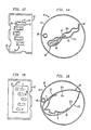
- the other wall member 32 is substantially flat and has lidding area members or closure members which close each of the respective facing member of pockets 34 and releasably adhered to it. Pocket members 34 are superimposed on these closure members in the drawings, see Fig. 17.
- Other areas of wall member 32 each forms an extension member b as in Fig. 15, to each closure member.
- Each closure extension member extends from the edge of each of closure member to the edge of wall member 32.
- Each extension ends at a predetermined distance from the edge of its closure member.
- Each extension is affixed permanently at its end by one of weld portions 35 to a predetermined location or spot on interior wall 27c. These spots on interior wall 27c are on the same locations and are superimposed by weld portions 35 in the drawings. They may be referred to in the drawing by the same numeral 35.
- Each of pocket members 34 is releasably closed by wall member 32 to encapsulate within each of pocket members 34 a predetermined quantity of aliquot of component 36, which may be either in the form of powder or a solution.
- component 37 Disposed within pouch 27 is component 37 including a solvent.
- starting delay means or device 38 which as shown is in the form of dissolvable capsule and contains an inital charge of component 36. Pouch 27 is then closed by sealing its open end. After the elapse of a predetermined period of time after assembling expulsion assembly 20 and disposing it within container 10, filling product 19 therein, and placing tubing 25 and barrier 22 in place and capping container 10 with top 13 and its associated parts, capsule 38 dissolves and causes component 36 contained therein to be exposed and to mix and react with component 37 and generate the initial quantity of pressuirzing gas, thereby inflating and expanding bag or pouch 27 and providing dispensing pressure within container 10.
- the solvent portion of component 37 which is in a liquid state during the useful life of the dispenser may be added in a liquid state or in a frozen state during manufacturing.
- cavities or pocket members 34 and capsule 38 may carry component 36, e.g. citric acid in powder form or in solution, and component 37 may be sodium bicarbonate and water, or the two carbon dioxide gas generating components can be switched the other way around.
- component 36 e.g. citric acid in powder form or in solution
- component 37 may be sodium bicarbonate and water, or the two carbon dioxide gas generating components can be switched the other way around.
- Pouch 27 in one preferred embodiment, is constructed of a three layer laminated film having a middle layer of saran, an external layer of Mylar about 0.5 mils thick, and the inside layer (the interior of the pouch) being low density polyethylene of about 1.5 mils thick, and the saran layer is only deposited from spray.
- the characteristics required or desired in said pouch is that it be non-toxic, has sufficient mechanical strength and chemical stability, and flexible but not appreciably stretchable, and the interior facing surfaces of the pouch be heat sealable.
- Pouch 27 can also be constructed from other films such as impervious or non-impervious, non-laminated or laminated with plastics, foil or treated fabrics or other suitable material which may be available.
- Wall member 32 is fabricated from the same material which contacts the interior of pouch 27 and is of compatible plastic material, e.g. low density polyethylene. In one preferred embodiment, it has an overall thickness of about 4.5 mils and is a three layer sandwich of about 0.5 mils mylar in the middle and about 2.0 mils of low density polyethylene on either sides. Wall member 32 may also be constructed from other films such as impervious or non-impervious, coated or non-coated, laminated with plastics, foil or treated fabrics or any other suitable material which may be available.
- compatible plastic material e.g. low density polyethylene.
- Wall member 32 may also be constructed from other films such as impervious or non-impervious, coated or non-coated, laminated with plastics, foil or treated fabrics or any other suitable material which may be available.
- Wall member 33 carrying the cup-shaped depressions or pocket members 34, adapted for deep drawing and is in one preferred embodiment a laminated plastic sheet having an exterior layer - (the layer in contact with the interior of pouch 27)- of low density polyethylene of about 0.5 mils to about 20 mils thick and an interior layer (the other side) of polypropylene of from about 0.1 mils to about 3.75 mils thick or higher.
- Wall member 33 may also be constructed from any other suitable material.
- components 36 and 37 as citric acid and sodium bicarbonate mixed with water respectively are normally preferred, it is possible that under particular circumstances other materials may be suitable such as, for example, dilute hydrochloric acid (e.g. 10 to 30%) may replace citric acid, and lithium carbonate or calcium carbonate my replace the sodium bicarbonate.
- component 36 may be selected from any suitable material which can react with component 37 and generate a pressurizing gas, and the contents of each of pocket members 34 and capsule 38 may be the same material or different from each other.
- the radio-activity at the surface of the dispenser and its component parts and accessories as well as that of the product discharged therefrom is within human tolerence, an does not exceed 0.1 milliroentgen per hour at the time of manufacturing. This requirement may be obtained by blending materials of lower level radio-activity than the level required with materials of higher level radio-activity than the level required in order to produce blended materials of the required low level radio-activity.
- Capsule 38 which functions as the starting delay means or device, may be constructed from any suitable material, such as gelatin, or coating such as shellac, or any breachable or breakable barrier enclosure.
- the method of assembly requires the following data to be determined:
- capsule 38 disintegrates, its content of component 36 is released and reacts with second component 37 within pouch 27, and generates the initial predetermined quantity of pressure generating gas which raises the internal pressure therein to the predetermined maximum pressure level, and pouch 27 inflates and expands within container 10.
- each quantity of component 36 encapsulated in each of closed pocket members 34 is released sequentially and reacts with component 37 within pouch 27 and generates sequentially additonal predetermined quantities of pressurizing gas therein each time the internal pressure within pouch 27 drops from predetermined maximum pressure level to predetermined minimum pressure level.
- These additional quantities of pressurizing gas raise the internal pressure within pouch 27 from predetermined minimum pressure levels to predetermined maximum pressure levels.
- the increases in the size of pouch 27 cause its facing walls to push outwardly, and thereby the distance between interior wall members 27c and 27d as well as the distances between identifiable spots on these two walls increase.
- each of closed pocket members 34 separate from their respective closure members and said closed pocket members open sequentially and discharge their contents, which react with component 37 and generate sequentially additional predetermined quantities of pressurizing gas, which raise the pressure therein to predetermined maximum levels.
- the internal pressure within pouch 27 alternates between predetermined maximum and minimum pressure levels, until dispensing product 19 is completed.
- the method of assembly is depicted schematically in Figs. 4 to 8 and 9 to 11.
- cavities or pockets are formed on portions of sheet 33, and extension members to each of pockets 34 are formed on other portions of sheet 33.
- Each of these extensions extends from the edge of the opening of each member of pockets 34 and ends at the edge of sheet 33.
- Each extension ends at a predetermined distance from the edge of the opening of its pocket member.
- Predetermined quantities of component 36 e.g. citric acid are deposited in each member of pockets 34.
- Each of these quantities and the length of the extension of each pocket member are predetermined according to the order of the sequential opening of each closed pocket member in the manner to be described.
- sheet 32 is overlayed on sheet 33 and they are releasably sealed together (Fig. 5) to close each of pockets 34, and thereby form enfoldment 31.
- Portions of sheet 32 become liddings or closures to each member of pockets 34.
- Other portions of sheet 32 become extensions to each of these closure members.
- Each extension member extends from the edge of each closure member to the edge of wall member 32.
- Each extension ends at a predetermined distance from the edge of its closure member. The length of the extension of each closure is predetermined according to the order of the sequential opening in the manner to be described.
- Enfoldment 31 is inserted into the open end 30 of pouch 27.
- each extension member of pocket members 34 is affixed permanently to predetermined identified location or spot on interior wall 27d by one of weld portions 35
- the end of each extension member of the closure members is affixed permanently to predetermined identified location or spot on interior wall 27c by one of weld portions 35, (Fig. 8.).
- Capsule 38 and a predetermined quantity of component 37 which includes water which may be in a frozen state are deposited within pouch 27, and then upper edge 30 is closed and heat sealed permanently to completely enclose the contents in pouch 27 and thereby complete the assembly of expulsion means 20.
- This expulsion means assembly 20 is then inserted into container 10 and product 19 is added therein around it, barrier 22 and perforated tubing 25 are put into place, and top 13 is affixed to container (10 Fig.) 10.
- the frozen ingredient in component 37 melts, and capsule 38 has dissolved and generates a predetermined quantity of pressurizing gas, e.g. carbon dioxide gas, which inflates, pressurizes and causes pouch 27 to expand, and the dispenser is now ready for use (Fig. 11.) Figs.
- pressurizing gas e.g. carbon dioxide gas
- FIG. 3 12, and 13 show schematically how interior walls 27c and 27d of pouch 27 are permanently affixed and welded at weld portions 35 to the exterior of wall members 32 and 33, and how the expansion of pouch 27 causes the closure members to separate from their respective pocket members and open and expose their content of first component 36 to admix and react with the second component 37 and water within pouch 27 and thereby generate additional predetermined quantities of the pressurizing gas.
- Enfoldment 31 may also be sliced in suitable patterns to form smaller units of enfoldment 31, each comprised of a single closed pocket member 34 encapsulating a predetermined quantity of component 36.
- Each pocket and its closure has an extension extending to the edges of sheet 33 and 32 respectively as described above.
- Each of single closed pocket members 34 may be disposed within pouch 27 unattached to the other closed pocket members.
- Each extension of pocket members 34 ends at a predetermined distance from the edge of the opening of its respective pocket member, and each extension of the closure members ends at a predetermined distance from the edge of its respective closure member. Each of these ends defines a free end of their respective extensions.
- the delay device may be constructed from gelatinous material in the form of a gelatinous capsule or a pouch which disintegrates in its sourrounding within the expulsion assembly, and it may also be a container or an enclosure constructed from glass or any other suitable material, which is broken open within the expulsion assembly at any time before or after assembling the dispenser, whichever situation is suitable in the manufacturing process.
- the second component of the two-component gas generation system 37 may include an ingredient in a frozen state at the time when it is deposited within pouch 27 and subsequently it liquifies.
- expulsion assembly 20 comprising a bag or pouch 27 enclosing: a gelatin capsule 38 encapsulating a predetermined quantity of citric acid, and a predetermined quantity of sodium bicarbonate and 5 cc of water, and an insignificant quantity of atmospheric air, and having displacement capacity of 12 cc, is disposed within container 10 having displacement capacity of 140 cc.
- a gelatin capsule 38 encapsulating a predetermined quantity of citric acid, and a predetermined quantity of sodium bicarbonate and 5 cc of water, and an insignificant quantity of atmospheric air, and having displacement capacity of 12 cc, is disposed within container 10 having displacement capacity of 140 cc.
- One hundred (100) cc of flowable product 19 is introduced into container 10 around expulsion means 20, and barrier member 22 and perforated tubing 25 are put in place, and top 13 is affixed on container 10 to close it.
- the aggregate head space above the liquid in container 10 and in expulsion assembly 20 is 28 cc, occupied by atmospheric air.
- citric acid is required to completely react with enough quantity of sodium bicarbonate in aqueous medium in order to generate 1 cc of carbon dioxide gas compressed under 144 psig. (pound per square inch gauge), and 0.03458 gms. of sodium bicarbonate is required to completely react with enough quantity of citric acid in aqueous medium in order to generate 1 cc of carbon dioxide gas compressed under 144 psig.
- the internal pressure within the 28 cc of head space in container 10 should measure one atmospheric pressure or 14.4 psig.
- An additional quantity of pressurizing gas is required to provide another 25.2cc of pressurizing gas compressed under 144 psig. for raising the pressure in the total head space of 28cc within container 10 to 144 psig.
- This 25.2cc is the difference between 28 cc and 2.8 cc.
- This quantity of citric acid is encapsulated in capsule 38, which is deposited within pouch 27 together with the sodium bicarbonate and water, which may be in a frozen state. After a predetermined period of time, this capsule disintegrates or dissolves and releases its content within pouch 27. Its 0.665 gms. content of citric acid reacts with the sodium bicarbonate within pouch 27 and generates the required quantity of additional pressurizing gas which raises the pressure within this space of 28 cc to 144 psig.
- This quantity of 0.325 gms of citric acid is encapsulated in one of closed pocket members 34 which is disposed within pouch 27 and is scheduled to open first among the plurality of closed pocket members 34 which are scheduled to open within pouch 27.
- any quantity of citric acid ranging between 0.2 gms. and 0.97 gms. encapsulated within this closed pocket member which is disposed within pouch 27 and is scheduled to open fourth in sequence, will provide pressure within the range between 100 psig. and 144 psig. at the time when discharging product 19 from this dispenser is completed, and thus conform with the requirements specified for this dispenser.
- the four (4) closed pocket members mentioned above are required to be disposed within pouch 27 according to the order of their sequential opening.
- Item d mentioned above may be determined as follows:
- the length of the extension of the pocket member and the length of the extension of its respective closure memer of each of closed pocket members (34) may be determined as follows:
- the internal pressure within pouch 27 is dealt with as synonymous to that of expulsion assembly means 20 and is equivalent to the internal pressure within container 10.
- step XVI is duplicated, and the dispenser is assembled and completed on the production line.
- dispenser of other specifications can be processed as well.
- the pouch will line the interior of the container.
Landscapes
- Chemical & Material Sciences (AREA)
- Chemical Kinetics & Catalysis (AREA)
- Electrochemistry (AREA)
- General Chemical & Material Sciences (AREA)
- Dispersion Chemistry (AREA)
- Engineering & Computer Science (AREA)
- Mechanical Engineering (AREA)
- Containers And Packaging Bodies Having A Special Means To Remove Contents (AREA)
Priority Applications (3)
| Application Number | Priority Date | Filing Date | Title |
|---|---|---|---|
| DE1990105133 DE447579T1 (de) | 1990-03-19 | 1990-03-19 | Regulierter unter druck stehender spender und methode. |
| AT90105133T ATE118437T1 (de) | 1990-03-19 | 1990-03-19 | Füllungsverfahren eines regulierten unter druck stehenden spenders. |
| DE1990617003 DE69017003T2 (de) | 1990-03-19 | 1990-03-19 | Füllungsverfahren eines regulierten unter Druck stehenden Spenders. |
Applications Claiming Priority (2)
| Application Number | Priority Date | Filing Date | Title |
|---|---|---|---|
| US41349882A | 1982-09-02 | 1982-09-02 | |
| US06/671,048 US4646946A (en) | 1982-09-02 | 1984-11-13 | Pressure generating apparatus and method |
Publications (2)
| Publication Number | Publication Date |
|---|---|
| EP0447579A1 true EP0447579A1 (fr) | 1991-09-25 |
| EP0447579B1 EP0447579B1 (fr) | 1995-02-15 |
Family
ID=27022200
Family Applications (1)
| Application Number | Title | Priority Date | Filing Date |
|---|---|---|---|
| EP90105133A Expired - Lifetime EP0447579B1 (fr) | 1982-09-02 | 1990-03-19 | Procédé de remplissage d'un distributeur pressurisé régulé |
Country Status (2)
| Country | Link |
|---|---|
| US (1) | US4646946A (fr) |
| EP (1) | EP0447579B1 (fr) |
Cited By (1)
| Publication number | Priority date | Publication date | Assignee | Title |
|---|---|---|---|---|
| DE10310079A1 (de) * | 2003-03-07 | 2004-09-23 | GMG Beratungs-und Beteiligungs GmbH & Co.KG, | Fluiddispenser und Verfahren zu dessen Betrieb |
Families Citing this family (27)
| Publication number | Priority date | Publication date | Assignee | Title |
|---|---|---|---|---|
| US4646946A (en) * | 1982-09-02 | 1987-03-03 | Reyner Ellis M | Pressure generating apparatus and method |
| US4909420A (en) * | 1982-09-02 | 1990-03-20 | Reyner Ellis M | Regulated pressurized dispenser and method |
| AU607257B2 (en) * | 1987-09-11 | 1991-02-28 | Ccl Industries Inc. | Method for prepressurizing dispensing container and for filling pressurized container with flowable product |
| US4896794A (en) * | 1987-09-11 | 1990-01-30 | Enviro-Spray Systems, Inc. | Method for prepressurizing dispensing container and for filling pressurized container with flowable product |
| FR2630090B1 (fr) * | 1988-04-18 | 1990-10-12 | Carnaud Sa | Procede de fabrication d'un emballage pour produit pressurise, par exemple un produit a pulveriser et emballage ainsi obtenu |
| US5060823A (en) * | 1988-09-15 | 1991-10-29 | Brandeis University | Sterile transfer system |
| US4919310A (en) * | 1989-03-02 | 1990-04-24 | Adolph Coors Company | Pressure generation system for a container |
| DE3914517A1 (de) * | 1989-03-10 | 1990-09-13 | Coster Tecnologie Speciali Spa | Zweikammerpackung |
| US5137186A (en) * | 1990-01-26 | 1992-08-11 | Ccl Industries Inc. | Method and apparatus for dispensing product from a product bag |
| US5040704A (en) * | 1990-01-26 | 1991-08-20 | Ccl Industries, Inc. | Method and apparatus for dispensing product from a product bag |
| RU2016820C1 (ru) * | 1991-06-29 | 1994-07-30 | Анатолий Яковлевич Столяревский | Способ создания избыточного давления газообразного диоксида углерода внутри рабочего объема упаковки для распыления вещества |
| US5571261A (en) * | 1993-08-06 | 1996-11-05 | River Medical, Inc | Liquid delivery device |
| US5578005A (en) * | 1993-08-06 | 1996-11-26 | River Medical, Inc. | Apparatus and methods for multiple fluid infusion |
| US5397303A (en) * | 1993-08-06 | 1995-03-14 | River Medical, Inc. | Liquid delivery device having a vial attachment or adapter incorporated therein |
| US5398850A (en) * | 1993-08-06 | 1995-03-21 | River Medical, Inc. | Gas delivery apparatus for infusion |
| US5398851A (en) * | 1993-08-06 | 1995-03-21 | River Medical, Inc. | Liquid delivery device |
| IT1272761B (it) * | 1993-10-29 | 1997-06-26 | Claudio Bna | Distributore di pasta dentifricia da un contenitore a pressione, con erogatore a bocca rettangolare |
| US5766147A (en) * | 1995-06-07 | 1998-06-16 | Winfield Medical | Vial adaptor for a liquid delivery device |
| US5700245A (en) * | 1995-07-13 | 1997-12-23 | Winfield Medical | Apparatus for the generation of gas pressure for controlled fluid delivery |
| US5915595A (en) * | 1996-08-21 | 1999-06-29 | U.S. Can Company | Aerosol dispensing container and method for assembling same |
| US5992700A (en) * | 1997-05-28 | 1999-11-30 | Apex Medical Technologies, Inc. | Controlled gas generation for gas-driven infusion devices |
| FR2783513B1 (fr) * | 1998-09-23 | 2000-12-08 | Techniplast | Pulverisateur a generation de gaz propulseur integree |
| EP1026220A1 (fr) * | 1999-02-02 | 2000-08-09 | GOLDWELL GmbH | Procédé pour la production d'une composition d'aérosol |
| AUPS023702A0 (en) * | 2002-01-31 | 2002-02-21 | Fraser-Easton, Gilbert | Pressure regulating device for a pressurised dispensing vessel |
| EP1871689A4 (fr) * | 2005-04-08 | 2008-10-15 | Multi Vet Ltd | Diffuseur d'aerosol a effet venturi utilisant un agent propulseur a base de reactif |
| DE102006009262B4 (de) * | 2006-02-28 | 2008-01-24 | Rolf Vaitl | Selbstaufblasender Regenschirm |
| EP2803631A1 (fr) * | 2013-05-16 | 2014-11-19 | Carlsberg Breweries A/S | Système et procédé de distribution de boisson |
Citations (2)
| Publication number | Priority date | Publication date | Assignee | Title |
|---|---|---|---|---|
| US4646946A (en) * | 1982-09-02 | 1987-03-03 | Reyner Ellis M | Pressure generating apparatus and method |
| US4909420A (en) * | 1982-09-02 | 1990-03-20 | Reyner Ellis M | Regulated pressurized dispenser and method |
Family Cites Families (4)
| Publication number | Priority date | Publication date | Assignee | Title |
|---|---|---|---|---|
| FR1205297A (fr) * | 1957-04-02 | 1960-02-02 | Bradley Container Corp | Procédé de remplissage de récipients à parois déformables |
| US4360131A (en) * | 1979-12-19 | 1982-11-23 | Enviro-Spray Systems, Inc. | Pressure generating apparatus |
| US4376500A (en) * | 1980-07-25 | 1983-03-15 | Enviro-Spray Systems, Inc. | Expandable bag |
| US4373341A (en) * | 1980-12-18 | 1983-02-15 | Mahaffy & Harder Engineering Co. | Expandible package for dispensing containers |
-
1984
- 1984-11-13 US US06/671,048 patent/US4646946A/en not_active Expired - Fee Related
-
1990
- 1990-03-19 EP EP90105133A patent/EP0447579B1/fr not_active Expired - Lifetime
Patent Citations (2)
| Publication number | Priority date | Publication date | Assignee | Title |
|---|---|---|---|---|
| US4646946A (en) * | 1982-09-02 | 1987-03-03 | Reyner Ellis M | Pressure generating apparatus and method |
| US4909420A (en) * | 1982-09-02 | 1990-03-20 | Reyner Ellis M | Regulated pressurized dispenser and method |
Cited By (1)
| Publication number | Priority date | Publication date | Assignee | Title |
|---|---|---|---|---|
| DE10310079A1 (de) * | 2003-03-07 | 2004-09-23 | GMG Beratungs-und Beteiligungs GmbH & Co.KG, | Fluiddispenser und Verfahren zu dessen Betrieb |
Also Published As
| Publication number | Publication date |
|---|---|
| US4646946A (en) | 1987-03-03 |
| EP0447579B1 (fr) | 1995-02-15 |
Similar Documents
| Publication | Publication Date | Title |
|---|---|---|
| EP0447579A1 (fr) | Procédé de remplissage d'un distributeur pressurisé régulé | |
| US4360131A (en) | Pressure generating apparatus | |
| US4376500A (en) | Expandable bag | |
| US5022564A (en) | Regulated pressurized dispenser and method | |
| US3718236A (en) | Pressurized container with non-rigid follower | |
| US3178075A (en) | Pressurized container | |
| US4491250A (en) | Pressurized dispensing pouch | |
| US4909420A (en) | Regulated pressurized dispenser and method | |
| EP0171556B1 (fr) | Poche gonflable | |
| EP0033377B1 (fr) | Récipient comprenant des moyens générateurs de pression | |
| EP0091306B1 (fr) | Système de distribution et pochette de remplissage | |
| US4510734A (en) | Expandable bag and method of manufacture | |
| US3705667A (en) | Proportioning valve for a pressurized dispenser | |
| US3255924A (en) | Pressurized dispensing device | |
| US4896794A (en) | Method for prepressurizing dispensing container and for filling pressurized container with flowable product | |
| GB2240077A (en) | Inflatable enclosure and means to inflate the same. | |
| US5263519A (en) | Ready to fill pressurized dispenser and method | |
| US5040704A (en) | Method and apparatus for dispensing product from a product bag | |
| US3834589A (en) | Pressure-responsive safety device for aerosol dispenser and containers equipped therewith | |
| US4553685A (en) | Dispensing system and a refill pouch | |
| US3738540A (en) | Container for corrosive products to be stored under pressure | |
| US4621483A (en) | Inflatable pouch and method of manufacture | |
| CA2012366C (fr) | Appareil de distribution a pression regulee et methode connexe | |
| JPH03275480A (ja) | 調整加圧ディスペンサ及び方法 | |
| AU616877B2 (en) | Self-generating pressure applying means for a disposable container |
Legal Events
| Date | Code | Title | Description |
|---|---|---|---|
| PUAI | Public reference made under article 153(3) epc to a published international application that has entered the european phase |
Free format text: ORIGINAL CODE: 0009012 |
|
| AK | Designated contracting states |
Kind code of ref document: A1 Designated state(s): AT BE CH DE DK ES FR GB GR IT LI LU NL SE |
|
| TCAT | At: translation of patent claims filed | ||
| EL | Fr: translation of claims filed | ||
| DET | De: translation of patent claims | ||
| 17P | Request for examination filed |
Effective date: 19920227 |
|
| 17Q | First examination report despatched |
Effective date: 19920519 |
|
| GRAA | (expected) grant |
Free format text: ORIGINAL CODE: 0009210 |
|
| AK | Designated contracting states |
Kind code of ref document: B1 Designated state(s): AT BE CH DE DK ES FR GB GR IT LI LU NL SE |
|
| PG25 | Lapsed in a contracting state [announced via postgrant information from national office to epo] |
Ref country code: IT Free format text: LAPSE BECAUSE OF FAILURE TO SUBMIT A TRANSLATION OF THE DESCRIPTION OR TO PAY THE FEE WITHIN THE PRE;WARNING: LAPSES OF ITALIAN PATENTS WITH EFFECTIVE DATE BEFORE 2007 MAY HAVE OCCURRED AT ANY TIME BEFORE 2007. THE CORRECT EFFECTIVE DATE MAY BE DIFFERENT FROM THE ONE RECORDED.SCRIBED TIME-LIMIT Effective date: 19950215 Ref country code: AT Effective date: 19950215 Ref country code: ES Free format text: THE PATENT HAS BEEN ANNULLED BY A DECISION OF A NATIONAL AUTHORITY Effective date: 19950215 Ref country code: DK Effective date: 19950215 Ref country code: GR Free format text: LAPSE BECAUSE OF FAILURE TO SUBMIT A TRANSLATION OF THE DESCRIPTION OR TO PAY THE FEE WITHIN THE PRESCRIBED TIME-LIMIT Effective date: 19950215 Ref country code: NL Effective date: 19950215 |
|
| REF | Corresponds to: |
Ref document number: 118437 Country of ref document: AT Date of ref document: 19950315 Kind code of ref document: T |
|
| REF | Corresponds to: |
Ref document number: 69017003 Country of ref document: DE Date of ref document: 19950323 |
|
| ET | Fr: translation filed | ||
| PGFP | Annual fee paid to national office [announced via postgrant information from national office to epo] |
Ref country code: CH Payment date: 19950418 Year of fee payment: 6 |
|
| PG25 | Lapsed in a contracting state [announced via postgrant information from national office to epo] |
Ref country code: SE Effective date: 19950515 |
|
| NLV1 | Nl: lapsed or annulled due to failure to fulfill the requirements of art. 29p and 29m of the patents act | ||
| PLBE | No opposition filed within time limit |
Free format text: ORIGINAL CODE: 0009261 |
|
| STAA | Information on the status of an ep patent application or granted ep patent |
Free format text: STATUS: NO OPPOSITION FILED WITHIN TIME LIMIT |
|
| 26N | No opposition filed | ||
| PG25 | Lapsed in a contracting state [announced via postgrant information from national office to epo] |
Ref country code: LI Effective date: 19960331 Ref country code: CH Effective date: 19960331 |
|
| REG | Reference to a national code |
Ref country code: CH Ref legal event code: PL |
|
| PGFP | Annual fee paid to national office [announced via postgrant information from national office to epo] |
Ref country code: LU Payment date: 20000404 Year of fee payment: 11 |
|
| PG25 | Lapsed in a contracting state [announced via postgrant information from national office to epo] |
Ref country code: LU Free format text: LAPSE BECAUSE OF NON-PAYMENT OF DUE FEES Effective date: 20010319 |
|
| PGFP | Annual fee paid to national office [announced via postgrant information from national office to epo] |
Ref country code: GB Payment date: 20010627 Year of fee payment: 12 Ref country code: FR Payment date: 20010627 Year of fee payment: 12 |
|
| PGFP | Annual fee paid to national office [announced via postgrant information from national office to epo] |
Ref country code: DE Payment date: 20010702 Year of fee payment: 12 |
|
| PGFP | Annual fee paid to national office [announced via postgrant information from national office to epo] |
Ref country code: BE Payment date: 20010716 Year of fee payment: 12 |
|
| REG | Reference to a national code |
Ref country code: GB Ref legal event code: IF02 |
|
| PG25 | Lapsed in a contracting state [announced via postgrant information from national office to epo] |
Ref country code: GB Free format text: LAPSE BECAUSE OF NON-PAYMENT OF DUE FEES Effective date: 20020319 |
|
| PG25 | Lapsed in a contracting state [announced via postgrant information from national office to epo] |
Ref country code: BE Free format text: LAPSE BECAUSE OF NON-PAYMENT OF DUE FEES Effective date: 20020331 |
|
| BERE | Be: lapsed |
Owner name: *JOY RESEARCH INC. Effective date: 20020331 |
|
| PG25 | Lapsed in a contracting state [announced via postgrant information from national office to epo] |
Ref country code: DE Free format text: LAPSE BECAUSE OF NON-PAYMENT OF DUE FEES Effective date: 20021001 |
|
| GBPC | Gb: european patent ceased through non-payment of renewal fee |
Effective date: 20020319 |
|
| PG25 | Lapsed in a contracting state [announced via postgrant information from national office to epo] |
Ref country code: FR Free format text: LAPSE BECAUSE OF NON-PAYMENT OF DUE FEES Effective date: 20021129 |
|
| REG | Reference to a national code |
Ref country code: FR Ref legal event code: ST |