EP0447607A2 - Hermetische Anschlussklemme für Endpolaranordnung mit schmelzbarer Verbindung, verwendet für eine Motorkompressoreinheit - Google Patents
Hermetische Anschlussklemme für Endpolaranordnung mit schmelzbarer Verbindung, verwendet für eine Motorkompressoreinheit Download PDFInfo
- Publication number
- EP0447607A2 EP0447607A2 EP90116526A EP90116526A EP0447607A2 EP 0447607 A2 EP0447607 A2 EP 0447607A2 EP 90116526 A EP90116526 A EP 90116526A EP 90116526 A EP90116526 A EP 90116526A EP 0447607 A2 EP0447607 A2 EP 0447607A2
- Authority
- EP
- European Patent Office
- Prior art keywords
- pin
- segment
- pin segment
- compressor unit
- disposed
- Prior art date
- Legal status (The legal status is an assumption and is not a legal conclusion. Google has not performed a legal analysis and makes no representation as to the accuracy of the status listed.)
- Withdrawn
Links
Images


Classifications
-
- H—ELECTRICITY
- H01—ELECTRIC ELEMENTS
- H01R—ELECTRICALLY-CONDUCTIVE CONNECTIONS; STRUCTURAL ASSOCIATIONS OF A PLURALITY OF MUTUALLY-INSULATED ELECTRICAL CONNECTING ELEMENTS; COUPLING DEVICES; CURRENT COLLECTORS
- H01R13/00—Details of coupling devices of the kinds covered by groups H01R12/70 or H01R24/00 - H01R33/00
- H01R13/73—Means for mounting coupling parts to apparatus or structures, e.g. to a wall
- H01R13/74—Means for mounting coupling parts in openings of a panel
-
- H—ELECTRICITY
- H01—ELECTRIC ELEMENTS
- H01R—ELECTRICALLY-CONDUCTIVE CONNECTIONS; STRUCTURAL ASSOCIATIONS OF A PLURALITY OF MUTUALLY-INSULATED ELECTRICAL CONNECTING ELEMENTS; COUPLING DEVICES; CURRENT COLLECTORS
- H01R2201/00—Connectors or connections adapted for particular applications
- H01R2201/10—Connectors or connections adapted for particular applications for dynamoelectric machines
-
- Y—GENERAL TAGGING OF NEW TECHNOLOGICAL DEVELOPMENTS; GENERAL TAGGING OF CROSS-SECTIONAL TECHNOLOGIES SPANNING OVER SEVERAL SECTIONS OF THE IPC; TECHNICAL SUBJECTS COVERED BY FORMER USPC CROSS-REFERENCE ART COLLECTIONS [XRACs] AND DIGESTS
- Y10—TECHNICAL SUBJECTS COVERED BY FORMER USPC
- Y10S—TECHNICAL SUBJECTS COVERED BY FORMER USPC CROSS-REFERENCE ART COLLECTIONS [XRACs] AND DIGESTS
- Y10S417/00—Pumps
- Y10S417/902—Hermetically sealed motor pump unit
-
- Y—GENERAL TAGGING OF NEW TECHNOLOGICAL DEVELOPMENTS; GENERAL TAGGING OF CROSS-SECTIONAL TECHNOLOGIES SPANNING OVER SEVERAL SECTIONS OF THE IPC; TECHNICAL SUBJECTS COVERED BY FORMER USPC CROSS-REFERENCE ART COLLECTIONS [XRACs] AND DIGESTS
- Y10—TECHNICAL SUBJECTS COVERED BY FORMER USPC
- Y10S—TECHNICAL SUBJECTS COVERED BY FORMER USPC CROSS-REFERENCE ART COLLECTIONS [XRACs] AND DIGESTS
- Y10S439/00—Electrical connectors
- Y10S439/926—Electrical connectors within machine casing or motor housing, connector within casing wall
Definitions
- the present invention relates generally to hermetic compressors of the type having a hermetic housing, wherein a hermetic terminal is provided for carrying electric current into the housing and, more particularly, to such a terminal that will maintain the integrity of its hermetic seal even under overcurrent conditions.
- a hermetic terminal is installed in a hole formed in the housing of a hermetic compressor so that current may be carried to the compressor motor from an external source of power.
- the terminal comprises a body member welded or otherwise secured to the compressor outer housing and a plurality of conductor pins extending through the body member.
- a glass-to-metal seal is employed, having an epoxy and/or silicon rubber overcoating. Both the inner and outer ends of the conductive pins may be provided with conductor tabs so as to facilitate connection to the external current source and to the compressor motor.
- a problem associated with prior art hermetic terminals is that, in response to unexpected abnormally high overcurrent conditions, e.g., due to a ground fault or a short circuit, the conductor pins may heat up to the point of melting the conductor pins themselves or the surrounding glass-to-metal seals, thereby resulting in failure of the hermetic terminal.
- One method for preventing occurrence of the aforementioned failure mode of a hermetic terminal is to use a fusible link within the conductive path of each conductor pin.
- the fusible link portion has a smaller cross-sectional area than the remaining portions of the conductor pin, and is designed to fuse first upon the occurrence of an overcurrent condition.
- the fusible link will fuse and terminate the supply of electric current to the compressor motor before the conductor and/or glass-to-metal seal are destroyed by excessive temperatures.
- a pin assembly in one prior art hermetic terminal, includes a fusible link attached to and disposed intermediate two pin parts. Specifically, opposite axial ends of the fusible link are received in respective axial bores in the ends of the pin parts. The ends are then crimped to create electrical contact between the pin parts and the fusible link. It is generally recognized that a crimped attachment provides a high resistance and unreliable electrical connection.
- some terminal assemblies do not provide a reservoir into which a melted or vaporized fusible link may migrate in the event of an overcurrent condition. Such assemblies risk the possibility of incomplete electrical separation between the pin parts and the fusible link.
- a hermetic terminal includes pin assemblies each having a fuse link surrounded by a multi-piece protective capsule defining an expansion cavity.
- the protective capsule In order to exhaust the built-up pressure in the capsule and, at the same time, maintain the integrity of the seal between the conductor pin assemblies and body member of the hermetic terminal, the protective capsule is designed to rupture upon rapid vaporization of the fuse material within the expansion cavity. In such an assembly, an outer sealing member fractures upon rupture of the protective capsule, thereby causing the pin parts to separate from the remainder of the terminal.
- a disadvantage of this hermetic terminal design is the existence of many component parts, including the requirement of a fracturing sealing member surrounding the protective capsule on an extended inner or outer side of the terminal body.
- the present invention provides a hermetic terminal including fusible terminal pin assemblies extending through apertures in the terminal body, wherein each terminal pin assembly includes an electrically insulating intermediate portion in which is disposed a fusible link that interconnects electrically conducting ends of the pin assembly.
- the intermediate portion of each pin assembly is at least partially disposed within a respective collar portion of the terminal body defining the respective apertures therein.
- a seal is disposed intermediate each pin assembly and a corresponding collar portion of the terminal body.
- the invention provides in one form thereof a hermetic terminal for a hermetic compressor in which two pin segments of a terminal pin assembly are linked together by a fusible material.
- the fusible material and adjacent ends of each segment of the terminal pin assembly are telescopingly received within an electrically insulating protective sleeve.
- the sleeve is disposed at least partially within the collar portion of the hermetic terminal, and provides a cavity for molten fusible material to migrate, thereby ensuring complete electrical disconnection of the pin segments.
- opposite ends of the fusible link are received within respective counterbores in the axial ends of the pin segments and are secured thereto by a brazing material disposed between the fusible link and the counterbore.
- hermetic terminal of the present invention is the provision of fusible terminal pin assemblies of a relatively simple design utilizing a minimum number of component parts.
- hermetic terminal according to the present invention is that a more reliable and better performing connection is provided between pin segments and the fusible link in a conducting pin assembly of the hermetic terminal, whereby the connection results in lower pin segment temperatures when an electrical current is passed therethrough.
- a further advantage of the hermetic terminal of the present invention is that an expansion cavity is provided for the fusible link without requiring a molded sealing member surrounding the structure defining the expansion cavity.
- Still another advantage of the hermetic terminal of the present invention in one form thereof, is that one pin-to-sleeve joint of each conducting pin assembly is exposed externally of the hermetic terminal and the other pin-to-sleeve joint is sealed within the sealing material closing the respective terminal body aperture, whereby the exposed joint is not subject to compression glass-to-metal seal constraint and, therefore, can be designed to fail upon occurrence of an overcurrent condition, thereby providing an indication of a melted fuse link while maintaining the hermetic seal of the compressor housing.
- the invention in one form thereof, provides a hermetic compressor including a housing having an opening therein.
- An electric motor is operatively disposed within the housing.
- the compressor also includes a hermetic terminal for carrying electric current from an external source of power to the motor within the housing.
- the hermetic terminal comprises a metallic body member closing the housing opening, and a plurality of collar portions defining pin openings in the body member.
- a plurality of current-conducting pin assemblies are disposed in the pin openings and pass through the body member.
- Each pin assembly includes an inner pin segment disposed at least partially inside the housing, an electrically insulating intermediate pin segment, and an outer pin segment disposed at least partially outside the housing, wherein the intermediate segment interconnects the inner and outer segments.
- the intermediate pin segment is a sleeve disposed at least partially within the collar portion, wherein the inner and outer pin segments are telescopingly received within opposite ends of the sleeve.
- the intermediate pin segment defines a closed cavity with the inner and outer pin segments, and a fusible link is provided within the closed cavity for fusibly and electrically interconnecting the inner pin segment and the outer pin segment.
- a glass seal is disposed intermediate each pin assembly and its corresponding collar portion to seal each of the openings in the body member.
- the invention further provides, in one form thereof, a compressor having a hermetic terminal comprising a body member and a current conducting pin assembly passing through the body member.
- the pin assembly comprises a first pin segment, a second pin segment and an electrically insulating sleeve interconnecting the first pin segment and the second pin segment.
- the sleeve defines a closed cavity with the first and second pin segments.
- a fusible link having opposite ends is disposed within the cavity.
- the first and second pin segments are connected to opposite ends of the fusible link by first and second brazed joints, respectively.
- Another object of the present invention is to provide a hermetic terminal assembly having a fusible link that cuts off the flow of current but does not necessitate rupture of other terminal components in the event of an overcurrent condition.
- Still another object of the present invention in one form thereof, is to provide a hermetic terminal in which melting of the fusible link is readily detected upon sight.
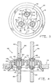
- a hermetic compressor 10 having a housing generally designated at 12.
- Housing 12 comprises a top portion 14, a central portion 16, and a lower portion (not shown).
- the three housing portions are hermetically sealed together as by welding or brazing.
- Disposed within housing 12 is an electric motor generally designated at 18.
- Motor 18 comprises a stator 20 having windings 22, and a rotor 24 having an end cap 26 to which a counterweight 28 is attached.
- the stator is secured to housing 12 by an interference fit such as by shrink fitting.
- Rotor 24 has a central aperture 30 provided therein into which is secured a rotatable crankshaft 32 by an interference fit.
- Crankshaft 32 is drivingly connected to a compressor mechanism (not shown), e.g., a reciprocating compressor or rotary vane compressor, which compresses refrigerant for discharge into the interior of housing 12.
- a refrigerant discharge tube 34 extends through top portion 14 of the housing and has an end 36 thereof extending into the interior of the compressor housing as shown. The tube is sealingly connected to housing 12 at 38, as by soldering.
- Top portion 14 includes an opening 40 in which is provided a hermetic terminal assembly 42 for carrying electrical current from outside of housing 12 to motor 18 when compressor 10 is operably connected to an external power source (not shown).
- An electric plug and wiring assembly 44 connects to terminal assembly 42 on the interior of the housing and carries current to stator windings 22.
- Compressor 10 also includes a post 46 welded to top portion 14 for mounting a terminal cover (not shown) to cover terminal assembly 42 once compressor 10 is operably installed.
- terminal assembly 42 comprises a metallic, cup-shaped body member 48 having a flange 50 and three inwardly extending collars 52 defining respective openings 54 extending through body member 48.
- Flange 50 is disposed against the inner surface 49 of cover 14 of housing 12 when terminal assembly 42 is welded into place, thereby ensuring that the body member 48 will not be dislodged by the high pressure within housing 12.
- a metallic conductor pin assembly 56 is received and retained in each of the openings 54.
- Each conducting pin assembly 56 comprises a first pin segment 60 extending externally of housing 12, a second pin segment 62 disposed substantially within housing 12, and a fusible link 64 having opposite ends 61 and 63 connected to first and second segments 60 and 62, respectively.
- end 61 is received within a counterbore 65 in pin segment 60 and is brazed therein using a brazing filler metal, e.g., a silver-based alloy.
- end 63 is received and brazed within a counterbore 66 in pin segment 62.
- the ends of fusible link 64 may abut with and be brazed to first and second segments 60 and 62 without counterbores. It is contemplated that the connections between fusible link 64 and first and second segments 60 and 62 may also be made by welding, e.g., laser welding.
- pin segments 60 and 62 are 446 stainless steel or some other suitable electrically conducting materials, such as copper cored 446 stainless steel.
- pin assemblies 56 are optionally provided with tabs 58 secured to their external ends to facilitate the attachment of connecting leads (not shown).
- fusible link 64 is cylindrical in shape, having a diameter of approximately 0.040 inch, and is composed of a phosphor bronze material having a melting temperature in the range of approximately 1750 to 1970 degrees Fahrenheit.
- fusible link 64 may be composed of other materials and/or assume other configurations and sizes in order to achieve the desired overcurrent limit or temperature, or to facilitate welding or brazing thereof.
- An insulating sleeve 68 preferably made of an electrically insulating ceramic material, e.g., alumina, is axially interposed between pin segments 60 and 62 and coaxially surrounds fusible link 64 to form an expansion cavity 70 circumjacent fusible link 64.
- pin segments 60 and 62 are each telescopingly received into opposite open ends of sleeve 68.
- pin segments 60 and 62 are sealingly retained within the open ends of sleeve 68 at brazed or glass-to-metal seal joints 72 and 73, respectively.
- a brazed joint requires that the connecting portion of the ceramic sleeve first be metalized.
- each pin assembly 56 In order to electrically insulate each pin assembly 56 from body member 48 and to seal the annular space between each pin assembly and the inner surfaces 74 of a respective collar 52, the annular space is filled with a glass seal 76, which is compression fused therein.
- seal 76 contacts sleeve 68 and surrounds the junction between pin segment 62 and sleeve 68, thereby providing a compression glass-to-metal seal constraint thereabout.
- the junction between pin segment 60 and sleeve 68 remains exposed on the exterior of the compressor housing and is not subject to a compression glass-to-metal seal constraint.
- a compression glass-to-metal seal constraint is not provided at the junction between pin segment 60 and sleeve 68 in the embodiment of Figs. 2 and 3 can be used to optionally design a pin assembly in which an intentional separation of that junction occurs, thereby providing a visual indication that an overcurrent condition has occurred.
- an overcurrent condition occurs and fuse link 64 melts or vaporizes, an increased pressure is developed in expansion cavity 70.
- the unconstrained junction between pin segment 60 and sleeve 68 can be designed to respond to the increased pressure by cracking or separating to provide a visual indication.
- Figs. 4 and 5 show hermetic terminals applicable to the compressor of Fig. 1 in accordance with alternative embodiments of the present invention, wherein the aforementioned description of the embodiment of Figs. 2 and 3 is equally applicable with the following exceptions.
- seal 176 contacts sleeve 168 and surrounds the junction between pin segment 160 and sleeve 168, while the junction between pin segment 162 and sleeve 168 remains exposed on the interior of the compressor housing.
- the axial dimension of sleeve 268 is increased, whereby the respective junctions between sleeve 268 and pin segments 260 and 262 are not surrounded by seal 276. Instead, seal 276 contacts only sleeve 268.
- the axial extent to which pin segments 260 and 262 are telescopingly received within sleeve 268 is greater than that of the other embodiments, thereby providing more contacting and bonding surface area for joints 272 and 273.
- hermetic terminals of the type disclosed herein, it is recognized that it is desirable to maintain "flat" glass-to-metal seals between conductor pins and their respective collar portions of the terminal body, i.e., the integrity of the seal is enhanced with the compression glass-to-metal seal constraint provided by this arrangement.
- the glass-to-metal seal has been made to climb the conductor pin axially away from the collar portions. Under certain circumstances, this puts the unconstrained portion of the glass seal in tension, resulting in cracking or the like.
- insulating sleeve 268 is interposed in the radial space between pin segments 260 and 262 and collar 252, while the diameter of the pin segments and the radial thickness of glass seal 276 are maintained substantially at standard dimensions. Accordingly, the diameter of collars 252 is increased to accommodate the insulating sleeve 268 of the present invention. Consequently, as illustrated in Fig. 5, greater oversurface and through-seal insulating distances are achieved using a "flatter" glass-to-metal seal, which seal exhibits compression glass-to-metal seal constraint along the entire axial length thereof.
- the inside diameter of collar 254 is approximately 0.300 inch and the outside diameter of sleeve 268 is approximately 0.200 inch, thereby resulting in a uniform radial thickness for glass seal 276 of approximately .050 inch.
- the inside diameter of sleeve 268, according to this particular embodiment, is approximately 0.135 inch.
- connection between fusible link 64 and pin segments 60 and 62 may be made by brazing.
- pin assembly 56 is assembled by first brazing the fusible link and pin segments together, and then sliding insulating sleeve 68 into position and making the brazed or glass-to-metal seal joints 72 and 73, it is recommended that a eutectic braze alloy be used to braze the fusible link and pin segments in order to avoid reflow when subsequently making joints 72 and 73.
Landscapes
- Compressor (AREA)
- Connections Arranged To Contact A Plurality Of Conductors (AREA)
- Motor Or Generator Frames (AREA)
- Connection Of Motors, Electrical Generators, Mechanical Devices, And The Like (AREA)
Applications Claiming Priority (2)
| Application Number | Priority Date | Filing Date | Title |
|---|---|---|---|
| US07/497,086 US4964788A (en) | 1990-03-21 | 1990-03-21 | Hermetic terminal with terminal pin assemblies having fusible links and motor compressor unit including same |
| US497086 | 1990-03-21 |
Publications (2)
| Publication Number | Publication Date |
|---|---|
| EP0447607A2 true EP0447607A2 (de) | 1991-09-25 |
| EP0447607A3 EP0447607A3 (en) | 1992-09-02 |
Family
ID=23975401
Family Applications (1)
| Application Number | Title | Priority Date | Filing Date |
|---|---|---|---|
| EP19900116526 Withdrawn EP0447607A3 (en) | 1990-03-21 | 1990-08-29 | Hermetic terminal with terminal pin assemblies having fusible links and motor compressor unit including same |
Country Status (5)
| Country | Link |
|---|---|
| US (1) | US4964788A (de) |
| EP (1) | EP0447607A3 (de) |
| JP (1) | JPH0612940B2 (de) |
| BR (1) | BR9004622A (de) |
| CA (1) | CA2023760C (de) |
Cited By (7)
| Publication number | Priority date | Publication date | Assignee | Title |
|---|---|---|---|---|
| EP0685856A3 (de) * | 1994-05-31 | 1996-09-11 | Emerson Electric Co | Isolationsanordnung für ein geschweisstes hermetisches Endstück. |
| DE10018974C2 (de) * | 1999-04-30 | 2002-08-14 | Yazaki Corp | Anschlussklemme und Schalter |
| EP1045504A3 (de) * | 1999-04-12 | 2003-10-29 | Matsushita Electric Industrial Co., Ltd. | Motorgetriebene Kompressoreinheit |
| CN101986519A (zh) * | 2010-06-30 | 2011-03-16 | 苏州贝得科技有限公司 | 封闭式制冷压缩机用电动机接线端子 |
| EP2672117A1 (de) * | 2012-06-08 | 2013-12-11 | Kabushiki Kaisha Toyota Jidoshokki | Motorbetriebener Verdichter |
| WO2016097903A1 (en) | 2014-12-19 | 2016-06-23 | Szikra Istvan | Electric connector device primarily for the hermetically sealed compressor of refrigerators |
| EP3322038A4 (de) * | 2015-07-06 | 2019-02-20 | Schott Japan Corporation | Luftdichter abschluss mit sicherung |
Families Citing this family (41)
| Publication number | Priority date | Publication date | Assignee | Title |
|---|---|---|---|---|
| DE4021411C2 (de) * | 1990-07-06 | 1993-09-30 | Oplaender Wilo Werk Gmbh | Anschlußstecker für Doppel-Kreiselpumpe |
| US5192194A (en) * | 1991-04-23 | 1993-03-09 | Air Engineers, Inc. | Explosion proof compressor and a method for explosion proofing a compressor |
| CA2158232C (fr) † | 1994-09-14 | 2001-08-07 | Marcel-Claude Braud | Chariot de manutention motorise a bras telescopique |
| JPH116479A (ja) * | 1997-06-18 | 1999-01-12 | Matsushita Electric Ind Co Ltd | 密閉型圧縮機 |
| US6315528B1 (en) * | 1999-05-27 | 2001-11-13 | Scroll Technologies | Terminal connection in small area of scroll compressor and method for carrying out same |
| US6375497B1 (en) | 1999-12-17 | 2002-04-23 | Tecumseh Products Company | Recessed hermetic terminal assembly |
| US6273754B1 (en) * | 2000-04-13 | 2001-08-14 | Tecumseh Products Company | Protective covering for the terminal assembly of a hermetic compressor assembly |
| US6555754B2 (en) * | 2001-01-18 | 2003-04-29 | Walbro Corporation | Automotive fuel tank electrical fitting |
| DE60228680D1 (de) * | 2002-02-27 | 2008-10-16 | Pfaudler Werke Gmbh | Verfahren zur Herstellung einer elektrisch leitenden Verbindung zwischen Metallkomponenten, die mit nichtleitenden Material beschichtet sind |
| US6844502B2 (en) * | 2002-05-16 | 2005-01-18 | Emerson Electric Co. | Hermetically sealed current conducting terminal assembly |
| US6870098B2 (en) * | 2002-09-23 | 2005-03-22 | Tecumseh Products Company | Conduit-ready terminal cover |
| CA2440255A1 (en) * | 2003-09-09 | 2005-03-09 | Fuelmaker Corporation | Gas compressor with drier and radio emission controls |
| JP2005207328A (ja) * | 2004-01-23 | 2005-08-04 | Toyota Industries Corp | 圧縮機 |
| US20060140791A1 (en) * | 2004-12-29 | 2006-06-29 | Deming Glenn I | Miniature rotary compressor, and methods related thereto |
| WO2007005981A1 (en) * | 2005-07-05 | 2007-01-11 | Emerson Electric Co. | Electric power terminal feed-through |
| DE102007031727A1 (de) * | 2006-08-31 | 2008-03-20 | Zf Friedrichshafen Ag | Verbindungselement zum Verbinden von elektrischen Leitern |
| US8262372B2 (en) | 2007-05-10 | 2012-09-11 | Emerson Climate Technologies, Inc. | Compressor hermetic terminal |
| US8939734B2 (en) * | 2007-08-28 | 2015-01-27 | Emerson Climate Technologies, Inc. | Molded plug for a compressor |
| US8939735B2 (en) * | 2009-03-27 | 2015-01-27 | Emerson Climate Technologies, Inc. | Compressor plug assembly |
| EP2290750B1 (de) * | 2009-08-31 | 2015-10-07 | Pfaudler Werke GmbH | Elektrischer Anschluss zwischen elektrisch leitfähigen Elementen |
| JP5267601B2 (ja) | 2011-03-08 | 2013-08-21 | 株式会社豊田自動織機 | 電動圧縮機 |
| JP5252006B2 (ja) | 2011-03-08 | 2013-07-31 | 株式会社豊田自動織機 | 電動圧縮機 |
| JP2012228974A (ja) * | 2011-04-27 | 2012-11-22 | Toyota Motor Corp | 動力装置 |
| US9484732B2 (en) | 2011-12-14 | 2016-11-01 | Johnson Controls Technology Company | Method and apparatus for sealing motor terminals |
| JP5609900B2 (ja) * | 2012-02-02 | 2014-10-22 | 株式会社豊田自動織機 | 電動圧縮機 |
| JP5720593B2 (ja) * | 2012-02-02 | 2015-05-20 | 株式会社豊田自動織機 | 電動圧縮機 |
| US9874213B2 (en) * | 2012-05-25 | 2018-01-23 | Andrey Yurievich Yazykov | Centrifugal multiple-impeller electric pump |
| US9480177B2 (en) | 2012-07-27 | 2016-10-25 | Emerson Climate Technologies, Inc. | Compressor protection module |
| US8851923B2 (en) * | 2012-08-08 | 2014-10-07 | Emerson Electric Co. | Hermetically sealed terminal pins with holes for connecting to wires |
| WO2016157236A1 (ja) * | 2015-03-27 | 2016-10-06 | 三菱電機株式会社 | 流体機械 |
| CN110541819B (zh) * | 2018-05-28 | 2020-11-20 | 杭州三花研究院有限公司 | 电子油泵 |
| CN110541818B (zh) * | 2018-05-28 | 2020-11-20 | 杭州三花研究院有限公司 | 电子油泵 |
| JP6960377B2 (ja) * | 2018-06-07 | 2021-11-05 | 東芝三菱電機産業システム株式会社 | 電気機械内蔵耐圧装置および電力供給部通過構造処理方法 |
| JP7132120B2 (ja) * | 2018-12-28 | 2022-09-06 | ショット日本株式会社 | 気密端子 |
| CN110729578B (zh) * | 2019-10-12 | 2025-06-24 | 珠海凌达压缩机有限公司 | 一种接线柱结构及包括该接线柱结构的电器 |
| EP3936722B1 (de) * | 2020-07-06 | 2024-09-04 | Schott Ag | Gehäuseteil, im speziellen ein gehäuseteil insbesondere für ein elektronisches gehäuse, vorzugsweise ein e-kompressoranschluss |
| DE102020122910A1 (de) * | 2020-09-02 | 2022-03-03 | Schott Ag | Durchführung |
| CN112382871A (zh) * | 2020-10-22 | 2021-02-19 | 青岛万宝压缩机有限公司 | 一种双重防护的密封接线装置及压缩机 |
| CN218351760U (zh) * | 2022-07-07 | 2023-01-20 | 艾默生电气(铜陵)有限公司 | 密封式端子组件 |
| EP4428368B1 (de) * | 2023-03-07 | 2025-01-15 | Schott Ag | Elektrische durchführungsanordnung |
| EP4704258A1 (de) * | 2024-09-03 | 2026-03-04 | Schott Ag | Elektrische durchführungsanordnung |
Family Cites Families (10)
| Publication number | Priority date | Publication date | Assignee | Title |
|---|---|---|---|---|
| US2700085A (en) * | 1953-07-30 | 1955-01-18 | Westinghouse Air Brake Co | Electrical fuse device |
| US3007130A (en) * | 1956-08-13 | 1961-10-31 | Technology Instr Corp Of Acton | Hermetically sealed electrical connector |
| US3988053A (en) * | 1975-01-20 | 1976-10-26 | Dodenhoff John A | Hermetic terminal |
| US4252394A (en) * | 1979-05-16 | 1981-02-24 | Tecumseh Products Company | Hermetic compressor motor terminal |
| US4480151A (en) * | 1982-07-19 | 1984-10-30 | Hilliard Dozier | Temperature stable hermetically sealed terminal |
| US4584433A (en) * | 1984-12-03 | 1986-04-22 | Emerson Electric Co. | Hermetic terminal assembly |
| US4609774A (en) * | 1985-06-18 | 1986-09-02 | B & W Electronic Enclosures, Inc. | Electrical terminal construction with fusible section |
| US4739551A (en) * | 1986-07-14 | 1988-04-26 | Emerson Electric Co. | Hermetic terminal assembly pin and method and apparatus for making the same |
| US4786762A (en) * | 1988-03-03 | 1988-11-22 | Emerson Electric Co. | Sleeve arrangement for a hermetic terminal assembly |
| US4830630A (en) * | 1988-08-22 | 1989-05-16 | Hilliard Dozier | Hermetically sealed electrical terminal |
-
1990
- 1990-03-21 US US07/497,086 patent/US4964788A/en not_active Expired - Fee Related
- 1990-08-22 CA CA002023760A patent/CA2023760C/en not_active Expired - Fee Related
- 1990-08-29 EP EP19900116526 patent/EP0447607A3/en not_active Withdrawn
- 1990-08-30 JP JP2230453A patent/JPH0612940B2/ja not_active Expired - Lifetime
- 1990-09-17 BR BR909004622A patent/BR9004622A/pt not_active IP Right Cessation
Cited By (9)
| Publication number | Priority date | Publication date | Assignee | Title |
|---|---|---|---|---|
| EP0685856A3 (de) * | 1994-05-31 | 1996-09-11 | Emerson Electric Co | Isolationsanordnung für ein geschweisstes hermetisches Endstück. |
| EP1045504A3 (de) * | 1999-04-12 | 2003-10-29 | Matsushita Electric Industrial Co., Ltd. | Motorgetriebene Kompressoreinheit |
| DE10018974C2 (de) * | 1999-04-30 | 2002-08-14 | Yazaki Corp | Anschlussklemme und Schalter |
| CN101986519A (zh) * | 2010-06-30 | 2011-03-16 | 苏州贝得科技有限公司 | 封闭式制冷压缩机用电动机接线端子 |
| EP2672117A1 (de) * | 2012-06-08 | 2013-12-11 | Kabushiki Kaisha Toyota Jidoshokki | Motorbetriebener Verdichter |
| US9267502B2 (en) | 2012-06-08 | 2016-02-23 | Kabushiki Kaisha Toyota Jidoshokki | Motor-driven compressor |
| WO2016097903A1 (en) | 2014-12-19 | 2016-06-23 | Szikra Istvan | Electric connector device primarily for the hermetically sealed compressor of refrigerators |
| EP3322038A4 (de) * | 2015-07-06 | 2019-02-20 | Schott Japan Corporation | Luftdichter abschluss mit sicherung |
| US10340642B2 (en) | 2015-07-06 | 2019-07-02 | Schott Japan Corporation | Fuse-equipped hermetic terminal |
Also Published As
| Publication number | Publication date |
|---|---|
| BR9004622A (pt) | 1991-11-19 |
| US4964788A (en) | 1990-10-23 |
| JPH0612940B2 (ja) | 1994-02-16 |
| EP0447607A3 (en) | 1992-09-02 |
| CA2023760C (en) | 1993-08-31 |
| JPH03273844A (ja) | 1991-12-05 |
| CA2023760A1 (en) | 1991-09-22 |
Similar Documents
| Publication | Publication Date | Title |
|---|---|---|
| US4964788A (en) | Hermetic terminal with terminal pin assemblies having fusible links and motor compressor unit including same | |
| US4252394A (en) | Hermetic compressor motor terminal | |
| CA1090434A (en) | Fused oil filled capacitor | |
| US4532489A (en) | Fuses, particularly subminiature cartridge fuses, and a method of manufacture thereof | |
| US6094128A (en) | Overload protected solid state varistors | |
| CA2100016C (en) | Electrical heater with a contamination-proof seal | |
| US4646053A (en) | Electric fuse having welded fusible elements | |
| CN100492574C (zh) | 温度熔断器和使用它的电池 | |
| US20020101323A1 (en) | High-voltage current-limiting fuse | |
| US4616155A (en) | Overvoltage discharger for coaxial cables and method of making same | |
| US4609774A (en) | Electrical terminal construction with fusible section | |
| US4921452A (en) | Breakaway hermetically sealed electrical terminal | |
| CA1081295A (en) | Modular type fuse assembly | |
| US4830630A (en) | Hermetically sealed electrical terminal | |
| EP3322038B1 (de) | Luftdichter abschluss mit sicherung | |
| JP2005158352A (ja) | ヒューズ付き電線 | |
| US4628294A (en) | End cap assembly for a fluid resistant electrical device | |
| JP4036630B2 (ja) | ヒューズおよびヒューズの製造方法 | |
| US6995332B2 (en) | Resistance welding method and structure of resistance welding part, and method for manufacturing electronic component and electronic component | |
| TW202333178A (zh) | 電熔斷器 | |
| US4401963A (en) | Resistor insertion fuse | |
| CA2472829C (en) | Fuse with metallic state indicator | |
| KR20220009201A (ko) | 고전압 퓨즈 | |
| JPS6314357Y2 (de) | ||
| JPS5936831Y2 (ja) | 電線ヒユ−ズ |
Legal Events
| Date | Code | Title | Description |
|---|---|---|---|
| PUAI | Public reference made under article 153(3) epc to a published international application that has entered the european phase |
Free format text: ORIGINAL CODE: 0009012 |
|
| AK | Designated contracting states |
Kind code of ref document: A2 Designated state(s): DE FR IT |
|
| PUAL | Search report despatched |
Free format text: ORIGINAL CODE: 0009013 |
|
| AK | Designated contracting states |
Kind code of ref document: A3 Designated state(s): DE FR IT |
|
| STAA | Information on the status of an ep patent application or granted ep patent |
Free format text: STATUS: THE APPLICATION IS DEEMED TO BE WITHDRAWN |
|
| 18D | Application deemed to be withdrawn |
Effective date: 19930303 |