EP0447620A1 - Machine de forage à avance automatique - Google Patents
Machine de forage à avance automatique Download PDFInfo
- Publication number
- EP0447620A1 EP0447620A1 EP90121456A EP90121456A EP0447620A1 EP 0447620 A1 EP0447620 A1 EP 0447620A1 EP 90121456 A EP90121456 A EP 90121456A EP 90121456 A EP90121456 A EP 90121456A EP 0447620 A1 EP0447620 A1 EP 0447620A1
- Authority
- EP
- European Patent Office
- Prior art keywords
- drilling
- spindle axis
- drilling machine
- support
- workpiece
- Prior art date
- Legal status (The legal status is an assumption and is not a legal conclusion. Google has not performed a legal analysis and makes no representation as to the accuracy of the status listed.)
- Granted
Links
- 238000005553 drilling Methods 0.000 title claims abstract description 85
- 238000000034 method Methods 0.000 claims description 6
- 238000004873 anchoring Methods 0.000 claims description 4
- 230000002093 peripheral effect Effects 0.000 abstract 1
- 238000010276 construction Methods 0.000 description 2
- 230000000694 effects Effects 0.000 description 1
- 238000012986 modification Methods 0.000 description 1
- 230000004048 modification Effects 0.000 description 1
Images
Classifications
-
- B—PERFORMING OPERATIONS; TRANSPORTING
- B23—MACHINE TOOLS; METAL-WORKING NOT OTHERWISE PROVIDED FOR
- B23B—TURNING; BORING
- B23B47/00—Constructional features of components specially designed for boring or drilling machines; Accessories therefor
- B23B47/28—Drill jigs for workpieces
-
- B—PERFORMING OPERATIONS; TRANSPORTING
- B23—MACHINE TOOLS; METAL-WORKING NOT OTHERWISE PROVIDED FOR
- B23Q—DETAILS, COMPONENTS, OR ACCESSORIES FOR MACHINE TOOLS, e.g. ARRANGEMENTS FOR COPYING OR CONTROLLING; MACHINE TOOLS IN GENERAL CHARACTERISED BY THE CONSTRUCTION OF PARTICULAR DETAILS OR COMPONENTS; COMBINATIONS OR ASSOCIATIONS OF METAL-WORKING MACHINES, NOT DIRECTED TO A PARTICULAR RESULT
- B23Q35/00—Control systems or devices for copying directly from a pattern or a master model; Devices for use in copying manually
- B23Q35/02—Copying discrete points from the pattern, e.g. for determining the position of holes to be drilled
-
- B—PERFORMING OPERATIONS; TRANSPORTING
- B23—MACHINE TOOLS; METAL-WORKING NOT OTHERWISE PROVIDED FOR
- B23Q—DETAILS, COMPONENTS, OR ACCESSORIES FOR MACHINE TOOLS, e.g. ARRANGEMENTS FOR COPYING OR CONTROLLING; MACHINE TOOLS IN GENERAL CHARACTERISED BY THE CONSTRUCTION OF PARTICULAR DETAILS OR COMPONENTS; COMBINATIONS OR ASSOCIATIONS OF METAL-WORKING MACHINES, NOT DIRECTED TO A PARTICULAR RESULT
- B23Q9/00—Arrangements for supporting or guiding portable metal-working machines or apparatus
- B23Q9/0014—Portable machines provided with or cooperating with guide means supported directly by the workpiece during action
Definitions
- the invention relates to a drilling machine with automatic feed for producing rows of holes in workpieces with a uniformly curved surface, according to the preamble of patent claim 1.
- Known drilling machines of this type such as those used for the production of rows of rivet holes on circular-cylindrical fuselage parts, have a guide foot which can be placed on the workpiece surface by means of adjustable support elements and is displaceable on the machine housing in the axial direction of the drilling spindle, and a guide foot which can be adjusted radially to the drilling spindle axis in accordance with the respective borehole distance Guide slot in the guide foot in the previous drill hole insertable pin, with the help of the drill for the purpose of automatic feed on the workpiece in the correct position, namely with the drilling spindle axis perpendicular to the local tangential plane at the respective drilling point, is clamped on one side from the workpiece surface without any clamping elements that must be positioned on the back of the workpiece.
- the drilling machine according to the invention can be displaced on the curved workpiece surface in any desired direction in such a way that both the dowel pin can be positioned above or in a preceding borehole, and an angularly accurate, preferably vertical alignment the drilling spindle axis to the local tangential plane of the workpiece surface is ensured at the respective drilling point.
- oval or other, arbitrary borehole patterns can be drilled on a uniformly curved workpiece, such as a partially cylindrical aircraft fuselage part, with extremely little work and construction effort and without cumbersome readjustment of the support elements, all bores with the exception of the first one in the borehole row with automatic feed and a secure fixation of the drilling machine to the workpiece can be carried out for the duration of the drilling process.
- the drilling machine is expediently perpendicular to the local one with the drilling spindle axis Tangential plane of the workpiece surface clamped, ie the borehole axes of the individual boreholes each run in the direction of the local surface normal.
- the support device and the dowel pin are arranged independently of one another concentrically to the drilling spindle axis in a plane perpendicular to this to pivot.
- the recess in the support device provides an adjustment possibility of the dowel pin that is sufficient for most borehole images and is nevertheless kept as small as possible for reasons of stability, it is expediently designed according to claim 3 as a circular ring sector concentric to the spindle axis.
- the cutout can of course also have a geometrically different shape in individual cases.
- a particularly tilt-resistant support and torque-safe anchoring of the drilling machine housing during the drilling process is preferably achieved according to claim 4 in that the support device is provided with a recess provided with the support plate, which is rotatably mounted about the drilling spindle axis, and a surface lying on the supporting plate and together with the drilling machine housing concentrically with the drilling spindle axis contains a guide foot that can be rotated relative to the support plate and has a radial guide slot for the dowel pin.
- the support elements form at least one four-point support on the workpiece surface, so that it can be determined by simply checking the stability of the support device on the workpiece surface whether the support device is in contact with the workpiece at all four support points has and is therefore in the correct orientation to the workpiece surface for an angular fixation of the drilling spindle axis with respect to the local surface normal.
- a particularly simple possibility of adjusting the support elements to the radius of curvature of simply curved workpieces is achieved in that the support elements remote from the drill spindle are attached to the support device as an angle bar which can be placed in rectilinear contact on a support line of the workpiece surface and is adjustable in relation to the distance from the drill spindle axis are trained.
- one of the support elements is advisable to design one of the support elements as a fixed point in the form of a support ring arranged coaxially with the drill spindle axis and provided with a through hole for the drilling tool, as a result of which improved support is achieved directly in the edge region of the drilling point and, when using a drilling template, the exact positioning of the Drill is made easier with the help of the support ring.
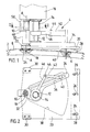
- the drilling machine shown in the Fig. Is used for drilling a uniformly circular cylindrical workpiece 2 with automatic feed and is fastened on one side to the workpiece 2 by means of a clamping and supporting device 4 in such a way that the drilling spindle axis AA perpendicular to the local tangential plane at the respective one during the drilling process Drilling site remains held.
- the individual drilling positions on the workpiece 2 are defined by a drilling template 8 which conforms to the workpiece surface and is provided with through holes 6 in accordance with the desired hole pattern.
- the tensioning and supporting device 4 contains three guide sleeves 10, 12 and 14, by means of which the housing 16 of the drilling machine is supported on the device 4 so as to be vertically displaceable.
- the guide sleeve 10 is arranged coaxially to the drilling spindle (not shown) and the drilling tool 18 attached to it and encircling it in a ring, while the other two guide sleeves 12 and 14 run in a concentric arrangement with a parallel distance to the drilling spindle axis AA, and the guide sleeve 14 with respect to the sleeve 12 is axially displaceable and rotatable.
- a support plate 20 is pivotally mounted relative to the housing 16 about the drill spindle axis AA by means of a bearing bush 22, such that the drill spindle axis A is perpendicular to the plate plane is held.
- a support element 24 in the form of an annular collar provided with a through opening for the drilling tool 18, which rests on the workpiece surface at the respective drilling point and positions the drilling spindle axis A concentrically with the corresponding through hole 6 of the drilling template 8.
- the support plate 20 is mounted on the support plate 20 via additional support elements, namely an angle bar 28, which is adjustably fastened to the support plate 20 via slot connections 26 with respect to the distance to the drill spindle axis A and is preset in accordance with the workpiece curvature, and two support pieces 30 arranged on the corners of the support plate 20 on the drill spindle side Positioned workpiece surface or the drilling template 8 that the drilling spindle axis A lies exactly at the local surface normal at each drilling point, the support elements 24 and 30 on the one hand and the angle bar 28 on the other hand each along a surface line of the cylinder surface with the workpiece 2 or the drilling template 8 in Are in contact.
- the support plate 20 has only a two-point support on the workpiece (or drilling template) surface, so that checking the stability of the support plate 20 provides a simple means of checking and correcting the Correct positioning of the support plate 20 offers.
- the tensioning and supporting device 4 also has a guide foot 34 attached to the guide sleeve 12 and - by means of a bush-shaped extension piece 32 - to the guide sleeve 10, which is pressed by the guide sleeve 12 into surface contact with the upper side of the support plate 20 and with respect to the Drilling spindle axis A radial guide slot 36 is provided.
- a circular sector-shaped recess 38 which lies within the contact area of the support plate 20 delimited by the support elements 24, 28 and 30 and whose radial length and angular size are dimensioned such that with proper alignment of the support plate 20 on the work support surface at least one at every new drilling position the preceding borehole lies below the recess 38, so that then by rotating the machine housing 16 and the guide foot 34, which is coupled non-rotatably with it via the guide sleeves 10 and 12, the guide slot 36 is positioned above the preceding borehole with respect to the support plate 20 and a dowel pin slidably displaceable in the guide slot 36 40 can be inserted into the borehole.
- the dowel pin 40 is connected via a cantilever arm 42 and a pivot pin 44 to a lever-shaped extension 46 of the guide sleeve 14, which is displaceably and rotatably mounted on the sleeve 12, and when the drill is actuated, a feed cylinder (not shown) arranged in the machine housing is activated by the the sleeve 14 is drawn into the machine housing 16. Under the effect of the tensile force exerted on the dowel pin 40, it first spreads in the preceding borehole, whereupon the machine housing 16 and thus also the drilling spindle and the drilling tool 18 attached to it are shifted in the correct position towards the workpiece 2 on the guide sleeves 10, 12.
- an adjustable contact lever 50 on the machine housing 16 is actuated by a stop 48 fastened to the extension piece 32 of the guide foot 34 and the feed cylinder is thereby released, so that the tension pin 40, which is now relieved of tensile force, is released from the bore and the machine housing 16 on the guide sleeves 10 , 12 is raised and the spindle drive is switched off, whereupon the drilling process can be repeated at a further drilling point.
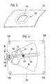
- FIG. 3 An oval drill hole pattern 52 that can be produced with the described drilling machine for a recessed row of rivet holes in the region of the window cutout 54 of a part-cylindrical aircraft fuselage part 56 is shown in FIG. 3.
- This modification of the support elements makes the drilling machine usable not only for circularly curved, but also for workpieces with a two-dimensionally curved, spherical workpiece surface, the height-adjustable support elements 128, 130 in turn being preset in accordance with the surface curvature so that all support elements including the plate-fixed support ring 24 rest on the workpiece or - when using a drilling template - on the template surface and hold the support plate plane parallel to the local tangential plane of the workpiece on the drilling spindle axis A.
- the construction and operation of the drilling machine according to FIG. 4 is the same as in the first exemplary embodiment.
Landscapes
- Engineering & Computer Science (AREA)
- Mechanical Engineering (AREA)
- Automation & Control Theory (AREA)
- Drilling And Boring (AREA)
- Processing Of Stones Or Stones Resemblance Materials (AREA)
Applications Claiming Priority (2)
| Application Number | Priority Date | Filing Date | Title |
|---|---|---|---|
| DE4005431A DE4005431A1 (de) | 1990-02-21 | 1990-02-21 | Bohrmaschine mit automatischem vorschub |
| DE4005431 | 1990-02-21 |
Publications (2)
| Publication Number | Publication Date |
|---|---|
| EP0447620A1 true EP0447620A1 (fr) | 1991-09-25 |
| EP0447620B1 EP0447620B1 (fr) | 1994-03-09 |
Family
ID=6400647
Family Applications (1)
| Application Number | Title | Priority Date | Filing Date |
|---|---|---|---|
| EP90121456A Expired - Lifetime EP0447620B1 (fr) | 1990-02-21 | 1990-11-09 | Machine de forage à avance automatique |
Country Status (2)
| Country | Link |
|---|---|
| EP (1) | EP0447620B1 (fr) |
| DE (2) | DE4005431A1 (fr) |
Cited By (4)
| Publication number | Priority date | Publication date | Assignee | Title |
|---|---|---|---|---|
| WO2002102535A1 (fr) * | 2001-06-18 | 2002-12-27 | Novator Ab | Dispositif de fixation pour une unite de percage orbital portative |
| US20140147222A1 (en) * | 2011-05-23 | 2014-05-29 | Messier-Bugatti-Dowty | Portable equipment for machining a lower portion of an aircraft landing gear casing |
| CN105182799A (zh) * | 2015-09-24 | 2015-12-23 | 成都飞机工业(集团)有限责任公司 | 一种飞机薄壁曲面蒙皮自动钻铆的编程方法 |
| CN117817000A (zh) * | 2023-12-10 | 2024-04-05 | 哈尔滨学院 | 一种钢琴金属踏板钻床装置 |
Families Citing this family (2)
| Publication number | Priority date | Publication date | Assignee | Title |
|---|---|---|---|---|
| CN114131288B (zh) * | 2021-11-08 | 2023-10-20 | 陕西飞机工业有限责任公司 | 一种用于控制叉耳结构同轴度、垂直度的制孔方法 |
| CN114473730B (zh) * | 2022-01-17 | 2023-05-09 | 清华大学 | 用于夹持带沟槽零部件的夹具组件及夹持方法 |
Citations (4)
| Publication number | Priority date | Publication date | Assignee | Title |
|---|---|---|---|---|
| US2674906A (en) * | 1950-08-31 | 1954-04-13 | Robert F Krainz | Hole spacing attachment for drill presses |
| WO1985003466A1 (fr) * | 1984-02-13 | 1985-08-15 | The Boeing Company | Perceuse traversante automatique et son procede d'utilisation |
| DE3516782A1 (de) * | 1984-08-31 | 1986-03-06 | Hermann Telfs Tirol Ganner | Einrichtung zur herstellung von lochreihen bei moebelbauelementen |
| US4850763A (en) * | 1988-10-03 | 1989-07-25 | The Boeing Company | Tool track for use on aircraft |
Family Cites Families (3)
| Publication number | Priority date | Publication date | Assignee | Title |
|---|---|---|---|---|
| US2963927A (en) * | 1959-10-26 | 1960-12-13 | Boeing Co | Self aligning drill motor clamp |
| US4310269A (en) * | 1980-02-19 | 1982-01-12 | Northrop Corporation | Drill break-through sensor |
| GB2103126A (en) * | 1981-08-05 | 1983-02-16 | British Aerospace | Machining tool, e.g. drill, positioning devices |
-
1990
- 1990-02-21 DE DE4005431A patent/DE4005431A1/de active Granted
- 1990-11-09 EP EP90121456A patent/EP0447620B1/fr not_active Expired - Lifetime
- 1990-11-09 DE DE90121456T patent/DE59004934D1/de not_active Expired - Fee Related
Patent Citations (4)
| Publication number | Priority date | Publication date | Assignee | Title |
|---|---|---|---|---|
| US2674906A (en) * | 1950-08-31 | 1954-04-13 | Robert F Krainz | Hole spacing attachment for drill presses |
| WO1985003466A1 (fr) * | 1984-02-13 | 1985-08-15 | The Boeing Company | Perceuse traversante automatique et son procede d'utilisation |
| DE3516782A1 (de) * | 1984-08-31 | 1986-03-06 | Hermann Telfs Tirol Ganner | Einrichtung zur herstellung von lochreihen bei moebelbauelementen |
| US4850763A (en) * | 1988-10-03 | 1989-07-25 | The Boeing Company | Tool track for use on aircraft |
Cited By (5)
| Publication number | Priority date | Publication date | Assignee | Title |
|---|---|---|---|---|
| WO2002102535A1 (fr) * | 2001-06-18 | 2002-12-27 | Novator Ab | Dispositif de fixation pour une unite de percage orbital portative |
| US20140147222A1 (en) * | 2011-05-23 | 2014-05-29 | Messier-Bugatti-Dowty | Portable equipment for machining a lower portion of an aircraft landing gear casing |
| CN105182799A (zh) * | 2015-09-24 | 2015-12-23 | 成都飞机工业(集团)有限责任公司 | 一种飞机薄壁曲面蒙皮自动钻铆的编程方法 |
| CN117817000A (zh) * | 2023-12-10 | 2024-04-05 | 哈尔滨学院 | 一种钢琴金属踏板钻床装置 |
| CN117817000B (zh) * | 2023-12-10 | 2024-07-30 | 哈尔滨学院 | 一种钢琴金属踏板钻床装置 |
Also Published As
| Publication number | Publication date |
|---|---|
| EP0447620B1 (fr) | 1994-03-09 |
| DE4005431A1 (de) | 1991-08-29 |
| DE59004934D1 (de) | 1994-04-14 |
| DE4005431C2 (fr) | 1993-09-09 |
Similar Documents
| Publication | Publication Date | Title |
|---|---|---|
| EP0233370B1 (fr) | Dispositif de réglage pour éléments de travail adjoints aux rouleaux des machines à carder le coton ou la laine | |
| DE2735073C2 (fr) | ||
| EP0447620B1 (fr) | Machine de forage à avance automatique | |
| DE3736757C1 (de) | Tischfraeseinrichtung | |
| EP0430228A2 (fr) | Machine à percer | |
| EP0118077B1 (fr) | Butée à onglets | |
| DE19716631C2 (de) | Einrichtung zum Toleranzausgleich für eine Schneideinrichtung | |
| DE2248827C2 (de) | Nadelstangenführung einer Nähmaschine | |
| DE2323737C3 (de) | Vorrichtung zum Gravieren rotationssymmetrischer Werkstücke | |
| DE2315724C3 (fr) | ||
| WO2000041461A2 (fr) | Tamiseur oscillant | |
| DE3433658C2 (fr) | ||
| EP0413203A2 (fr) | Dispositif de perçage | |
| DE2315724B2 (de) | Vorrichtung zur abstuetzung von werkstuecken bzw. werkzeugen | |
| DE29506683U1 (de) | Schlüsselkopierfräsmaschine und Zylinderflachschlüssel | |
| DE3305210A1 (de) | Handbohrgeraet mit einer bohrlehre zum setzen von duebelloechern | |
| DE2059558C3 (de) | Verstellbarer Endanschlag | |
| DE10101185B4 (de) | Spulvorrichtung für eine Kreuzspulen herstellende Textilmaschine | |
| DE8505686U1 (de) | Schneideinrichtung für Kettensägen | |
| CH612870A5 (en) | Machine for grinding drills | |
| DE29810061U1 (de) | Vorrichtung zum Temperieren von Vorformlingen | |
| DE1602955C3 (de) | Vorrichtung zum automatischen Bohren von Entladeöffnungen beliebiger Anordnung im Kopf eines DüsenkopfrohHngs | |
| DE171008C (fr) | ||
| DE4039345A1 (de) | Bohrmaschine zur herstellung von gleichen lochabstand aufweisenden lochreihen in werkstuecken | |
| LU88631A1 (de) | Werkzeugstaender |
Legal Events
| Date | Code | Title | Description |
|---|---|---|---|
| PUAI | Public reference made under article 153(3) epc to a published international application that has entered the european phase |
Free format text: ORIGINAL CODE: 0009012 |
|
| 17P | Request for examination filed |
Effective date: 19910801 |
|
| AK | Designated contracting states |
Kind code of ref document: A1 Designated state(s): DE FR GB IT NL |
|
| RAP1 | Party data changed (applicant data changed or rights of an application transferred) |
Owner name: EUROCOPTER DEUTSCHLAND GESELLSCHAFT MIT BESCHRAENK |
|
| 17Q | First examination report despatched |
Effective date: 19930709 |
|
| GRAA | (expected) grant |
Free format text: ORIGINAL CODE: 0009210 |
|
| AK | Designated contracting states |
Kind code of ref document: B1 Designated state(s): DE FR GB IT NL |
|
| REF | Corresponds to: |
Ref document number: 59004934 Country of ref document: DE Date of ref document: 19940414 |
|
| GBT | Gb: translation of ep patent filed (gb section 77(6)(a)/1977) |
Effective date: 19940330 |
|
| ITF | It: translation for a ep patent filed | ||
| ET | Fr: translation filed | ||
| PLBE | No opposition filed within time limit |
Free format text: ORIGINAL CODE: 0009261 |
|
| STAA | Information on the status of an ep patent application or granted ep patent |
Free format text: STATUS: NO OPPOSITION FILED WITHIN TIME LIMIT |
|
| 26N | No opposition filed | ||
| PGFP | Annual fee paid to national office [announced via postgrant information from national office to epo] |
Ref country code: GB Payment date: 19991027 Year of fee payment: 10 |
|
| PGFP | Annual fee paid to national office [announced via postgrant information from national office to epo] |
Ref country code: FR Payment date: 19991123 Year of fee payment: 10 |
|
| PGFP | Annual fee paid to national office [announced via postgrant information from national office to epo] |
Ref country code: NL Payment date: 19991130 Year of fee payment: 10 |
|
| PGFP | Annual fee paid to national office [announced via postgrant information from national office to epo] |
Ref country code: DE Payment date: 20000320 Year of fee payment: 10 |
|
| PG25 | Lapsed in a contracting state [announced via postgrant information from national office to epo] |
Ref country code: GB Free format text: LAPSE BECAUSE OF NON-PAYMENT OF DUE FEES Effective date: 20001109 |
|
| PG25 | Lapsed in a contracting state [announced via postgrant information from national office to epo] |
Ref country code: NL Free format text: LAPSE BECAUSE OF NON-PAYMENT OF DUE FEES Effective date: 20010601 |
|
| GBPC | Gb: european patent ceased through non-payment of renewal fee |
Effective date: 20001109 |
|
| PG25 | Lapsed in a contracting state [announced via postgrant information from national office to epo] |
Ref country code: FR Free format text: LAPSE BECAUSE OF NON-PAYMENT OF DUE FEES Effective date: 20010731 |
|
| NLV4 | Nl: lapsed or anulled due to non-payment of the annual fee |
Effective date: 20010601 |
|
| PG25 | Lapsed in a contracting state [announced via postgrant information from national office to epo] |
Ref country code: DE Free format text: LAPSE BECAUSE OF NON-PAYMENT OF DUE FEES Effective date: 20010801 |
|
| REG | Reference to a national code |
Ref country code: FR Ref legal event code: ST |
|
| PG25 | Lapsed in a contracting state [announced via postgrant information from national office to epo] |
Ref country code: IT Free format text: LAPSE BECAUSE OF NON-PAYMENT OF DUE FEES;WARNING: LAPSES OF ITALIAN PATENTS WITH EFFECTIVE DATE BEFORE 2007 MAY HAVE OCCURRED AT ANY TIME BEFORE 2007. THE CORRECT EFFECTIVE DATE MAY BE DIFFERENT FROM THE ONE RECORDED. Effective date: 20051109 |