EP0536532A2 - Machine à percer, notamment pour le travail du bois - Google Patents
Machine à percer, notamment pour le travail du bois Download PDFInfo
- Publication number
- EP0536532A2 EP0536532A2 EP92115039A EP92115039A EP0536532A2 EP 0536532 A2 EP0536532 A2 EP 0536532A2 EP 92115039 A EP92115039 A EP 92115039A EP 92115039 A EP92115039 A EP 92115039A EP 0536532 A2 EP0536532 A2 EP 0536532A2
- Authority
- EP
- European Patent Office
- Prior art keywords
- drilling
- drilling unit
- fingers
- finger
- holding
- Prior art date
- Legal status (The legal status is an assumption and is not a legal conclusion. Google has not performed a legal analysis and makes no representation as to the accuracy of the status listed.)
- Withdrawn
Links
Images


Classifications
-
- B—PERFORMING OPERATIONS; TRANSPORTING
- B27—WORKING OR PRESERVING WOOD OR SIMILAR MATERIAL; NAILING OR STAPLING MACHINES IN GENERAL
- B27C—PLANING, DRILLING, MILLING, TURNING OR UNIVERSAL MACHINES FOR WOOD OR SIMILAR MATERIAL
- B27C3/00—Drilling machines or drilling devices; Equipment therefor
-
- B—PERFORMING OPERATIONS; TRANSPORTING
- B23—MACHINE TOOLS; METAL-WORKING NOT OTHERWISE PROVIDED FOR
- B23Q—DETAILS, COMPONENTS, OR ACCESSORIES FOR MACHINE TOOLS, e.g. ARRANGEMENTS FOR COPYING OR CONTROLLING; MACHINE TOOLS IN GENERAL CHARACTERISED BY THE CONSTRUCTION OF PARTICULAR DETAILS OR COMPONENTS; COMBINATIONS OR ASSOCIATIONS OF METAL-WORKING MACHINES, NOT DIRECTED TO A PARTICULAR RESULT
- B23Q16/00—Equipment for precise positioning of tool or work into particular locations not otherwise provided for
- B23Q16/006—Equipment for precise positioning of tool or work into particular locations not otherwise provided for positioning by bringing a stop into contact with one of two or more stops, fitted on a common carrier
-
- Y—GENERAL TAGGING OF NEW TECHNOLOGICAL DEVELOPMENTS; GENERAL TAGGING OF CROSS-SECTIONAL TECHNOLOGIES SPANNING OVER SEVERAL SECTIONS OF THE IPC; TECHNICAL SUBJECTS COVERED BY FORMER USPC CROSS-REFERENCE ART COLLECTIONS [XRACs] AND DIGESTS
- Y10—TECHNICAL SUBJECTS COVERED BY FORMER USPC
- Y10T—TECHNICAL SUBJECTS COVERED BY FORMER US CLASSIFICATION
- Y10T408/00—Cutting by use of rotating axially moving tool
- Y10T408/36—Machine including plural tools
- Y10T408/37—Turret of tools
-
- Y—GENERAL TAGGING OF NEW TECHNOLOGICAL DEVELOPMENTS; GENERAL TAGGING OF CROSS-SECTIONAL TECHNOLOGIES SPANNING OVER SEVERAL SECTIONS OF THE IPC; TECHNICAL SUBJECTS COVERED BY FORMER USPC CROSS-REFERENCE ART COLLECTIONS [XRACs] AND DIGESTS
- Y10—TECHNICAL SUBJECTS COVERED BY FORMER USPC
- Y10T—TECHNICAL SUBJECTS COVERED BY FORMER US CLASSIFICATION
- Y10T408/00—Cutting by use of rotating axially moving tool
- Y10T408/36—Machine including plural tools
- Y10T408/38—Plural, simultaneously operational tools
- Y10T408/3844—Plural, simultaneously operational tools with tool-opposing, work-engaging surface
-
- Y—GENERAL TAGGING OF NEW TECHNOLOGICAL DEVELOPMENTS; GENERAL TAGGING OF CROSS-SECTIONAL TECHNOLOGIES SPANNING OVER SEVERAL SECTIONS OF THE IPC; TECHNICAL SUBJECTS COVERED BY FORMER USPC CROSS-REFERENCE ART COLLECTIONS [XRACs] AND DIGESTS
- Y10—TECHNICAL SUBJECTS COVERED BY FORMER USPC
- Y10T—TECHNICAL SUBJECTS COVERED BY FORMER US CLASSIFICATION
- Y10T408/00—Cutting by use of rotating axially moving tool
- Y10T408/55—Cutting by use of rotating axially moving tool with work-engaging structure other than Tool or tool-support
- Y10T408/561—Having tool-opposing, work-engaging surface
- Y10T408/5617—Laterally adjustable surface
Definitions
- the invention relates to a drilling machine, in particular for woodworking, for drilling rows of holes and construction bores in plate-shaped workpieces, such as cabinet side walls, cabinet doors and the like Stop device with position fingers which can be set and fixed in the direction of adjustment of the drilling unit and which, in conjunction with the drilling unit, determine the drilling positions along the adjustment path of the drilling unit.
- a drill of this type is known from DE-GM 76 19 306.
- the drilling unit is arranged below the workpiece support, so that blind holes made can not be seen. This complicates the handling of the known drilling machine.
- the drilling unit can only be adjusted in one direction, so that the workpiece must be repositioned again and again on the workpiece support for the introduction of several rows of holes.
- a slide which is displaceable in the direction of adjustment of the drilling unit is provided, on which a plurality of probe fingers which are arranged next to one another at a distance and run in the direction of movement of the drilling unit and are of different lengths are held.
- Carrier block fixed guides are provided several, individually individually movable stop fingers standing at an angle to the probe fingers.
- the drilling unit is carried by a support frame with front and rear pairs of vertical supports, which is adjustable on guide rails or guide shafts parallel to the front and rear of the workpiece support, that the support frame is provided with a pair of horizontal guide rails are, which are directed perpendicular to the front and back and on which the drilling unit is guided so that the positioning fingers can be inserted into holding rails of a positioning roller, with several longitudinal holding rails distributed over the circumference and can be fixed in the desired drilling positions so that the positioning roller is parallel is arranged or attachable to the long side of the work rest support, and cooperates with an adjustable finger holder on the supporting frame, and that the holding rails of the position roller with their positioned fingers optionally in the working position with the finger holder of the Carrying scaffold can be brought.
- the drilling pattern for a row of holes can be specified in each holding rail of the position roller. If the position roller has n holding rails, then n rows of holes can be pre-positioned. In this case, a number of holding rails can also be assigned to a row of holes in order to introduce different holes in a row of holes.
- the drilling unit designed as a multi-spindle drilling unit is then brought into the working position one after the other with correspondingly equipped spindles.
- the workpiece can be fixed on the workpiece support if it is also provided that a further position roller is attached or attachable parallel to the horizontal guide rails and cooperates with an adjustable finger holder attached to the drilling unit, the holding rails of the further position roller optionally with their positioned fingers can be brought into the working position with the finger holder of the drilling unit.
- the positions of the rows of holes can also be pre-positioned and the assigned position roller is optionally set on the holding rails equipped with fingers.
- the handling of the drilling machine is made easier by the fact that the drilling unit is designed as a multi-spindle drilling unit, the spindles and the holding rails of the positioning rollers are provided with coordinated markings that match the assignment between the holding rails with their position fingers and the spindles of the multi-spindle drilling unit.
- An embodiment of the position rollers is characterized in that the holding rails essentially form an undercut receptacle and are combined to form a one-piece n-section section.
- position rollers are rotatably and preferably interchangeably mounted in roller bearings attached to the machine frame, then separate position rollers can be provided for different workpieces with preset fingers. When changing to other workpieces, only the associated position rollers then need to be used.
- a further embodiment provides that the position rollers are each assigned a rotating device with which the position rollers can be rotated in 360 ° / n angle steps.
- the setting of the support frame and the drilling unit in the working positions specified by the fingers of the holding rails is carried out precisely in that the position fingers have a frustoconical head which merges into an n-shaped profile section and a threaded bolt and that the threaded bolt of the position finger through the bore of a Fastening plate is inserted into the holding rail and screwed into a nut held in the holding rail, the finger mounts of the supporting frame and the drilling unit being designed for the outer contour of the head of the fingers.
- the finger receptacles of the supporting frame and the drilling unit can be adjusted by means of a hand lever in the direction of the longitudinal axis of the fingers of the holding rail of the position roller in the working position and can be brought out of engagement with the finger in the working position.
- the control of the finger receptacles can also take place automatically if the configuration is such that the finger receptacles are cushioned on the supporting frame and on the drilling unit and snap into the relevant finger of the holding rail in the working position.
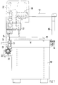
- the drilling machine has a machine frame 10 which also has cupboard compartments and can carry or receive devices for controlling the drilling machine.
- the machine frame 10 is closed with a workpiece support 11, which is provided in the area of the rear with a workpiece stop 12 which defines the position of the workpiece on the workpiece support 11.
- a guide rail 13 is attached along the front, while a guide shaft 14 is attached along the back.
- support roller pairs 18 or similar devices a supporting frame can be adjusted along the machine frame 10.
- This support frame has a pair of front vertical beams 15 and a pair of rear vertical beams 16.
- the multi-spindle drilling unit 20 has a plurality of rotatably arranged spindles 21, one of which is brought into the working position and receives the required tool.
- the spindle 21 in the working position is driven by a drive motor and is adjusted in the direction of the workpiece by an actuating device 22.
- the mode of operation and control of the multi-spindle drilling unit 20 need not be discussed in more detail here, since this is known and is not important for the present invention.
- roller bearings 32 are attached, which receive a position roller 30.
- the position roller 30 always has a specific axial position and can be rotatably and removably mounted in the roller bearings 32.
- the mounting of the holding rails 34 with fingers 37 thus depends on the spacing of the holes in a row of holes.
- the hole patterns can therefore be specified for eight rows of holes. It is provided that all holding rails 34 can be brought into a working position in which their positioned fingers 37 stand vertically upwards and can work together with a finger receptacle 23 attached to the supporting frame.
- the fingers 37 have a frustoconical head 38, which is followed by a hexagon or octagon 39 and a threaded bolt 40.
- the threaded bolt 40 is screwed into a nut 35 which is guided and held in the holding rail 34 after it has previously been inserted into the holding rail 34 through a bore in a fastening plate 36.
- a plurality of holding rails 34 can also be assigned to a row of bores, with other tools or other spindles 21 being assigned to the holding rails 34. In this way, rows of holes with different bores can be introduced in several adjustment movements of the multi-spindle drilling unit 20 in cooperation with a plurality of holding rails 34 of the positioning roller 30.
- the holding rails 34 of the position roller 30 and the spindles 21 of the multi-spindle drilling unit 20 are provided with coordinated markings. Only when the holding rail 34 provided with the same marking as the spindle 21 is in the working position is the correct assignment given and corresponds to the desired drilling pattern.
- the multi-spindle drilling unit 20 can be adjusted by means of adjusting spindles or the like on the horizontal guide rails 17 in order to be able to set the distance for the row of holes to be introduced from the workpiece stop 12.
- this setting can also be preset, as shown by the position roller 31, which is arranged parallel to a horizontal guide 17.
- This position roller 31 also has n holding rails 34 for holding fingers 37. These fingers 37 work together in the working position with a finger holder 25 attached to the multi-spindle drilling unit 20. With this position roller 31, the distances of the rows of holes from the workpiece stop 12 can be specified.
- the holding rails 34 of the position roller 31 can be assigned to different workpieces or can also be used to make rows of bores perpendicular to the front and rear of the workpiece support 11.
- the finger receptacles 23 and 25 are disengaged from the head by means of hand levers 24 and 26 38 of the finger 37 brought so that the support structure or the multi-spindle drilling unit 20 pass the finger 37 and can be brought into engagement with the next finger 37 in the holding rail 34.
- the working positions are exactly maintained when the finger receptacles 23 and 25 are adapted to the outer contour of the head 38 of the finger 37.
- the finger receptacles 23 and 25 can also be supported by means of springs on the support frame or on the multi-spindle drilling unit 20, so that the operative connection between the finger 37 and the finger receptacle 23 or 25 can be automatically canceled and restored with the application of force.
- the position rollers 30 and 31 can also have a different number of holding rails 34 and different lengths.
- An interchangeable attachment to the machine frame 10 and on the support frame is, however, to be preferred in any case, since preset position rollers 30 and 31 can be provided for different workpieces, so that the conversion of the drilling machine can be carried out very easily and quickly and with simple Position rollers.
Landscapes
- Life Sciences & Earth Sciences (AREA)
- Engineering & Computer Science (AREA)
- Mechanical Engineering (AREA)
- Wood Science & Technology (AREA)
- Forests & Forestry (AREA)
- Drilling And Boring (AREA)
Applications Claiming Priority (2)
| Application Number | Priority Date | Filing Date | Title |
|---|---|---|---|
| DE4129745 | 1991-09-06 | ||
| DE4129745A DE4129745C1 (fr) | 1991-09-06 | 1991-09-06 |
Publications (2)
| Publication Number | Publication Date |
|---|---|
| EP0536532A2 true EP0536532A2 (fr) | 1993-04-14 |
| EP0536532A3 EP0536532A3 (en) | 1993-07-14 |
Family
ID=6440069
Family Applications (1)
| Application Number | Title | Priority Date | Filing Date |
|---|---|---|---|
| EP19920115039 Withdrawn EP0536532A3 (en) | 1991-09-06 | 1992-09-03 | Drilling machine, especially for woodworking |
Country Status (4)
| Country | Link |
|---|---|
| US (1) | US5287899A (fr) |
| EP (1) | EP0536532A3 (fr) |
| CA (1) | CA2077526A1 (fr) |
| DE (1) | DE4129745C1 (fr) |
Cited By (5)
| Publication number | Priority date | Publication date | Assignee | Title |
|---|---|---|---|---|
| CN104552481A (zh) * | 2014-12-22 | 2015-04-29 | 圣鹿(苏州)环保新材料科技有限公司 | 一种家具板材表面平整打孔一体机 |
| CN108789654A (zh) * | 2018-06-19 | 2018-11-13 | 温州职业技术学院 | 一种木工钻孔防尘装置 |
| CN108908504A (zh) * | 2018-07-05 | 2018-11-30 | 东莞市闻誉实业有限公司 | 打孔照明机器 |
| CN109108319A (zh) * | 2018-06-27 | 2019-01-01 | 湖州新元素金属制品有限公司 | 一种便于调节打孔位置的金属制品生产用打孔装置 |
| CN111843377A (zh) * | 2020-06-30 | 2020-10-30 | 鲁西工业装备有限公司 | 一种提高化工装备多孔板内孔粗糙度的加工工艺 |
Families Citing this family (2)
| Publication number | Priority date | Publication date | Assignee | Title |
|---|---|---|---|---|
| CN103009080A (zh) * | 2012-11-30 | 2013-04-03 | 南通弘峰机电有限公司 | 一种镗用工装 |
| CN105415431B (zh) * | 2015-11-25 | 2018-05-08 | 惠安县拓丰信息技术有限公司 | 校准式打孔设备 |
Family Cites Families (8)
| Publication number | Priority date | Publication date | Assignee | Title |
|---|---|---|---|---|
| US481737A (en) * | 1892-08-30 | Work-holder for boring-machines | ||
| BE444063A (fr) * | 1939-08-17 | |||
| US2623419A (en) * | 1946-10-04 | 1952-12-30 | George F Wales | Precision drilling machine |
| BE502102A (fr) * | 1950-10-12 | |||
| CH315383A (fr) * | 1953-04-01 | 1956-08-15 | Genevoise Instr Physique | Machine-outil |
| IT955688B (it) * | 1972-05-20 | 1973-09-29 | Alberti Vittorio Spa | Perfezionamento alle macchine cosi dette fora rici multiple per l indu stria del legno ed alle relative metodologie di servizio delle stes se e foratrici multiple perfezio nate |
| DE7619306U1 (de) * | 1976-06-18 | 1977-01-13 | Priess, Wilfried, 4955 Hille | Bohrvorrichtung |
| AU4218978A (en) * | 1977-12-08 | 1979-06-14 | Wisse J R Van | Indexing means |
-
1991
- 1991-09-06 DE DE4129745A patent/DE4129745C1/de not_active Expired - Lifetime
-
1992
- 1992-09-03 CA CA002077526A patent/CA2077526A1/fr not_active Abandoned
- 1992-09-03 US US07/939,991 patent/US5287899A/en not_active Expired - Fee Related
- 1992-09-03 EP EP19920115039 patent/EP0536532A3/de not_active Withdrawn
Cited By (6)
| Publication number | Priority date | Publication date | Assignee | Title |
|---|---|---|---|---|
| CN104552481A (zh) * | 2014-12-22 | 2015-04-29 | 圣鹿(苏州)环保新材料科技有限公司 | 一种家具板材表面平整打孔一体机 |
| CN108789654A (zh) * | 2018-06-19 | 2018-11-13 | 温州职业技术学院 | 一种木工钻孔防尘装置 |
| CN109108319A (zh) * | 2018-06-27 | 2019-01-01 | 湖州新元素金属制品有限公司 | 一种便于调节打孔位置的金属制品生产用打孔装置 |
| CN109108319B (zh) * | 2018-06-27 | 2020-04-21 | 湖州新元素金属制品有限公司 | 一种便于调节打孔位置的金属制品生产用打孔装置 |
| CN108908504A (zh) * | 2018-07-05 | 2018-11-30 | 东莞市闻誉实业有限公司 | 打孔照明机器 |
| CN111843377A (zh) * | 2020-06-30 | 2020-10-30 | 鲁西工业装备有限公司 | 一种提高化工装备多孔板内孔粗糙度的加工工艺 |
Also Published As
| Publication number | Publication date |
|---|---|
| CA2077526A1 (fr) | 1993-03-07 |
| US5287899A (en) | 1994-02-22 |
| EP0536532A3 (en) | 1993-07-14 |
| DE4129745C1 (fr) | 1992-07-09 |
Similar Documents
| Publication | Publication Date | Title |
|---|---|---|
| AT400689B (de) | Bohrmaschine | |
| DE4129745C1 (fr) | ||
| DE102010005446A1 (de) | Vorrichtung zum Bearbeiten von großen Werkstücken mit einem Roboter | |
| DE2704415A1 (de) | Bohrmaschine, insbesondere fuer die holzverarbeitung | |
| DE4129743C1 (fr) | ||
| DE3233059A1 (de) | Tiefbohrmaschine | |
| DE8531605U1 (de) | Werkzeugmaschine, insbesondere zum Bohren und Fräsen von Leiterplatten | |
| DE4225836A1 (de) | Lochstanze | |
| DE2701516A1 (de) | Bohrkopf fuer mehrspindel-bohrmaschine | |
| DE4218933C2 (de) | Vorrichtung zum Bohren von Türbandbefestigungslöchern | |
| DE4311434A1 (de) | Rahmenweises Fertigen von Fenster- und Türrahmen | |
| EP0445363A1 (fr) | Dispositif de fraisage ou perçage | |
| DE4406381A1 (de) | Maschine zur Bearbeitung von stabförmigen Werkstücken | |
| DE3405529A1 (de) | Maschine zum bohren von loechern in plattenfoermige werkstuecke | |
| WO1999016576A1 (fr) | Machine-outil | |
| DE2722073A1 (de) | Bohrmaschine, insbesondere fuer die holzbearbeitung | |
| DE3414886C1 (de) | Werkzeugmaschine | |
| DE69608372T2 (de) | Werkzeugmaschine für Bearbeitungsvorgänge auf langgestreckten Werkstücken wie Profilen und dergleichen | |
| DE4121981A1 (de) | Vorrichtung zur halterung von werkstuecken bei lochstanzen | |
| DE2236145C2 (de) | Aufspanneinrichtung für eine Karosserierichtbank | |
| DE3906916A1 (de) | Bohr- und duebelsetzautomat | |
| DE4039345A1 (de) | Bohrmaschine zur herstellung von gleichen lochabstand aufweisenden lochreihen in werkstuecken | |
| DE2947260A1 (de) | Bohrmaschine | |
| AT254495B (de) | Dübellochbohrmaschine | |
| DE2315724B2 (de) | Vorrichtung zur abstuetzung von werkstuecken bzw. werkzeugen |
Legal Events
| Date | Code | Title | Description |
|---|---|---|---|
| PUAI | Public reference made under article 153(3) epc to a published international application that has entered the european phase |
Free format text: ORIGINAL CODE: 0009012 |
|
| AK | Designated contracting states |
Kind code of ref document: A2 Designated state(s): AT BE CH ES FR GB IT LI NL |
|
| PUAL | Search report despatched |
Free format text: ORIGINAL CODE: 0009013 |
|
| AK | Designated contracting states |
Kind code of ref document: A3 Designated state(s): AT BE CH ES FR GB IT LI NL |
|
| 17P | Request for examination filed |
Effective date: 19931022 |
|
| 17Q | First examination report despatched |
Effective date: 19940905 |
|
| 18D | Application deemed to be withdrawn |
Effective date: 19950805 |