EP0447700B1 - Coupleur à fibre optique - Google Patents
Coupleur à fibre optique Download PDFInfo
- Publication number
- EP0447700B1 EP0447700B1 EP90302943A EP90302943A EP0447700B1 EP 0447700 B1 EP0447700 B1 EP 0447700B1 EP 90302943 A EP90302943 A EP 90302943A EP 90302943 A EP90302943 A EP 90302943A EP 0447700 B1 EP0447700 B1 EP 0447700B1
- Authority
- EP
- European Patent Office
- Prior art keywords
- optical fiber
- fiber coupler
- diameter
- wavelength
- fused
- Prior art date
- Legal status (The legal status is an assumption and is not a legal conclusion. Google has not performed a legal analysis and makes no representation as to the accuracy of the status listed.)
- Expired - Lifetime
Links
- 239000013307 optical fiber Substances 0.000 title claims description 121
- 239000000835 fiber Substances 0.000 claims description 40
- 239000006185 dispersion Substances 0.000 claims description 33
- 239000011162 core material Substances 0.000 description 24
- 239000000463 material Substances 0.000 description 12
- 238000005452 bending Methods 0.000 description 11
- VYPSYNLAJGMNEJ-UHFFFAOYSA-N Silicium dioxide Chemical compound O=[Si]=O VYPSYNLAJGMNEJ-UHFFFAOYSA-N 0.000 description 10
- 230000003287 optical effect Effects 0.000 description 10
- 239000010453 quartz Substances 0.000 description 9
- 238000010168 coupling process Methods 0.000 description 8
- 230000008878 coupling Effects 0.000 description 7
- 238000005859 coupling reaction Methods 0.000 description 7
- 230000000644 propagated effect Effects 0.000 description 4
- 230000005540 biological transmission Effects 0.000 description 1
- 238000005253 cladding Methods 0.000 description 1
- 238000004891 communication Methods 0.000 description 1
- 230000001276 controlling effect Effects 0.000 description 1
- 230000000694 effects Effects 0.000 description 1
- 238000004519 manufacturing process Methods 0.000 description 1
- 230000001105 regulatory effect Effects 0.000 description 1
- 239000007858 starting material Substances 0.000 description 1
Images

Classifications
-
- G—PHYSICS
- G02—OPTICS
- G02B—OPTICAL ELEMENTS, SYSTEMS OR APPARATUS
- G02B6/00—Light guides; Structural details of arrangements comprising light guides and other optical elements, e.g. couplings
- G02B6/24—Coupling light guides
- G02B6/26—Optical coupling means
- G02B6/28—Optical coupling means having data bus means, i.e. plural waveguides interconnected and providing an inherently bidirectional system by mixing and splitting signals
- G02B6/293—Optical coupling means having data bus means, i.e. plural waveguides interconnected and providing an inherently bidirectional system by mixing and splitting signals with wavelength selective means
- G02B6/29331—Optical coupling means having data bus means, i.e. plural waveguides interconnected and providing an inherently bidirectional system by mixing and splitting signals with wavelength selective means operating by evanescent wave coupling
- G02B6/29332—Wavelength selective couplers, i.e. based on evanescent coupling between light guides, e.g. fused fibre couplers with transverse coupling between fibres having different propagation constant wavelength dependency
-
- G—PHYSICS
- G02—OPTICS
- G02B—OPTICAL ELEMENTS, SYSTEMS OR APPARATUS
- G02B6/00—Light guides; Structural details of arrangements comprising light guides and other optical elements, e.g. couplings
- G02B6/24—Coupling light guides
- G02B6/26—Optical coupling means
- G02B6/28—Optical coupling means having data bus means, i.e. plural waveguides interconnected and providing an inherently bidirectional system by mixing and splitting signals
- G02B6/2804—Optical coupling means having data bus means, i.e. plural waveguides interconnected and providing an inherently bidirectional system by mixing and splitting signals forming multipart couplers without wavelength selective elements, e.g. "T" couplers, star couplers
- G02B6/2821—Optical coupling means having data bus means, i.e. plural waveguides interconnected and providing an inherently bidirectional system by mixing and splitting signals forming multipart couplers without wavelength selective elements, e.g. "T" couplers, star couplers using lateral coupling between contiguous fibres to split or combine optical signals
- G02B6/2835—Optical coupling means having data bus means, i.e. plural waveguides interconnected and providing an inherently bidirectional system by mixing and splitting signals forming multipart couplers without wavelength selective elements, e.g. "T" couplers, star couplers using lateral coupling between contiguous fibres to split or combine optical signals formed or shaped by thermal treatment, e.g. couplers
Definitions
- the present invention concerns optical fiber couplers employed in communication systems.
- the above described optical fiber coupling technique has the following shortcoming:
- quartz glass single mode optical fiber is used to form the optical fiber coupler, because the properties of the material are such that very little light energy is lost through the lateral surface of the fiber, the fused-elongated region must be quite long in order to sufficiently achieve optical coupling.
- the resulting diameters of the component optical fibers in the fused-elongated region end up being considerably reduced.
- quartz optical fibers having an outer diameter of 125 ⁇ m
- the fibers have a final outer diameter in the order of 20 ⁇ m. Because of this effect, even a relatively small curvature in the optical fiber results in light leaking through the side of the fiber to the exterior with loss in light energy. With a larger amount of bending in the optical fiber, the bending losses become significant.
- the present invention provides an optical fiber coupler formed by fusing a section of each of two or more component optical fibers, and then elongating the fused section thereby forming a fused-elongated region which constitutes the optical fiber coupler, in which at least one of the component fibers is a single mode optical fiber having a parameter range in which the mode field diameter increases monotonically with decrease in the diameter of the optical fiber core.
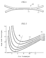
- Fig. 2 is a graph illustrating the relationship between core diameter and diameter of the mode field for a single mode optical fiber.
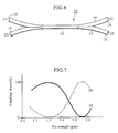
- Figs. 4 and 5 are graphs illustrating the relationship between wavelength and dispersion for the optical fibers.
- the optical fiber coupler 11 of the present embodiment as shown in Fig. 1 consists of a fused-elongated region 14 formed by thermally fusing and then drawing out a section of each of two component optical fibers 12 and 13, one of which is a conventional quartz single mode optical fiber 12 (hereafter referred to as conventional fiber), and one of which is a single mode optical fiber 13 characterized by having a parameter range in which the mode field diameter increases monotonically with decrease in the diameter of the optical fiber core.
- the fused-elongated region 14 thus manufactured had a minimum outer diameter of 45 ⁇ m, and a length of 7 mm.
- the measured value for loss from the thus produced optical fiber coupler 11 was 0.1 dB which is extremely low.
- optical fiber material for which the refractive index difference is high, and for which the core diameter is such that the structural parameters lie in the region to the left of the line 1B in Fig. 2.
- the so called wave guide dispersion is high.
- Figs. 4 and 5 examples of the wavelength dispersion characteristics can be seen for conventional optical fiber suitable for transmitting light signals at a wavelength of 1.3 ⁇ m of which the refractive index difference is high and of which the core diameter is small.
- the waveguide dispersion is low, and in the vicinity of 1.3 ⁇ m, the wavelength dispersion representing the sum of the wave guide dispersion and materials dispersion is zero.
- the mode propagation state also varies.
- the mode propagation velocity also varies.
- the propagation constant of the respective component optical fibers 12, 16 can be varied to match desired values.
- desired propagation constant for the two component fibers 12, 16 which are different and then thermally fusing together a portion of each component optical fiber 12, 16 and drawing out the fused portion as described above to form the fused-elongated region 17, the wavelength dependance characteristics of the resulting optical fiber coupler 15 can be controlled.
- an optical fiber coupler which is largely wavelength independent (or wide band-pass type optical fiber coupler) can be fabricated.
- the optical fiber coupler 19 of the present embodiment as shown in Fig. 6 consists of a fused-elongated region 20 formed by thermally fusing and then drawing out a section of each of two component optical fibers, both of which are the same as the dispersion shifted fiber 16 employed in the optical fiber coupler 15 described above for the second embodiment of the present invention.
- the fused-elongated region 20 thus manufactured had a minimum outer diameter of 55 ⁇ m, and a length of 10 mm.
Landscapes
- Physics & Mathematics (AREA)
- General Physics & Mathematics (AREA)
- Optics & Photonics (AREA)
- Optical Couplings Of Light Guides (AREA)
- Mechanical Coupling Of Light Guides (AREA)
Claims (3)
- Coupleur à fibres optiques formé en fondant une section de chacune de deux ou plusieurs fibres optiques élémentaires et en allongeant ensuite la section fondue pour former une région fondue et allongée dans laquelle au moins l'une desdites fibres optiques élémentaires est une fibre optique monomode ayant une gamme de paramètres telle que, quand le diamètre du coeur de ladite fibre optique est diminué, le diamètre du champ de mode de ladite fibre optique augmente de manière monotone.
- Coupleur à fibres optiques selon la revendication 1, dans lequel ladite fibre optique monomode est une fibre monomode à déplacement de dispersion, pour laquelle la valeur de la longueur d'onde à laquelle la dispersion de longueur d'onde devient égale à zéro est 1,4 µm ou plus grande.
- Coupleur à fibres optiques selon la revendication 1, dans lequel lesdites deux ou plusieurs fibres optiques élémentaires sont des fibres monomode à déplacement de dispersion, pour lesquelles la valeur de la longueur d'onde à laquelle la dispersion de longueur d'onde devient égale à zéro est 1,4 µm ou plus grande.
Priority Applications (2)
| Application Number | Priority Date | Filing Date | Title |
|---|---|---|---|
| DE1990614602 DE69014602T2 (de) | 1990-03-19 | 1990-03-19 | Faseroptischer Richtkoppler. |
| EP94107139A EP0610973B1 (fr) | 1990-03-07 | 1990-03-19 | Coupleur à fibre optique |
Applications Claiming Priority (1)
| Application Number | Priority Date | Filing Date | Title |
|---|---|---|---|
| US07/490,026 US5066087A (en) | 1990-03-07 | 1990-03-07 | Optical fiber coupler |
Related Child Applications (2)
| Application Number | Title | Priority Date | Filing Date |
|---|---|---|---|
| EP94107139A Division EP0610973B1 (fr) | 1990-03-07 | 1990-03-19 | Coupleur à fibre optique |
| EP94107139.1 Division-Into | 1990-03-19 |
Publications (2)
| Publication Number | Publication Date |
|---|---|
| EP0447700A1 EP0447700A1 (fr) | 1991-09-25 |
| EP0447700B1 true EP0447700B1 (fr) | 1994-11-30 |
Family
ID=23946309
Family Applications (2)
| Application Number | Title | Priority Date | Filing Date |
|---|---|---|---|
| EP94107139A Expired - Lifetime EP0610973B1 (fr) | 1990-03-07 | 1990-03-19 | Coupleur à fibre optique |
| EP90302943A Expired - Lifetime EP0447700B1 (fr) | 1990-03-07 | 1990-03-19 | Coupleur à fibre optique |
Family Applications Before (1)
| Application Number | Title | Priority Date | Filing Date |
|---|---|---|---|
| EP94107139A Expired - Lifetime EP0610973B1 (fr) | 1990-03-07 | 1990-03-19 | Coupleur à fibre optique |
Country Status (2)
| Country | Link |
|---|---|
| US (1) | US5066087A (fr) |
| EP (2) | EP0610973B1 (fr) |
Families Citing this family (14)
| Publication number | Priority date | Publication date | Assignee | Title |
|---|---|---|---|---|
| US5179603A (en) * | 1991-03-18 | 1993-01-12 | Corning Incorporated | Optical fiber amplifier and coupler |
| JPH04322207A (ja) * | 1991-04-23 | 1992-11-12 | Japan Aviation Electron Ind Ltd | 光ファイバカプラ |
| JPH05127040A (ja) * | 1991-11-06 | 1993-05-25 | Shin Etsu Chem Co Ltd | フアイバ型光カプラの保持具 |
| US5410626A (en) * | 1992-06-25 | 1995-04-25 | Kyocera Corporation | Optical coupler having a tapered fused region |
| JP3049697B2 (ja) * | 1992-07-29 | 2000-06-05 | 住友電気工業株式会社 | モードフィールド径変換ファイバ |
| US5355426A (en) * | 1992-09-02 | 1994-10-11 | Gould Electronics Inc. | Broadband MXN optical fiber couplers and method of making |
| US5303373A (en) * | 1992-10-16 | 1994-04-12 | Schott Fiber Optics, Inc. | Anamorphic fused fiber optic bundle |
| JPH06250042A (ja) * | 1993-03-01 | 1994-09-09 | Shin Etsu Chem Co Ltd | 広波長域光ファイバ型カプラおよびその製造方法 |
| JPH07318746A (ja) * | 1994-05-20 | 1995-12-08 | Seiko Giken:Kk | 結合部に高反射率の反射被覆をした光ファイバ光分岐合流器 |
| GB0219141D0 (en) * | 2002-08-16 | 2002-09-25 | Alcatel Optronics Uk Ltd | Optical branching component with low polarisation sensitivity |
| US6826341B2 (en) * | 2002-11-04 | 2004-11-30 | Fitel Usa Corp. | Systems and methods for reducing splice loss in optical fibers |
| GB2395796A (en) | 2002-11-27 | 2004-06-02 | Alcatel Optronics Uk Ltd | Optical waveguide branching component with MMI couplers |
| US7272280B2 (en) * | 2004-12-16 | 2007-09-18 | Honeywell International Inc. | Optical coupler for measuring wavelength |
| WO2009035104A1 (fr) * | 2007-09-14 | 2009-03-19 | Tatsuta Electric Wire & Cable Co., Ltd. | Fibre optique pour coupleur de fibres optiques et coupleur de fibres optiques |
Family Cites Families (7)
| Publication number | Priority date | Publication date | Assignee | Title |
|---|---|---|---|---|
| US4490163A (en) * | 1982-03-22 | 1984-12-25 | U.S. Philips Corporation | Method of manufacturing a fiber-optical coupling element |
| GB8519183D0 (en) * | 1985-07-30 | 1985-09-04 | British Telecomm | Optical fused couplers |
| DE8601064U1 (de) | 1986-01-17 | 1987-05-21 | Robert Bosch Gmbh, 7000 Stuttgart | Kraftstoff-Verteilereinspritzpumpe für Brennkraftmaschinen |
| GB2190762B (en) * | 1986-05-23 | 1989-12-13 | Stc Plc | Directional coupler |
| US4755037A (en) * | 1987-04-13 | 1988-07-05 | Mcdonnell Douglas Corporation | Fiber optic coupler |
| GB2207254B (en) * | 1987-07-11 | 1991-03-13 | Stc Plc | Glass clad optical fibre directional couplers. |
| JP2635720B2 (ja) * | 1988-10-18 | 1997-07-30 | 株式会社フジクラ | 光ファイバカプラ |
-
1990
- 1990-03-07 US US07/490,026 patent/US5066087A/en not_active Expired - Lifetime
- 1990-03-19 EP EP94107139A patent/EP0610973B1/fr not_active Expired - Lifetime
- 1990-03-19 EP EP90302943A patent/EP0447700B1/fr not_active Expired - Lifetime
Also Published As
| Publication number | Publication date |
|---|---|
| US5066087A (en) | 1991-11-19 |
| EP0610973B1 (fr) | 1999-01-13 |
| EP0447700A1 (fr) | 1991-09-25 |
| EP0610973A3 (fr) | 1995-01-18 |
| EP0610973A2 (fr) | 1994-08-17 |
Similar Documents
| Publication | Publication Date | Title |
|---|---|---|
| EP0447700B1 (fr) | Coupleur à fibre optique | |
| EP0783117B1 (fr) | Fibres optiques pour atténuation optique | |
| AU721745B2 (en) | Optical couplers with multilayer fibers | |
| US4798436A (en) | Optical fused couplers | |
| AU677819B2 (en) | Narrow band Mach-Zehnder filter | |
| EP0692722A2 (fr) | Atténuateur optique | |
| AU707442B2 (en) | Bragg grating filter | |
| JPH10232318A (ja) | 自己同調型光学導波路フィルタ | |
| CA2024225C (fr) | Coupleur de fibres optiques | |
| US4976512A (en) | Narrowband fiberoptic spectral filter formed from fibers having a refractive index with a W profile and a step profile | |
| US6088494A (en) | Aperiodic Mach-Zehnder optical filters | |
| EP0021712A1 (fr) | Guides d'ondes diélectriques et procédé de propagation des ondes électromagnétiques polarisées, dispositif de communication et système utilisant de tels guides d'ondes et un tel procédé | |
| US5559913A (en) | Broadband integrated optical proximity coupler | |
| KR100585016B1 (ko) | 고차 모드 제거 필터링 기능을 갖는 단일모드 광섬유 구조 | |
| JP3784593B2 (ja) | シングル・マルチモード光ファイバカプラ及びその製造方法 | |
| EP0308244A2 (fr) | Coupleur optique sélectif en longueur d'onde | |
| US4904040A (en) | Optical waveguide coupler for monitoring | |
| JP2635720B2 (ja) | 光ファイバカプラ | |
| JP2848832B2 (ja) | 広帯域形光ファイバカプラ | |
| US5946432A (en) | Periodic mach-zehnder optical filters | |
| JPH0750722Y2 (ja) | 光固定減衰器 | |
| CN1292883A (zh) | 宽带光器件上的光纤及其光纤器件 | |
| JPH10282341A (ja) | 光ファイバ型固定減衰器 | |
| Nolan | Multiply tapered fiber devices | |
| JPH04317013A (ja) | 光ファイバカプラ |
Legal Events
| Date | Code | Title | Description |
|---|---|---|---|
| PUAI | Public reference made under article 153(3) epc to a published international application that has entered the european phase |
Free format text: ORIGINAL CODE: 0009012 |
|
| 17P | Request for examination filed |
Effective date: 19901127 |
|
| AK | Designated contracting states |
Kind code of ref document: A1 Designated state(s): DE FR GB |
|
| 17Q | First examination report despatched |
Effective date: 19930511 |
|
| GRAA | (expected) grant |
Free format text: ORIGINAL CODE: 0009210 |
|
| AK | Designated contracting states |
Kind code of ref document: B1 Designated state(s): DE FR GB |
|
| XX | Miscellaneous (additional remarks) |
Free format text: TEILANMELDUNG 94107139.1 EINGEREICHT AM 14/10/91. |
|
| REF | Corresponds to: |
Ref document number: 69014602 Country of ref document: DE Date of ref document: 19950112 |
|
| ET | Fr: translation filed | ||
| PLBE | No opposition filed within time limit |
Free format text: ORIGINAL CODE: 0009261 |
|
| STAA | Information on the status of an ep patent application or granted ep patent |
Free format text: STATUS: NO OPPOSITION FILED WITHIN TIME LIMIT |
|
| 26N | No opposition filed | ||
| REG | Reference to a national code |
Ref country code: GB Ref legal event code: IF02 |
|
| PGFP | Annual fee paid to national office [announced via postgrant information from national office to epo] |
Ref country code: DE Payment date: 20080313 Year of fee payment: 19 |
|
| PGFP | Annual fee paid to national office [announced via postgrant information from national office to epo] |
Ref country code: GB Payment date: 20090318 Year of fee payment: 20 |
|
| PGFP | Annual fee paid to national office [announced via postgrant information from national office to epo] |
Ref country code: FR Payment date: 20090316 Year of fee payment: 20 |
|
| PG25 | Lapsed in a contracting state [announced via postgrant information from national office to epo] |
Ref country code: DE Free format text: LAPSE BECAUSE OF NON-PAYMENT OF DUE FEES Effective date: 20091001 |
|
| REG | Reference to a national code |
Ref country code: GB Ref legal event code: PE20 Expiry date: 20100318 |
|
| PG25 | Lapsed in a contracting state [announced via postgrant information from national office to epo] |
Ref country code: GB Free format text: LAPSE BECAUSE OF EXPIRATION OF PROTECTION Effective date: 20100318 |