EP0447720B1 - Lageweise aufgewickelte Spule von Trägerband für elektronische Bauelemente - Google Patents
Lageweise aufgewickelte Spule von Trägerband für elektronische Bauelemente Download PDFInfo
- Publication number
- EP0447720B1 EP0447720B1 EP90313864A EP90313864A EP0447720B1 EP 0447720 B1 EP0447720 B1 EP 0447720B1 EP 90313864 A EP90313864 A EP 90313864A EP 90313864 A EP90313864 A EP 90313864A EP 0447720 B1 EP0447720 B1 EP 0447720B1
- Authority
- EP
- European Patent Office
- Prior art keywords
- carrier tape
- hub
- millimeters
- reel
- width
- Prior art date
- Legal status (The legal status is an assumption and is not a legal conclusion. Google has not performed a legal analysis and makes no representation as to the accuracy of the status listed.)
- Expired - Lifetime
Links
- 230000002093 peripheral effect Effects 0.000 claims description 13
- 230000007704 transition Effects 0.000 description 8
- 239000000463 material Substances 0.000 description 4
- 238000004804 winding Methods 0.000 description 3
- KAKZBPTYRLMSJV-UHFFFAOYSA-N Butadiene Chemical compound C=CC=C KAKZBPTYRLMSJV-UHFFFAOYSA-N 0.000 description 2
- PPBRXRYQALVLMV-UHFFFAOYSA-N Styrene Chemical compound C=CC1=CC=CC=C1 PPBRXRYQALVLMV-UHFFFAOYSA-N 0.000 description 2
- 230000001186 cumulative effect Effects 0.000 description 2
- 238000011179 visual inspection Methods 0.000 description 2
- 239000004743 Polypropylene Substances 0.000 description 1
- 229920000122 acrylonitrile butadiene styrene Polymers 0.000 description 1
- 238000005452 bending Methods 0.000 description 1
- 239000003990 capacitor Substances 0.000 description 1
- 239000002178 crystalline material Substances 0.000 description 1
- 238000010586 diagram Methods 0.000 description 1
- 238000004519 manufacturing process Methods 0.000 description 1
- 229920000515 polycarbonate Polymers 0.000 description 1
- 239000004417 polycarbonate Substances 0.000 description 1
- 229920000728 polyester Polymers 0.000 description 1
- -1 polypropylene Polymers 0.000 description 1
- 229920001155 polypropylene Polymers 0.000 description 1
- 230000003014 reinforcing effect Effects 0.000 description 1
- 239000000523 sample Substances 0.000 description 1
- 229920001169 thermoplastic Polymers 0.000 description 1
- 239000004416 thermosoftening plastic Substances 0.000 description 1
Images


Classifications
-
- B—PERFORMING OPERATIONS; TRANSPORTING
- B65—CONVEYING; PACKING; STORING; HANDLING THIN OR FILAMENTARY MATERIAL
- B65H—HANDLING THIN OR FILAMENTARY MATERIAL, e.g. SHEETS, WEBS, CABLES
- B65H55/00—Wound packages of filamentary material
-
- B—PERFORMING OPERATIONS; TRANSPORTING
- B65—CONVEYING; PACKING; STORING; HANDLING THIN OR FILAMENTARY MATERIAL
- B65H—HANDLING THIN OR FILAMENTARY MATERIAL, e.g. SHEETS, WEBS, CABLES
- B65H49/00—Unwinding or paying-out filamentary material; Supporting, storing or transporting packages from which filamentary material is to be withdrawn or paid-out
-
- B—PERFORMING OPERATIONS; TRANSPORTING
- B65—CONVEYING; PACKING; STORING; HANDLING THIN OR FILAMENTARY MATERIAL
- B65H—HANDLING THIN OR FILAMENTARY MATERIAL, e.g. SHEETS, WEBS, CABLES
- B65H2701/00—Handled material; Storage means
- B65H2701/10—Handled articles or webs
- B65H2701/19—Specific article or web
- B65H2701/1942—Web supporting regularly spaced non-adhesive articles
-
- B—PERFORMING OPERATIONS; TRANSPORTING
- B65—CONVEYING; PACKING; STORING; HANDLING THIN OR FILAMENTARY MATERIAL
- B65H—HANDLING THIN OR FILAMENTARY MATERIAL, e.g. SHEETS, WEBS, CABLES
- B65H2701/00—Handled material; Storage means
- B65H2701/30—Handled filamentary material
- B65H2701/37—Tapes
Definitions
- the present invention relates to reels of component carrier tape (also called surface mount supplies carrier tape) of the type sent from the manufacturer of the carrier tape to a component manufacturer who will unwind the carrier tape from the reel and fill it with components.
- component carrier tape also called surface mount supplies carrier tape
- Surface mount supplies carrier tape or component carrier tape is used to transport components (e.g., electrical components such as resistors, capacitors, or integrated circuits) from a component manufacturer to a different manufacturer that assembles the components into new products, typically by having automated assembly equipment sequentially remove components from the carrier tape and assemble them into to the new products.
- components e.g., electrical components such as resistors, capacitors, or integrated circuits
- Such carrier tape is a polymeric strip that has been formed to have wall portions defining a series of identical pockets at predetermined uniformly spaced intervals along its length, which pockets are shaped to closely receive identical components the tape is adapted to transport (e.g., which pockets could, for example, have rectangular or generally "I” or “T” shapes in the plane of the strip, and could have flat or rounded bottoms to accommodate the shape of the components), which strip normally also has through openings uniformly spaced along one side to receive a drive sprocket by which the strip can be driven and to provide indexing holes that can be used for accurately locating the pockets along the tape with respect to assembly equipment.
- the carrier tape is manufactured in a first manufacturing location, wound on a reel and transported to the supplier of the components it is intended to transport.
- the component supplier unwinds the carrier tape from the reel, fills the pockets along the carrier tape with components, adheres a removable cover strip along the carrier tape over the component filled pockets, winds the component filled carrier tape with the attached cover strip onto a different typically smaller reel, and sends it to the user who feeds it from the reel into the assembly equipment which removes the components.
- the carrier tape must have less than 1 millimeter non cumulative camber over a length of 250 millimeters. This means that when the carrier tape is unwound from the reel on which it is shipped to the component supplier and disposed on a planar surface, its elongate edges must not deviate from being straight by more than 1 millimeter in any 250 millimeter length of the carrier tape.
- the component tape can easily be made to meet this specification. When the component tape is wound around a reel directly upon itself with the edges of all the wraps in a single plane for shipment to the component supplier (called “planetary winding" in the industry) it will remain generally as straight as it was when it was manufactured. Such planetary wound reels are limited in the amount of component tape they can hold, however.
- the present invention provides a planetary wound reel of carrier tape that will consistently meet the camber specification noted above, provided though the carrier tape as originally manufactured met that specification.
- Applicant has recognized that the inability of eight millimeter wide component tape shipped to component suppliers level wound edge to edge on reels with 203.2 millimeter (8 inch) outside diameter cores to consistently meet the camber specification noted above (even though the carrier tape as originally manufactured met that specification) was due to cold flow that occurs after the reel is level wound with the carrier tape in transition portions of the carrier tape adjacent the flanges of the reel in which the carrier tape changes its orientation with respect to the axis of the hub between successive layers of wraps, and has found a solution to that problem.
- Such a hub diameter (e.g., about 226 millimeters (8.9 inches) for 8 millimeter wide component carrier tape) should allow the component carrier tape to normally meet the camber specification noted above despite cold flow which will occur in the transition portions of the carrier tape, as will be explained in greater detail below, and meeting that specification for 8 millimeter wide component carrier tape can be virtually assured through use of even a larger preferred 355.6 millimeter (14 inch) diameter reel hub.
- combination 11 generally comprises (1) a length of component carrier tape 10 having elongate edges and a uniform width between its edges; and (2) a reel 14 including a hub 15 having an axis 16, opposite axially spaced ends and a cylindrical peripheral surface 18 between its ends, and a pair of flanges 19, one fixed to the hub 15 at each of its ends and projecting radially from the hub 15, the flanges 19 having opposed inner surfaces spaced by a distance (e.g., 76.2 millimeters or greater) significantly greater than the width of carrier tape 10.
- a distance e.g., 76.2 millimeters or greater
- the component carrier tape 10 is helically level wound around the peripheral surface 18 of the hub 15 in layers with the wraps of carrier tape 10 in each layer being disposed edge to edge so that those wraps are displaced axially from each other by the width of the carrier tape 10, with the opposite edges of wraps of carrier tape 10 in successive layers being angled in opposite directions with respect to the axis 16 of the hub 15, and with transition portions 20 of the carrier tape 10 located adjacent the flanges 19 of the reel 14 in which transition portions 20 the carrier tape 10 changes its orientation with respect to the axis 16 of the hub 15 between successive layers of wraps.
- the carrier tape 10 is unitary, can be made to have a variety of uniform widths between its edges (e.g., 8, 12, 16, 24, 32 or 44 millimeters), and is made of a thin polymeric material (e.g., any thermoplastic crystalline or non crystalline material such as polyester, polycarbonate, polypropylene, styrene, butadiene, ABS plastic, etc. in the range of about 0.012 to 0.04 centimeter thick, and typically 0.025 centimeter thick) so that it is flexible.
- the carrier tape 10 comprises a strip like portion 22 defining a top surface for the tape 10, and wall portions defining a multiplicity of similarly shaped pockets 24 spaced along the carrier tape 10 and opening through its top surface.
- the wall portions may or may not include anti nesting shoulders for restricting entry of side wall portions defining the pockets 24 in one wrap of the carrier tape 10 on a reel into the pockets 24 in a wrap of carrier tape 10 beneath it as is described and claimed in U.S. Patent No. 4,898,275 issued February 6, 1990, the content whereof is incorporated herein by reference.
- the carrier tape 10 also has a conventional series of equally spaced and sized through openings 26 along one edge of the strip like portion 22 which will receive the teeth of a drive sprocket by which the carrier tape 10 may be driven through automated equipment which loads components into the pockets 24 or removes components from the pockets 24.
- the carrier tape 10 has an opening generally centered in the bottom wall of each of the pockets 24 as is required by an industry standard to allow the presence of a component in a pocket 24 to be sensed, or to allow access for a probe that facilitates removal of a component from the pocket 24.
- the hub 15 of the reel 14 is preferably a stiff hollow cylindrical tube of paper material, and the flanges 19 are preferably discs of a corrugated cardboard material attached to the ends of the hub 15 by a plurality of staples 28.
- the flanges 19 have central openings 30 around which are fastened the ends of a hollow cylindrical reinforcing journal tube 31 (also of paper material) extending between the flanges 19 and through which openings 30 and tube 31 a spindle may be positioned to rotatably support the reel 14.
- the flanges also have radially extending openings 32 that afford visual inspection of the amount of component carrier tape 10 remaining on the reel 14, and drive openings 33 adjacent the openings 30 in which an external drive member may be positioned to afford rotational driving engagement with the reel 14.
- the flanges 19 of the reel 14 are compressed around their peripheries to restrict engaging the edges of component carrier tape 10 being wound onto or off of the hub 15, and may also be compressed or creased along rectangularly disposed lines 34 ending in the openings 32 to afford bending portions of the flanges 19 away from the opposite flange 19 along the lines 34 to either afford visual inspection of the amount of component carrier tape 10 remaining on the reel 14, or to reduce the diameter of the reel 14 to facilitate its disposal, preferably to a recycler of paper products.
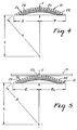
- Figure 5 there is illustrated one flange 19 of the reel 14 and successive wraps designated Z1 and Z2 of the component carrier tape 10 in different layers joined by one of the transition portions 20 of the component carrier tape 10 that are curved to allow those wraps Z1 and Z2 to be angled in opposite directions with respect to the axis 16 of the hub 15, and which curvature will result from cold flow in the carrier tape 10 caused by such angling in opposite directions.
- reels 14 with the minimum diameter hubs 15 that can be determined by the above formula (e.g., about 226 millimeters (8.9 inches) for 8 millimeter (0.31 inch) wide component carrier tape; about 274 millimeters (10.8 inches) for 12 millimeter (0.47 inch) wide component carrier tape; about 317.5 millimeters (12.5 inches) for 16 millimeter (0.63 inch) wide component carrier tape; about 388.6 millimeters (15.3 inches) for 24 millimeter (0.94 inch) wide component carrier tape; about 449.6 millimeters (17.7 inches) for 32 millimeter (1.26 inch) wide component carrier tape; about 527.1 millimeters (20.7 inches) for 44 millimeter (1.73 inch) wide component carrier tape; and about 594.4 millimeters (23.4 inches) for 56 millimeter (2.2 inch) wide component carrier tape) would provide little margin for errors that might occur in level winding on the carrier tape 10 or for the approximation described above that is incorporated in the formula.
- a reel 14 that has a hub 15 diameter that is significantly above the minimum diameters indicated by the above formula, such as a reel 14 with a 355.6 millimeter (14 inch) diameter for either 8 or 12 millimeter wide component carrier tapes 10.
Landscapes
- Storage Of Web-Like Or Filamentary Materials (AREA)
- Packaging Frangible Articles (AREA)
Claims (3)
- Kombination aus einem Trägerband (10) für elektronische Bauelemente mit langgestreckten Kanten und einem gleichmäßigen Abstand zwischen den Kanten; und
einer Spule (14) mit einer Nabe (15), die eine Achse (16), einander entgegengesetzte, axial beabstandete Enden und eine zylindrische Umfangsfläche (18) zwischen den Enden besitzt, und mit einem Paar Flansche (19), von denen einer an der Nabe (15) im Bereich jedes der Enden befestigt ist und radial von der Nabe (15) ausgeht, wobei die Flansche (19) einander gegenüberliegende Innenflächen besitzen, die um eine Strecke voneinander beabstandet sind, die deutlich größer ist als die Breite des Trägerbandes (10);
wobei das Bauteileträgerband (10) spiralförmig lageweise um die Umfangsfläche (18) der Nabe (15) gewickelt ist, und die Wicklungen des Trägerbandes (10) in jeder Lage Kante an Kante angeordnet sind, so daß diese Wicklungen um die Breite des Trägerbandes (10) axial voneinander versetzt sind, und die einander entgegengesetzten Kanten der Wicklungen des Trägerbandes (10) in aufeinanderfolgenden Lagen sind in bezug auf die Achse (16) der Nabe (15) in entgegengesetzte Richtungen abgewinkelt;
wobei die Umfangsfläche (18) der Nabe (15) einen Mindestdurchmesser "D" besitzt, der durch folgende Formel definiert ist:
- Kombination nach Anspruch 1, bei der die Breite des Trägerbandes (10) 8 Millimeter beträgt, und der Durchmesser des Kerns 355,6 Millimeter (14 Zoll) beträgt.
- Kombination nach Anspruch 1, bei der die Breite des Trägerbandes (10) 12 Millimeter beträgt, und der Durchmesser des Kerns 355,6 Millimeter (14 Zoll) beträgt.
Applications Claiming Priority (2)
| Application Number | Priority Date | Filing Date | Title |
|---|---|---|---|
| US49344090A | 1990-03-14 | 1990-03-14 | |
| US493440 | 1990-03-14 |
Publications (2)
| Publication Number | Publication Date |
|---|---|
| EP0447720A1 EP0447720A1 (de) | 1991-09-25 |
| EP0447720B1 true EP0447720B1 (de) | 1993-12-22 |
Family
ID=23960234
Family Applications (1)
| Application Number | Title | Priority Date | Filing Date |
|---|---|---|---|
| EP90313864A Expired - Lifetime EP0447720B1 (de) | 1990-03-14 | 1990-12-19 | Lageweise aufgewickelte Spule von Trägerband für elektronische Bauelemente |
Country Status (6)
| Country | Link |
|---|---|
| EP (1) | EP0447720B1 (de) |
| JP (1) | JP2846488B2 (de) |
| KR (1) | KR100223710B1 (de) |
| DE (1) | DE69005437T2 (de) |
| MY (1) | MY104631A (de) |
| PH (1) | PH30856A (de) |
Families Citing this family (4)
| Publication number | Priority date | Publication date | Assignee | Title |
|---|---|---|---|---|
| US7585444B2 (en) * | 2005-06-14 | 2009-09-08 | Illinois Tool Works Inc. | Method for reducing camber in coiled plastic ribbon or tape |
| JP6750354B2 (ja) * | 2015-07-22 | 2020-09-02 | マックス株式会社 | リール |
| CN109179016B (zh) * | 2018-08-09 | 2020-04-21 | 业成科技(成都)有限公司 | 卷材及其制备方法 |
| DE202024104215U1 (de) * | 2024-07-26 | 2025-10-29 | Tridonic Gmbh & Co. Kg | Wickelrolle für LED-Flextapes |
Family Cites Families (1)
| Publication number | Priority date | Publication date | Assignee | Title |
|---|---|---|---|---|
| US4898275A (en) * | 1989-05-25 | 1990-02-06 | Minnesota Mining And Manufacturing Company | Non nesting component carrier tape |
-
1990
- 1990-12-19 EP EP90313864A patent/EP0447720B1/de not_active Expired - Lifetime
- 1990-12-19 DE DE69005437T patent/DE69005437T2/de not_active Expired - Fee Related
-
1991
- 1991-03-04 MY MYPI91000332A patent/MY104631A/en unknown
- 1991-03-11 PH PH42112A patent/PH30856A/en unknown
- 1991-03-12 KR KR1019910003913A patent/KR100223710B1/ko not_active Expired - Fee Related
- 1991-03-13 JP JP3048261A patent/JP2846488B2/ja not_active Expired - Fee Related
Also Published As
| Publication number | Publication date |
|---|---|
| DE69005437T2 (de) | 1994-07-07 |
| JPH05221587A (ja) | 1993-08-31 |
| MY104631A (en) | 1994-04-30 |
| PH30856A (en) | 1997-12-09 |
| KR100223710B1 (ko) | 1999-10-15 |
| JP2846488B2 (ja) | 1999-01-13 |
| EP0447720A1 (de) | 1991-09-25 |
| DE69005437D1 (de) | 1994-02-03 |
| KR910016596A (ko) | 1991-11-05 |
Similar Documents
| Publication | Publication Date | Title |
|---|---|---|
| EP0399784B1 (de) | Nicht geschachteltes Trägerband für Bauteile | |
| US6145780A (en) | Portable device for dispensing cables | |
| US4019636A (en) | Strand package and carton therefor | |
| US5791590A (en) | Universal reel | |
| US4893438A (en) | Fan folded abrasive discs | |
| EP0758991A1 (de) | System zur abgabe von oberflächenmontierten teilen | |
| US2929496A (en) | Package for tape mounted materials | |
| EP0447720A1 (de) | Lageweise aufgewickelte Spule von Trägerband für elektronische Bauelemente | |
| US4756488A (en) | Reel core | |
| US5803396A (en) | Method for spooling a strip of wires, and a spooled strip of wires | |
| US4244503A (en) | Dispenser for flexible material | |
| CN103380062B (zh) | 用于存放、运输和分发传送带的装置 | |
| US7131608B2 (en) | Retail package for winding and storage of straps | |
| US5509620A (en) | Rotatable reel apparatus | |
| US5054704A (en) | Level wound reel of component carrier tape | |
| EP0116214B1 (de) | Verpackung für eine Draht- oder Kabelrolle und Verfahren zu ihrer Herstellung | |
| GB2041327A (en) | Package construction for coilable material and method of packaging and dispensing same | |
| US20050221043A1 (en) | Adhesive roller assembly | |
| US3940081A (en) | Flat core for web windings | |
| JP2542294B2 (ja) | 巻取心棒およびこの巻取心棒を有する巻物形成体 | |
| US5460268A (en) | Band apparatus for reel assembly | |
| CA1106822A (en) | Ribbon package | |
| JPS6217437Y2 (de) | ||
| JPH0754210Y2 (ja) | リール用プロテクター | |
| JPH0352671B2 (de) |
Legal Events
| Date | Code | Title | Description |
|---|---|---|---|
| PUAI | Public reference made under article 153(3) epc to a published international application that has entered the european phase |
Free format text: ORIGINAL CODE: 0009012 |
|
| 17P | Request for examination filed |
Effective date: 19901227 |
|
| AK | Designated contracting states |
Kind code of ref document: A1 Designated state(s): DE FR GB IT NL |
|
| 17Q | First examination report despatched |
Effective date: 19930217 |
|
| ITF | It: translation for a ep patent filed | ||
| GRAA | (expected) grant |
Free format text: ORIGINAL CODE: 0009210 |
|
| AK | Designated contracting states |
Kind code of ref document: B1 Designated state(s): DE FR GB IT NL |
|
| REF | Corresponds to: |
Ref document number: 69005437 Country of ref document: DE Date of ref document: 19940203 |
|
| ET | Fr: translation filed | ||
| PLBE | No opposition filed within time limit |
Free format text: ORIGINAL CODE: 0009261 |
|
| STAA | Information on the status of an ep patent application or granted ep patent |
Free format text: STATUS: NO OPPOSITION FILED WITHIN TIME LIMIT |
|
| 26N | No opposition filed | ||
| REG | Reference to a national code |
Ref country code: GB Ref legal event code: IF02 |
|
| PGFP | Annual fee paid to national office [announced via postgrant information from national office to epo] |
Ref country code: NL Payment date: 20041129 Year of fee payment: 15 |
|
| PGFP | Annual fee paid to national office [announced via postgrant information from national office to epo] |
Ref country code: GB Payment date: 20051214 Year of fee payment: 16 |
|
| PG25 | Lapsed in a contracting state [announced via postgrant information from national office to epo] |
Ref country code: IT Free format text: LAPSE BECAUSE OF NON-PAYMENT OF DUE FEES;WARNING: LAPSES OF ITALIAN PATENTS WITH EFFECTIVE DATE BEFORE 2007 MAY HAVE OCCURRED AT ANY TIME BEFORE 2007. THE CORRECT EFFECTIVE DATE MAY BE DIFFERENT FROM THE ONE RECORDED. Effective date: 20051219 |
|
| PG25 | Lapsed in a contracting state [announced via postgrant information from national office to epo] |
Ref country code: NL Free format text: LAPSE BECAUSE OF NON-PAYMENT OF DUE FEES Effective date: 20060701 |
|
| NLV4 | Nl: lapsed or anulled due to non-payment of the annual fee |
Effective date: 20060701 |
|
| GBPC | Gb: european patent ceased through non-payment of renewal fee |
Effective date: 20061219 |
|
| PG25 | Lapsed in a contracting state [announced via postgrant information from national office to epo] |
Ref country code: GB Free format text: LAPSE BECAUSE OF NON-PAYMENT OF DUE FEES Effective date: 20061219 |
|
| PGFP | Annual fee paid to national office [announced via postgrant information from national office to epo] |
Ref country code: DE Payment date: 20080131 Year of fee payment: 18 |
|
| PGFP | Annual fee paid to national office [announced via postgrant information from national office to epo] |
Ref country code: FR Payment date: 20071217 Year of fee payment: 18 |
|
| REG | Reference to a national code |
Ref country code: FR Ref legal event code: ST Effective date: 20090831 |
|
| PG25 | Lapsed in a contracting state [announced via postgrant information from national office to epo] |
Ref country code: DE Free format text: LAPSE BECAUSE OF NON-PAYMENT OF DUE FEES Effective date: 20090701 |
|
| PG25 | Lapsed in a contracting state [announced via postgrant information from national office to epo] |
Ref country code: FR Free format text: LAPSE BECAUSE OF NON-PAYMENT OF DUE FEES Effective date: 20081231 |