EP0447750B1 - Système de freinage avec au moins un circuit de freinage - Google Patents
Système de freinage avec au moins un circuit de freinage Download PDFInfo
- Publication number
- EP0447750B1 EP0447750B1 EP91100622A EP91100622A EP0447750B1 EP 0447750 B1 EP0447750 B1 EP 0447750B1 EP 91100622 A EP91100622 A EP 91100622A EP 91100622 A EP91100622 A EP 91100622A EP 0447750 B1 EP0447750 B1 EP 0447750B1
- Authority
- EP
- European Patent Office
- Prior art keywords
- freinage
- pression
- une
- par
- dispositif
- Prior art date
- Legal status (The legal status is an assumption and is not a legal conclusion. Google has not performed a legal analysis and makes no representation as to the accuracy of the status listed.)
- Expired - Lifetime
Links
Images

Classifications
-
- B—PERFORMING OPERATIONS; TRANSPORTING
- B60—VEHICLES IN GENERAL
- B60T—VEHICLE BRAKE CONTROL SYSTEMS OR PARTS THEREOF; BRAKE CONTROL SYSTEMS OR PARTS THEREOF, IN GENERAL; ARRANGEMENT OF BRAKING ELEMENTS ON VEHICLES IN GENERAL; PORTABLE DEVICES FOR PREVENTING UNWANTED MOVEMENT OF VEHICLES; VEHICLE MODIFICATIONS TO FACILITATE COOLING OF BRAKES
- B60T8/00—Arrangements for adjusting wheel-braking force to meet varying vehicular or ground-surface conditions, e.g. limiting or varying distribution of braking force
-
- B—PERFORMING OPERATIONS; TRANSPORTING
- B60—VEHICLES IN GENERAL
- B60T—VEHICLE BRAKE CONTROL SYSTEMS OR PARTS THEREOF; BRAKE CONTROL SYSTEMS OR PARTS THEREOF, IN GENERAL; ARRANGEMENT OF BRAKING ELEMENTS ON VEHICLES IN GENERAL; PORTABLE DEVICES FOR PREVENTING UNWANTED MOVEMENT OF VEHICLES; VEHICLE MODIFICATIONS TO FACILITATE COOLING OF BRAKES
- B60T13/00—Transmitting braking action from initiating means to ultimate brake actuator with power assistance or drive; Brake systems incorporating such transmitting means, e.g. air-pressure brake systems
- B60T13/10—Transmitting braking action from initiating means to ultimate brake actuator with power assistance or drive; Brake systems incorporating such transmitting means, e.g. air-pressure brake systems with fluid assistance, drive, or release
- B60T13/66—Electrical control in fluid-pressure brake systems
Definitions
- the invention relates to a brake system with at least one brake circuit actuated by supplying brake pressure and with a mechanical, redundant brake pressure controlling brake pressure control device and an electrical brake pressure control device according to the preamble of claim 1.
- Such a brake system is operated primarily by the electrical brake pressure control device. In the event of a fault in the electrical brake pressure control device, the brake system remains functional by means of the redundant brake pressure controlled by the mechanical brake pressure control device.
- Such a brake system is known from DE 35 01 179 A1.
- the brake pressure modulator of this brake system is designed as a blocking device with regard to the redundant brake pressure. For this purpose it is designed in such a way that when it is actuated in the sense of increasing or constant brake pressure it blocks its passage for the redundant brake pressure and when it is actuated in the sense of falling brake pressure this passage opens and thereby enables the desired brake pressure drop via the mechanical brake pressure control device.
- the known brake system is to contain one or more elements which cause a particularly rapid drop in brake pressure, then it must, as can be seen, for example, from FIG Elements the required quick Brake pressure drop guaranteed.
- Such elements are, for example, an anti-lock system and an overlying electrical or hydraulic permanent brake, usually called a retarder.
- the invention has for its object to prepare a brake system of the type mentioned without an additional device for the use of elements that cause a particularly rapid pressure drop.
- test routines are provided in the known brake system, in which the brake pressure modulator is automatically actuated in the sense of falling brake pressure when the brake system is actuated.
- the redundant brake pressure can pass as brake pressure to the output of the brake pressure modulator during the test routines.
- a pressure sensor of the control electronics used to monitor the brake pressure then indicates the level at which the redundant brake pressure is available.
- the invention can be developed with simple means so that it enables continuous monitoring of the redundant brake pressure when the brake is actuated.
- the invention can be carried out in connection with all suitable pressure media.
- the invention can be carried out inexpensively largely using commercially available devices.
- the pressure control valve described in DE 30 38 797 A1 can be used; in another embodiment, the brake pressure modulator can be produced, for example, from a customary magnetic proportional valve and a customary two-circuit relay valve device.
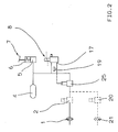
- FIG. 1 shows in solid lines the basic design of a brake system of a towing vehicle with a brake circuit actuated by supplying brake pressure with an application device (1) and with a mechanical brake pressure control device (5) and an electrical brake pressure control device (6, 8, 11, 19). Air serves as the pressure medium.
- the mechanical brake pressure control device consists of the pressure part (5) of a brake value transmitter (7).
- the electrical brake pressure control device (6, 8, 11, 19) consists of an electrical part (6) of the brake value transmitter (7), control electronics (11, 19), to which a control circuit (11) and a brake pressure sensor (19) belong, and a brake pressure modulator (8).
- the brake pressure modulator (8) is connected to an inlet (3) with a pressure supply (4) and at its outlet (17) to the application device (1). It is magnet and pressure operated. For actuating the pressure, it has a control device which is connected via another input (9) to the output of the pressure part (5) of the brake value transmitter (7) and is consequently acted upon by the redundant brake pressure. For solenoid actuation, it has an actuating magnet, which is not described in more detail.
- the pressure modulator (8) connects the application device (1) to the pressure supply (4) until a brake pressure has built up in the application device (1). the amount of which is measured both by the magnetic current supplied and by the level of the redundant brake pressure.
- the brake pressure emitted by the brake pressure modulator (8) is therefore composed of a brake pressure component based on the redundant brake pressure and on a brake pressure component.
- the brake pressure component due to the redundant brake pressure can be equal to or reduced or translated into the redundant brake pressure, i.e. lower or higher than the redundant brake pressure.
- the pressure control valve described in DE 30 38 797 A1 can be used as the brake pressure modulator (8). This is actuated by connecting its vent connection to the outlet of the pressure part (5) of the brake value transmitter (7) in the sense of the present invention.
- This brake pressure modulator measures the brake pressure by adding the brake pressure components due to its individual actuators. However, any other suitable type of brake pressure measurement can also be used.
- the pressure sensor (19) monitors the brake pressure modulator (8) at the output (17) of the brake pressure modulator (8) and supplies the control circuit (11) with a corresponding brake pressure signal.
- the brake value transmitter (7) When actuated by the driver, the brake value transmitter (7) emits on its electrical part (6) an electrical signal which is dependent on the actuating force or the actuation path, hereinafter referred to as the actuation signal; at the same time he controls on his pressure part (5) from the pressure supply (4) the redundant brake pressure, which also depends on the actuation variables mentioned.
- the brake pressure control device represented by the pressure part (5) is called "mechanical" because it converts the actuation variables introduced into the brake value transmitter (7) in a known manner with mechanical means into the redundant brake pressure.
- the control circuit (11) receives the actuation signal of the electrical part (6) of the brake value transmitter (7) and the brake pressure signal of the pressure sensor (19) and emits the magnet current required for its actuation to the magnet actuation of the brake pressure modulator (8).
- the control circuit (11) evaluates the actuation signal as a brake pressure request signal, compares it with the brake pressure signal and, in the event of a deviation, sets the magnet current to that for eliminating the deviation, i.e. to a value required to cover the respective brake pressure requirement.
- the control circuit (11) adjusts the magnet current so that the brake pressure component due to the magnet actuation makes up precisely the difference between the brake pressure request and the brake pressure component due to the redundant brake pressure.
- the electrical brake pressure control device (6, 8, 11, 19) and / or the mechanical brake pressure control device (8) can be designed such that, at least in the partial brake area, the brake pressure requirement is higher than the redundant brake pressure, so that at least in the partial brake area there is always one due to the magnet actuation Brake pressure component occurs and during full braking the brake value transmitter (7) requires a significantly increased actuation force or a significantly increased actuation path to control the full supply pressure as a redundant brake pressure.
- control circuit (11) can also store a target range for the mutual assignment of magnetic current strength and brake pressure when the pressure part (5) and the pressure actuation of the brake pressure modulator (8) function properly.
- control circuit (11) can also be designed such that, using the brake pressure signal, it determines the position of the magnetic current with respect to the desired range and emits a warning signal when the magnetic current leaves the desired range.
- control electronics (11, 19) can also be used to monitor the redundant brake pressure and thus the pressure part (5) and the pressure actuation of the pressure modulator (8) for intactness, because a magnetic current that falls outside the target range indicates that the pressure is too high or too low a brake pressure component due to the redundant brake pressure and thus to faults in the pressure part (5) and / or the pressure actuation of the pressure modulator (8) and / or associated pressure medium lines.
- FIG. 1 shows dashed lines of further further developments of the invention.
- a further application device (21) indicates that the brake circuit can also have several application devices.
- the further application devices can, as shown, on the brake pressure modulator (8) Basic equipment can be connected, but it can also be provided for each individual brake pressure modulators or their own brake pressure modulators.
- Control valves (2) and (20) of an anti-lock system not shown in the rest, hereinafter referred to as ABS valves, indicate that the brake system can also be equipped with an anti-lock system.
- the brake pressures in the application device (s) (1) or (21) and at the outlet (17) of the brake pressure modulator (8) can be different.
- Their control electronics can be wholly or partly combined with the control circuit (11).
- the ABS valves (2) and (20) have their own ventilation device in a known manner. As shown, they are arranged between the outlet (17) of the pressure modulator (8) and the application device (s) (1, 21). Therefore, if necessary, they enable a brake pressure drop in the application device (s) (1, 21) in the shortest possible way and therefore very quickly without any additional devices.
- the reference number (10) indicates at least one further signal transmitter, the signal of which the control circuit (11) evaluates in addition to the actuation signal of the electrical part (6) of the brake value transmitter (7) when determining the brake pressure request.
- One or more load sensors may be considered as such signal generators, for example, if the electrical brake pressure control device to be designated in this case with (6, 8, 10, 11, 19) contains a load-dependent brake pressure regulator.
- Additional or alternative signal transmitters include, for example, one or more retarder sensor (s), drawbar force sensor (s), Braking torque sensor (s), braking temperature sensor (s) and the like into consideration. In this training it can happen that the brake pressure component due to the redundant brake pressure already exceeds the braking force requirement. Adaptation is possible by arranging a restraint device indicated by (18) in the mechanical brake pressure control device, which is then designated by (5, 18), which restraint device (18) retains the redundant brake pressure up to a predetermined restraint pressure.
- the retention pressure can be a fixed pressure value or variable depending on the requirements of the specific application.
- a fixed pressure value is obtained when using a conventional overflow valve as a retention device.
- a variable retention pressure can be achieved, for example, by using a retention device according to the principles of the adaptation valves according to WABCO publications 975 001, March 1977 edition, or 975 002, August 1973 edition.
- Another exemplary possibility of making the restraint pressure variable is the design of the restraint device according to the principle of the load / empty valve shown in WABCO publication 973 300, January 1974 edition. In this case, as shown, the brake pressure could be supplied to the control input of the load / empty valve. If the electrical brake pressure control device contains a load-dependent brake pressure regulator, this configuration can be tailored specifically to this by designing the load / empty valve so that the retention pressure is at most equal to the brake pressure output by the brake pressure modulator (8) when the vehicle is empty.
- the entire brake pressure area can also be divided into a sub-area with wear-optimized braking and a sub-area in which it is more important to utilize the existing braking potential.
- the redundant brake pressure is below in the first section and above the restraining pressure in the second section.
- the exemplary embodiment contains a device for controlling a trailer brake system.
- This consists of a supply line (12) with a supply coupling (13) and an electrical and a pressure-actuated control device.
- the electrical control device consists of a control connection (14) and the control circuit (11), which is further developed for this purpose so that it receives the actuation signal received by the electrical part (6) of the brake value transmitter (7) and, if necessary, a part of the or converts all signal transmitters (10) into a trailer brake signal.
- the pressure-actuated control device consists of a trailer control valve (16) and an additional brake pressure modulator.
- the trailer control valve (16) corresponds to the usual pressure-actuated types.
- the additional brake pressure modulator basically corresponds to the brake pressure modulator (8) described above, but is partly installed differently from that; it is connected at its first inlet (3) to the supply line (12) and at its outlet (17) to a pressure control device of the trailer control valve (16). In a manner not shown, the output (17) of the additional brake pressure modulator (8) can also be connected directly to the trailer brake line.
- the magnetic actuation of this brake pressure modulator (8) is also supplied with magnetic current by the correspondingly designed control circuit (11).
- the training consists in the fact that the brake circuit contains a relay valve (25), which is connected upstream of the application device (1) or application devices (1, 21) in a conventional manner and whose control device is supplied with the brake pressure emitted by the brake pressure modulator (8) as control pressure becomes.
- the brake pressure sensor (19) is shown at the output of the brake pressure modulator (8), but can also be arranged at the output of the relay valve (25).
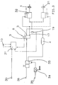
- Figure 3 shows in solid lines the basic design of a braking system of a trailer.
- the mechanical brake pressure control device (33, 34) in this case consists of a trailer brake valve (33) and a load-dependent brake pressure regulator (34). Both are of known types and arranged in the usual way. Consequently, the trailer brake valve (33) also serves to transfer the pressure medium supplied from the towing vehicle via a supply coupling (36) to the pressure supply (4) and it is arranged via a brake coupling (35) and a control line in which the load-dependent brake pressure regulator (3) is also arranged is driven.
- the load-dependent brake pressure regulator (34) can also be omitted.
- the electrical brake pressure control device (30, 8, 31, 19) consists of an electrical control connection (30), the control electronics (31, 19), to which a control circuit (31) and a pressure sensor (19) belong, and a brake pressure modulator.
- the brake pressure modulator, again designated by (8), and the brake pressure sensor, again designated by (19), correspond in principle to the components of the earlier exemplary embodiment that are identified by the same name.
- the control connection (30) receives the trailer brake signal generated in the towing vehicle and feeds it to the control circuit (31).
- the brake pressure modulator (8) is connected at one input (3) to the pressure supply (4) and at its other input (9) to the output of the trailer brake valve (33).
- the brake value modulator (8) is connected to the pressure control device of a relay valve (32), which also has a solenoid actuation and is thereby also a solenoid-controlled control valve of an anti-lock system.
- a relay valve also called ABS relay valve
- ABS relay valve is described for example in DE 37 30 779 A1.
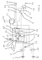
- FIG. 4 shows the exemplary embodiment according to FIG. 1 with a different embodiment of the brake pressure modulator.
- the brake pressure modulator generally designated here with (41), consists of a two-circuit relay valve device (44) and a solenoid-operated valve device (40).
- the two-circuit relay valve device (44) is of a commercially available top-up type. In this context, “topping up” means that when its two control devices are pressurized at the same time, it releases a higher pressure at its outlet than when only one of its control devices is pressurized.
- the valve device (40) is designed in a known manner in such a way that it modulates a pressure which is dependent on the magnetic current strength supplied.
- a commercially available magnetic proportional valve can be used, for example.
- a line comprising both of the aforementioned valve devices (40) and (44) indicates that these are assembled to form the brake pressure modulator (41).
- they can also perform the function of the brake pressure modulator (41) as individual devices that are connected to one another on the pressure side.
- One input (3), the other input (9) and the output (17) of the brake pressure modulator (41) are shown as connection points of the corresponding pressure medium lines to the mentioned line; If the valve device (40) and the two-circuit relay valve device (44) are arranged separately, the inputs (3) and (9) and the output (17) can coincide with connections of the valve device (40) and the two-circuit relay valve device (44).
- the valve device (40) is connected to one inlet (3) at its pressure medium inlet.
- the two-circuit relay valve device (44) is also connected to one input (3) at its supply connection, at one control device (42) to the outlet of the valve device (40), at its other control device (43) to the second input (9). and connected at its output to the output (17).
- the actuating magnet of the valve device (40) represents the magnet actuation of the brake pressure modulator (41).
- the two-circuit relay valve device (44 ) controlled both by the pressure controlled by the valve device (40) and by the pressure emitted by the mechanical brake pressure control device (5) or (5, 18). Since the pressure emitted by the valve device (40) depends on the current strength supplied to the actuating magnet, the control of the two-circuit relay valve device (44) on the control device (42) is dependent on this magnetic current strength.
- valve device (40) and the two-circuit relay valve device (44) provide the same functions in connection with one another as the brake pressure modulator (8) of the exemplary embodiment according to FIG. 1.
- the brake pressure modulator (8) can also be used in the others mentioned above Arrangements and in general, possibly with simple adaptation measures, are replaced by the brake pressure modulator (41).
Landscapes
- Engineering & Computer Science (AREA)
- Transportation (AREA)
- Mechanical Engineering (AREA)
- Regulating Braking Force (AREA)
- Braking Systems And Boosters (AREA)
- Valves And Accessory Devices For Braking Systems (AREA)
Claims (12)
- A brake system having at least one brake circuit actuated by admission of brake pressure and having a mechanical brake pressure control arrangement (5; 5, 18; 33, 34) issuing auxiliary brake pressure, and an electrical brake pressure control arrangement (6, 8, 11, 19; 6, 8, 10, 11, 19; 6, 41, 11, 19; 6, 41, 10, 11, 19; 30, 8, 31, 19; 30, 8, 10, 31, 19) which includes at least one magnetically-actuated brake pressure modulator (8; 41) associated with the brake circuit and an electronic control assembly (11, 19; 31, 19) controlling the brake pressure modulator (8; 41), wherein the brake pressure modulator (8; 41) is connected at one input (3) to a pressure reservoir (4), at another input (9) to the mechanical brake pressure control arrangement (5; 5, 18; 33, 34) and, at its output (17) delivering the brake pressure, to the brake circuit,
characterized in that
the brake pressure modulator (8; 41) is of a construction that is also pressure-controlled which calculates the brake pressure both according to the magnetizing current strength supplied and according to the level of the auxiliary brake pressure, and the electronic control assembly (11, 19; 31, 19) is constructed so that it adjusts the magnetizing current strength to a value required to cover the particular brake pressure requirement. - A brake system according to claim 1, characterized in that the electronic control assembly (11, 19; 31, 19) produces a warning signal whenever the magnetizing current strength departs from a predetermined desired range.
- A brake system according to one of Claims 1 or 2, characterized in that the brake pressure modulator (41) consists of a dual-circuit relay valve arrangement (44) and a magnetically-actuated valve arrangement (40) delivering pressure in dependence on the magnetizing current strength supplied to it and connected at its input to the one input (3), wherein the relay valve arrangement (44) is connected at its one control arrangement (42) to the output of the magnetically-actuated valve arrangement (40), at its other control arrangement (43) to the other input (9), at its output to the output (17) and at its reservoir connection to the one input (3).
- A brake system according to one of the preceding claims, characterized in that the mechanical brake pressure control arrangement (5; 18) comprises a retention device (18) which holds back the auxiliary brake pressure up to a predetermined retention pressure.
- A brake system according to claim 4, characterized in that the retention pressure is a function of the brake pressure issued from the brake: pressure modulator (8; 41).
- A brake system according to one of claims 4 or 5, in which the electrical brake pressure control arrangement (6, 8, 10, 11, 19) contains a load-dependent brake pressure regulator, characterized in that the retention pressure is at most the same as the brake pressure issued from the brake: pressure modulator (8; 41) when the vehicle is unloaded.
- A brake system according to one of claims 4 or 6, characterized in that the retention device (18) is an overflow valve.
- A brake system according to one of claims 4 to 6, characterized in that the retention device (18) is a load/no-load valve.
- A brake system according to one of the preceding claims, characterized in that at least in the partial braking range the brake pressure requirement is greater than the auxiliary brake pressure.
- A brake system according to one of the preceding claims, characterized in that the brake circuit contains at least one relay valve (25; 32) the control arrangement of which is supplied with the brake pressure delivered from the brake pressure modulator (8; 41) as control pressure.
- A brake system according to claim 10, characterized in that the relay valve (32) also serves as a magnetically-actuated control valve of an anti-lock system.
- A brake system according to one of the preceding claims, with a pressure-controlled trailer control valve (16), characterized in that an additional brake pressure modulator (8; 41) of the kind specified in Claim 1 is provided, and a pressure control arrangement of the trailer control valve (16) is connected to the output (17) of the additional brake pressure modulator (8; 41).
Applications Claiming Priority (4)
| Application Number | Priority Date | Filing Date | Title |
|---|---|---|---|
| DE4008601 | 1990-03-17 | ||
| DE4008601 | 1990-03-17 | ||
| DE4016463A DE4016463A1 (de) | 1990-03-17 | 1990-05-22 | Bremsanlage mit wenigstens einem bremskreis |
| DE4016463 | 1990-05-22 |
Publications (2)
| Publication Number | Publication Date |
|---|---|
| EP0447750A1 EP0447750A1 (fr) | 1991-09-25 |
| EP0447750B1 true EP0447750B1 (fr) | 1993-09-01 |
Family
ID=25891242
Family Applications (1)
| Application Number | Title | Priority Date | Filing Date |
|---|---|---|---|
| EP91100622A Expired - Lifetime EP0447750B1 (fr) | 1990-03-17 | 1991-01-19 | Système de freinage avec au moins un circuit de freinage |
Country Status (6)
| Country | Link |
|---|---|
| US (1) | US5294190A (fr) |
| EP (1) | EP0447750B1 (fr) |
| JP (1) | JP2757270B2 (fr) |
| DE (2) | DE4016463A1 (fr) |
| ES (1) | ES2044622T3 (fr) |
| PL (1) | PL164912B1 (fr) |
Cited By (3)
| Publication number | Priority date | Publication date | Assignee | Title |
|---|---|---|---|---|
| FR2698332A1 (fr) * | 1992-11-26 | 1994-05-27 | Renault | Procédé de commande de la décélération par freinage d'un véhicule routier et véhicule routier en faisant application. |
| EP1000830A2 (fr) | 1998-11-13 | 2000-05-17 | WABCO GmbH | Ajusteur de commande de frein à redondance d'addition intégrée |
| DE10042215C5 (de) * | 2000-08-28 | 2005-09-01 | Knorr-Bremse Systeme für Nutzfahrzeuge GmbH | Druckmittelbetätigte Fahrzeugbremsanlage mit redundanter Ansteuerung wenigstens eines Bremszylinders |
Families Citing this family (27)
| Publication number | Priority date | Publication date | Assignee | Title |
|---|---|---|---|---|
| ES2096213T3 (es) * | 1992-09-03 | 1997-03-01 | Grau Ltd | Sistema de frenado. |
| DE4232492C2 (de) * | 1992-09-28 | 1995-03-30 | Grau Gmbh | Betriebsbremsventil für eine elektrisch oder pneumatisch betätigbare Bremsanlage eines Kraftfahrzeugs |
| DE4242887A1 (de) * | 1992-12-18 | 1994-06-23 | Wabco Westinghouse Fahrzeug | Bremsanlage mit wenigstens einer Bremse |
| FR2701531B1 (fr) † | 1993-02-12 | 1995-04-28 | Alliedsignal Europ Services | Electrovalve pneumatique proportionnelle. |
| US5370449A (en) * | 1993-10-12 | 1994-12-06 | Eaton Corporation | Electrically operated parking brake system |
| WO1995016594A1 (fr) * | 1993-12-17 | 1995-06-22 | Knorr-Bremse Systeme für Nutzfahrzeuge GmbH | Systeme de freinage electropneumatique pour vehicules automobiles |
| DE69713750T2 (de) * | 1996-04-17 | 2003-03-13 | Lucas Industries Ltd., Solihull | Verbesserungen in hydraulischen fahrzeug-bremsanlagen mit elektrischer steuerung |
| US5758929A (en) * | 1996-09-11 | 1998-06-02 | New York Air Brake Corporation | Variable capacity electropneumatic control valve |
| DE19755431A1 (de) | 1997-12-13 | 1999-06-17 | Wabco Gmbh | Fahrzeugbremsanlage |
| US6179390B1 (en) * | 1998-04-24 | 2001-01-30 | Saturn Electronics & Engineering, Inc. | Electronic trailer brake controller |
| SE516430C2 (sv) * | 2000-05-05 | 2002-01-15 | Volvo Articulated Haulers Ab | Anordning och förfarande för aktivering av en nödbromsfunktion hos ett fordon |
| US6994381B1 (en) | 2000-07-20 | 2006-02-07 | Contech Construction Products Inc. | Stab joint coupling |
| DE10053607A1 (de) * | 2000-10-28 | 2002-05-02 | Bosch Gmbh Robert | Anordnung und Verfahren zum Bestimmen der Temperatur von Ventilen |
| US6527348B2 (en) * | 2001-05-22 | 2003-03-04 | Caterpillar Inc | Braking system for a construction machine |
| US6485111B2 (en) | 2000-12-22 | 2002-11-26 | Visteon Global Technologies, Inc. | Power assisted braking system |
| US6626506B2 (en) * | 2001-04-23 | 2003-09-30 | Westinghouse Air Brake Technologies Corporation | Method and apparatus for controlling electro-pneumatic braking on a train |
| DE10133440C2 (de) * | 2001-07-10 | 2003-06-18 | Knorr Bremse Systeme | Bremsanlage mit elektropneumatischem Modulator |
| DE10156673A1 (de) * | 2001-11-17 | 2003-05-28 | Wabco Gmbh & Co Ohg | Verfahren zum Betrieb einer elektrisch gesteuerten Druckmittelbremsanlage |
| DE10158065B4 (de) * | 2001-11-27 | 2010-09-23 | Wabco Gmbh | Redundanzdruck-Umschaltventil für elektronisch-pneumatische Bremsanlage |
| US20040130207A1 (en) * | 2003-01-07 | 2004-07-08 | Westinghouse Air Brake Technologies | Three state magnet valve |
| DE102012003106C5 (de) | 2012-02-16 | 2022-01-27 | Knorr-Bremse Systeme für Nutzfahrzeuge GmbH | Verfahren zur Bestimmung eines Bremsdruckwerts anhand von Kennlinien |
| US8783791B2 (en) | 2012-05-30 | 2014-07-22 | Bendix Commercial Vehicle Systems Llc | Dual circuit pneumatic foot valve with electronically controlled proportional modulator (ECPM) and operator input sensing |
| DE102016004489A1 (de) | 2016-04-18 | 2017-10-19 | Wabco Gmbh | Fahrer-Bremsventil, Druckluft-Bremssystem mit dem Fahrer-Bremsventil und Verfahren zur Herstellung des Fahrer-Bremsventils |
| GB201722251D0 (en) * | 2017-12-29 | 2018-02-14 | Agco Int Gmbh | Load-dependent trailer brake system and method of controlling such |
| EP3626558B1 (fr) * | 2018-09-18 | 2022-10-26 | KNORR-BREMSE Systeme für Nutzfahrzeuge GmbH | Système de frein pour véhicule |
| US11511716B2 (en) | 2019-06-12 | 2022-11-29 | Bendix Commercial Vehicle Systems Llc | EBS tractor control line to trailer system to improve transmission timing for an air brake system |
| DE102021112831A1 (de) * | 2021-05-18 | 2022-11-24 | Zf Cv Systems Global Gmbh | Elektropneumatische Baueinheit mit integrierter Ausfallsicherheitsventilanordnung für Mehrfachfehler, elektronisch steuerbares pneumatisches Bremssystem, sowie Verfahren zum Betreiben eines Bremssystems |
Family Cites Families (14)
| Publication number | Priority date | Publication date | Assignee | Title |
|---|---|---|---|---|
| FR2133591B1 (fr) * | 1971-04-16 | 1977-06-17 | Bendix Corp | |
| DE2939907A1 (de) * | 1979-10-02 | 1981-05-07 | Wabco Fahrzeugbremsen Gmbh, 3000 Hannover | Zweikreis-bremsanlage |
| DE3205228C2 (de) * | 1982-02-13 | 1999-04-01 | Bosch Gmbh Robert | Mehrkreis-Druckmittel-Bremsanlage |
| DE3207793A1 (de) * | 1982-03-04 | 1983-09-08 | Robert Bosch Gmbh, 7000 Stuttgart | Wagenzugbremsanlage |
| DE3212930A1 (de) * | 1982-04-07 | 1983-10-13 | Robert Bosch Gmbh, 7000 Stuttgart | Mehrkreis-bremsanlage ii |
| DE3215475A1 (de) * | 1982-04-24 | 1983-11-03 | Robert Bosch Gmbh, 7000 Stuttgart | Elektro-pneumatische bremsanlage |
| DE3219140C2 (de) * | 1982-05-21 | 1995-03-16 | Bosch Gmbh Robert | Wagenzug-Bremsanlage |
| DE3230971A1 (de) * | 1982-08-20 | 1984-04-12 | Robert Bosch Gmbh, 7000 Stuttgart | Mehrkreis-bremsanlage |
| DE3239970A1 (de) * | 1982-10-28 | 1984-07-12 | Robert Bosch Gmbh, 7000 Stuttgart | Wagenzug-bremsanlage |
| DE3240276A1 (de) * | 1982-10-30 | 1984-05-03 | Robert Bosch Gmbh, 7000 Stuttgart | Drucksteuerventil fuer eine bremsanlage |
| DE3416338A1 (de) * | 1984-05-03 | 1985-11-07 | Wabco Westinghouse Fahrzeugbremsen GmbH, 3000 Hannover | Einrichtung zur anpassung der bremskraftverteilung |
| DE3501179A1 (de) * | 1985-01-16 | 1986-07-17 | Wabco Westinghouse Fahrzeugbremsen GmbH, 3000 Hannover | Elektrische bremsanlage |
| DE3603143A1 (de) * | 1986-02-01 | 1987-08-06 | Bosch Gmbh Robert | Elektro-pneumatische bremsanlage |
| DE3703639A1 (de) * | 1987-02-06 | 1988-08-18 | Bosch Gmbh Robert | Elektro-pneumatische bremsanlage fuer zugfahrzeuge |
-
1990
- 1990-05-22 DE DE4016463A patent/DE4016463A1/de not_active Withdrawn
-
1991
- 1991-01-19 ES ES91100622T patent/ES2044622T3/es not_active Expired - Lifetime
- 1991-01-19 EP EP91100622A patent/EP0447750B1/fr not_active Expired - Lifetime
- 1991-01-19 DE DE91100622T patent/DE59100334D1/de not_active Expired - Lifetime
- 1991-03-05 US US07/664,880 patent/US5294190A/en not_active Expired - Lifetime
- 1991-03-07 JP JP3123291A patent/JP2757270B2/ja not_active Expired - Lifetime
- 1991-03-11 PL PL91289379A patent/PL164912B1/pl not_active IP Right Cessation
Cited By (4)
| Publication number | Priority date | Publication date | Assignee | Title |
|---|---|---|---|---|
| FR2698332A1 (fr) * | 1992-11-26 | 1994-05-27 | Renault | Procédé de commande de la décélération par freinage d'un véhicule routier et véhicule routier en faisant application. |
| EP1000830A2 (fr) | 1998-11-13 | 2000-05-17 | WABCO GmbH | Ajusteur de commande de frein à redondance d'addition intégrée |
| US6354671B1 (en) | 1998-11-13 | 2002-03-12 | Wabco Gmbh | Brake signal transmitter with integrated addition redundancy |
| DE10042215C5 (de) * | 2000-08-28 | 2005-09-01 | Knorr-Bremse Systeme für Nutzfahrzeuge GmbH | Druckmittelbetätigte Fahrzeugbremsanlage mit redundanter Ansteuerung wenigstens eines Bremszylinders |
Also Published As
| Publication number | Publication date |
|---|---|
| DE59100334D1 (de) | 1993-10-07 |
| JP2757270B2 (ja) | 1998-05-25 |
| EP0447750A1 (fr) | 1991-09-25 |
| US5294190A (en) | 1994-03-15 |
| PL164912B1 (pl) | 1994-10-31 |
| ES2044622T3 (es) | 1994-01-01 |
| JPH04228347A (ja) | 1992-08-18 |
| DE4016463A1 (de) | 1991-09-19 |
| PL289379A1 (en) | 1991-11-04 |
Similar Documents
| Publication | Publication Date | Title |
|---|---|---|
| EP0447750B1 (fr) | Système de freinage avec au moins un circuit de freinage | |
| EP1464557B1 (fr) | Dispositif de traitement d'air comprimé | |
| DE69410508T2 (de) | Elektrohydraulische Bremsvorrichtung für das Fahrwerk eines Flugzeugs | |
| DE4340467C2 (de) | Mit Fremdkraft arbeitende hydraulische Fahrzeugbremsanlage | |
| DE3789194T2 (de) | Regeleinrichtung für Fahrzeugbremsdruck. | |
| EP0307579B1 (fr) | Installation de valves commandées magnétiquement | |
| DE3102227C2 (fr) | ||
| EP0733532B1 (fr) | Procédé de détermination de la pression de déclenchement d'un frein actionné par pression dans un système de freinage de véhicule | |
| DE3124755A1 (de) | Fahrzeugbremsanlage | |
| EP0813481B1 (fr) | Systeme de regulation de la pression de freinage | |
| DE69121707T2 (de) | Ventil für automatisches bremssystem | |
| DE3410083A1 (de) | Druckbetaetigte bremsanlage fuer kraftfahrzeuge | |
| DE3423944A1 (de) | Fahrzeugbremsanlage | |
| DE69104476T2 (de) | Elektrohydraulische oder elektropneumatische bremsregelvorrichtung für anhängerachsen mit hilfskraftbremsen. | |
| EP0733531B1 (fr) | Procédé de freinage d'un véhicule | |
| DE3818617C2 (fr) | ||
| DE3312981C2 (fr) | ||
| EP0530460B1 (fr) | Système de freinage pour remorque | |
| DE102008009948B3 (de) | Bremsanlage für Nutzfahrzeuge | |
| EP0569697B1 (fr) | Procédé pour contrÔle de surcharge d'un frein d'un remorque d'un convoi routier | |
| DE2737938A1 (de) | Hydraulische antiblockiervorrichtung | |
| DE3545021A1 (de) | Elektro-pneumatische bremsanlage | |
| DE19633835B4 (de) | Verfahren zur Steuerung der Bremsanlage eines Fahrzeuges | |
| DE4004502C2 (fr) | ||
| EP0569698B1 (fr) | Procédé pour contrÔle de surcharge d'un frein d'un tracteur d'un convoi routier |
Legal Events
| Date | Code | Title | Description |
|---|---|---|---|
| PUAI | Public reference made under article 153(3) epc to a published international application that has entered the european phase |
Free format text: ORIGINAL CODE: 0009012 |
|
| 17P | Request for examination filed |
Effective date: 19910708 |
|
| AK | Designated contracting states |
Kind code of ref document: A1 Designated state(s): DE ES FR GB IT NL SE |
|
| 17Q | First examination report despatched |
Effective date: 19921217 |
|
| RAP1 | Party data changed (applicant data changed or rights of an application transferred) |
Owner name: WABCO VERMOEGENSVERWALTUNGS-GMBH |
|
| GRAA | (expected) grant |
Free format text: ORIGINAL CODE: 0009210 |
|
| AK | Designated contracting states |
Kind code of ref document: B1 Designated state(s): DE ES FR GB IT NL SE |
|
| REF | Corresponds to: |
Ref document number: 59100334 Country of ref document: DE Date of ref document: 19931007 |
|
| ITF | It: translation for a ep patent filed | ||
| ET | Fr: translation filed | ||
| REG | Reference to a national code |
Ref country code: ES Ref legal event code: FG2A Ref document number: 2044622 Country of ref document: ES Kind code of ref document: T3 |
|
| GBT | Gb: translation of ep patent filed (gb section 77(6)(a)/1977) |
Effective date: 19931215 |
|
| PLBE | No opposition filed within time limit |
Free format text: ORIGINAL CODE: 0009261 |
|
| STAA | Information on the status of an ep patent application or granted ep patent |
Free format text: STATUS: NO OPPOSITION FILED WITHIN TIME LIMIT |
|
| 26N | No opposition filed | ||
| EAL | Se: european patent in force in sweden |
Ref document number: 91100622.9 |
|
| REG | Reference to a national code |
Ref country code: GB Ref legal event code: IF02 |
|
| PGFP | Annual fee paid to national office [announced via postgrant information from national office to epo] |
Ref country code: GB Payment date: 20070117 Year of fee payment: 17 |
|
| PGFP | Annual fee paid to national office [announced via postgrant information from national office to epo] |
Ref country code: ES Payment date: 20070125 Year of fee payment: 17 |
|
| GBPC | Gb: european patent ceased through non-payment of renewal fee |
Effective date: 20080119 |
|
| PG25 | Lapsed in a contracting state [announced via postgrant information from national office to epo] |
Ref country code: GB Free format text: LAPSE BECAUSE OF NON-PAYMENT OF DUE FEES Effective date: 20080119 |
|
| REG | Reference to a national code |
Ref country code: ES Ref legal event code: FD2A Effective date: 20080121 |
|
| PG25 | Lapsed in a contracting state [announced via postgrant information from national office to epo] |
Ref country code: ES Free format text: LAPSE BECAUSE OF NON-PAYMENT OF DUE FEES Effective date: 20080121 |
|
| PGFP | Annual fee paid to national office [announced via postgrant information from national office to epo] |
Ref country code: SE Payment date: 20091221 Year of fee payment: 20 |
|
| PGFP | Annual fee paid to national office [announced via postgrant information from national office to epo] |
Ref country code: IT Payment date: 20100130 Year of fee payment: 20 Ref country code: FR Payment date: 20100211 Year of fee payment: 20 |
|
| PGFP | Annual fee paid to national office [announced via postgrant information from national office to epo] |
Ref country code: DE Payment date: 20100131 Year of fee payment: 20 |
|
| PGFP | Annual fee paid to national office [announced via postgrant information from national office to epo] |
Ref country code: NL Payment date: 20100118 Year of fee payment: 20 |
|
| REG | Reference to a national code |
Ref country code: NL Ref legal event code: V4 Effective date: 20110119 |
|
| PG25 | Lapsed in a contracting state [announced via postgrant information from national office to epo] |
Ref country code: NL Free format text: LAPSE BECAUSE OF EXPIRATION OF PROTECTION Effective date: 20110119 |
|
| PG25 | Lapsed in a contracting state [announced via postgrant information from national office to epo] |
Ref country code: DE Free format text: LAPSE BECAUSE OF EXPIRATION OF PROTECTION Effective date: 20110119 |