EP0447818A1 - Système pour interroger les écarts angulaires d'un cylindre de serrure dans un système de fermeture actionné par clefs - Google Patents
Système pour interroger les écarts angulaires d'un cylindre de serrure dans un système de fermeture actionné par clefs Download PDFInfo
- Publication number
- EP0447818A1 EP0447818A1 EP91102379A EP91102379A EP0447818A1 EP 0447818 A1 EP0447818 A1 EP 0447818A1 EP 91102379 A EP91102379 A EP 91102379A EP 91102379 A EP91102379 A EP 91102379A EP 0447818 A1 EP0447818 A1 EP 0447818A1
- Authority
- EP
- European Patent Office
- Prior art keywords
- switch
- actuating part
- door
- lock
- rotation
- Prior art date
- Legal status (The legal status is an assumption and is not a legal conclusion. Google has not performed a legal analysis and makes no representation as to the accuracy of the status listed.)
- Granted
Links
Images
Classifications
-
- E—FIXED CONSTRUCTIONS
- E05—LOCKS; KEYS; WINDOW OR DOOR FITTINGS; SAFES
- E05B—LOCKS; ACCESSORIES THEREFOR; HANDCUFFS
- E05B85/00—Details of vehicle locks not provided for in groups E05B77/00 - E05B83/00
- E05B85/06—Lock cylinder arrangements
-
- E—FIXED CONSTRUCTIONS
- E05—LOCKS; KEYS; WINDOW OR DOOR FITTINGS; SAFES
- E05B—LOCKS; ACCESSORIES THEREFOR; HANDCUFFS
- E05B81/00—Power-actuated vehicle locks
- E05B81/54—Electrical circuits
- E05B81/64—Monitoring or sensing, e.g. by using switches or sensors
-
- E—FIXED CONSTRUCTIONS
- E05—LOCKS; KEYS; WINDOW OR DOOR FITTINGS; SAFES
- E05B—LOCKS; ACCESSORIES THEREFOR; HANDCUFFS
- E05B17/00—Accessories in connection with locks
- E05B17/04—Devices for coupling the turning cylinder of a single or a double cylinder lock with the bolt operating member
- E05B17/041—Coupling device with a shaft projecting axially rearwardly from the cylinder, e.g. affording a degree of universal motion to compensate for misalignment
-
- Y—GENERAL TAGGING OF NEW TECHNOLOGICAL DEVELOPMENTS; GENERAL TAGGING OF CROSS-SECTIONAL TECHNOLOGIES SPANNING OVER SEVERAL SECTIONS OF THE IPC; TECHNICAL SUBJECTS COVERED BY FORMER USPC CROSS-REFERENCE ART COLLECTIONS [XRACs] AND DIGESTS
- Y10—TECHNICAL SUBJECTS COVERED BY FORMER USPC
- Y10S—TECHNICAL SUBJECTS COVERED BY FORMER USPC CROSS-REFERENCE ART COLLECTIONS [XRACs] AND DIGESTS
- Y10S70/00—Locks
- Y10S70/30—Switch lock
-
- Y—GENERAL TAGGING OF NEW TECHNOLOGICAL DEVELOPMENTS; GENERAL TAGGING OF CROSS-SECTIONAL TECHNOLOGIES SPANNING OVER SEVERAL SECTIONS OF THE IPC; TECHNICAL SUBJECTS COVERED BY FORMER USPC CROSS-REFERENCE ART COLLECTIONS [XRACs] AND DIGESTS
- Y10—TECHNICAL SUBJECTS COVERED BY FORMER USPC
- Y10T—TECHNICAL SUBJECTS COVERED BY FORMER US CLASSIFICATION
- Y10T70/00—Locks
- Y10T70/50—Special application
- Y10T70/5889—For automotive vehicles
- Y10T70/5969—Other element with switch
-
- Y—GENERAL TAGGING OF NEW TECHNOLOGICAL DEVELOPMENTS; GENERAL TAGGING OF CROSS-SECTIONAL TECHNOLOGIES SPANNING OVER SEVERAL SECTIONS OF THE IPC; TECHNICAL SUBJECTS COVERED BY FORMER USPC CROSS-REFERENCE ART COLLECTIONS [XRACs] AND DIGESTS
- Y10—TECHNICAL SUBJECTS COVERED BY FORMER USPC
- Y10T—TECHNICAL SUBJECTS COVERED BY FORMER US CLASSIFICATION
- Y10T70/00—Locks
- Y10T70/50—Special application
- Y10T70/5889—For automotive vehicles
- Y10T70/5973—Remote control
- Y10T70/5978—With switch
-
- Y—GENERAL TAGGING OF NEW TECHNOLOGICAL DEVELOPMENTS; GENERAL TAGGING OF CROSS-SECTIONAL TECHNOLOGIES SPANNING OVER SEVERAL SECTIONS OF THE IPC; TECHNICAL SUBJECTS COVERED BY FORMER USPC CROSS-REFERENCE ART COLLECTIONS [XRACs] AND DIGESTS
- Y10—TECHNICAL SUBJECTS COVERED BY FORMER USPC
- Y10T—TECHNICAL SUBJECTS COVERED BY FORMER US CLASSIFICATION
- Y10T70/00—Locks
- Y10T70/60—Systems
- Y10T70/625—Operation and control
- Y10T70/65—Central control
Definitions
- the invention relates to a device for querying the angles of rotation of a locking cylinder in a key-operated locking system with the features of the preamble of claim 1.
- a generic device is known (DE 38 27 564 C1). In it, a microswitch is spatially assigned to the lock nut which is rotatably coupled to the lock cylinder.
- This lock nut is divided into two sleeves that can be rotated in relation to one another in order to provide a free-wheeling or key return rotation game with the first partial sleeve, which corresponds functionally to a conventional lock nut, which enables a neutral key withdrawal position of the lock cylinder, and with the second, almost play-free, rotationally coupled with the lock cylinder Part sleeve to enable the clear and impulsive actuation of the microswitch.
- the second partial sleeve has corresponding switching cams for querying the angle of rotation of the locking cylinder or for actuating the microswitch at certain angles of rotation of the locking cylinder.
- the microswitch is used to trigger certain switching functions related to vehicle locking, e.g. B.
- the known device also provides sure that the anti-theft device cannot be switched on or off by actuating the inside door lock, because the microswitch remains inactive.
- the lock nut is also arranged in the so-called “wet area” of the inside of the door, which necessitates a watertight design of the microswitch.
- the electrical plug connection of the microswitch must also be plugged in, which is also problematic due to the cramped installation conditions, but is unavoidable in order not to unnecessarily complicate the installation of the lock itself by an electrical line hanging from the lock nut.
- the invention has for its object to provide a generic device so that while maintaining the decoupling of the switch actuation from the lock nut and from the lock cylinder on the one hand a conventional one-piece lock nut can be provided and on the other hand the switch itself can be carried out more easily.
- the switch actuating part can be coupled to the lock cylinder via the usual rotary rod by extending it so that it axially penetrates the lock nut - with corresponding driver elements for the lock nut or their coupling, which is subject to rotational play, with the lock cylinder on the lock nut in the assembled state lying position of the rotary rod are provided - and is brought into engagement in a suitable manner with the rotatably mounted switch actuating part at the end behind the lock nut.
- Either commercially available microswitches can be considered as control switches or, in an advantageous embodiment of the device according to the invention, a very compact structural unit can be created from a carrier part, switch actuation part and control switch.
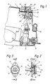
- a locking cylinder 2 is fastened in the outer skin of a motor vehicle door 1, which is biased by a return spring 3 into a neutral key withdrawal (or insertion) position and against the force of this return spring 3 with a key, not shown, starting from the key withdrawal position can be turned right and left.
- a lock nut 5 is coupled in a known manner to the lock cylinder 2 via a coupling which is subject to rotational play, via a rotary rod 4 fastened to the rear side of the lock cylinder 2, which faces away from the keyhole (also not shown).
- the rotary rod 4 is provided in the area which, in the final assembly state shown, lies in the lock nut 5, with driver elements 6 which correspond to driver elements of the lock nut.
- the lock nut 5 is rotatably mounted in a lock carrier plate 7 in the "wet area" of the door interior.
- the lock nut 5 is taken along, so that the associated lock, not shown, is unlocked or locked via a suitable lever connection - only indicated by an extension 5H of the lock nut 5.
- the lock nut 5 is turned back into its neutral position by the return spring 3, the lock nut 5, the lever connection and the lock itself remain in the respective unlocking or locking position.
- the rotary rod 4 is axially extended from the lock cylinder 2 through the lock nut 5 and penetrates an opening 8 in a carrier plate 9 which is formed by the inner door panel facing the interior or passenger compartment of the vehicle is.
- a switch actuation part 10 is rotatably mounted concentrically to the aforementioned opening 8 in a carrier part 11, which also carries two microswitches 12 and is in turn fastened on the carrier plate 9.
- a clip connection is preferably provided between the carrier part 11 and the carrier plate 9. In the delivery state of the vehicle, the door inner panel and thus also the carrier panel 9 and the entire switch arrangement are covered by a door inner panel.
- Both the lock nut 5 and the switch actuating part 10 each have a funnel contour TR on their side facing the locking cylinder 2, which in each case facilitates the insertion of the rotating rod 4 to be positively coupled with both parts when installing the locking cylinder 2 by moving the rotating rod end in the direction the central push-through opening of the lock nut 5 or the switch actuating part 10 centers.
- the switch actuating part 10 is provided on its outer circumference opposite the microswitches 12 in a known manner with nocks NO which are located in different planes and distributed over the circumference as required by the switching points of the microswitches and which correspond to rocker switches SW of the microswitches.
- the switch actuating part 10 is not rotated synchronously with the lock nut 5 from the inside when the unlocked lock is mechanically unlocked, as a result of which, for. B. influencing a controllable by the microswitch 12 mechanical anti-theft device is reliably prevented by the door security.
- the lock nut can be rotated relative to the lock cylinder because of the mentioned free play, but the switch actuation part cannot because of the positive coupling with the rotating rod. It can only be turned with the key in the locking cylinder.
- the opening 8 is sealed by a film 13 inserted between the carrier part 11 and the carrier plate 9; Of course, other sealants, e.g. B. sealing rings made of foam, etc.
- the sealing of the gap between the door and the body is usually the responsibility of a door seal TD. It is also possible to seal between the switch actuating part 10 and the support part 11 - z. B. as a lip seal on the outer circumference or on the outer edge of the funnel contour TR of the switch actuating part 10 - to be provided, in which case the receiving bore of the switch actuating part 10 for the free end of the rotary rod 4 is either designed as a blind hole or in an otherwise suitable manner to the vehicle interior or to the control switches 12 must be sealed off.
- any positive locking elements e.g. B. corresponding square or polygonal cross sections, but also gears can be used.
- a square section 6 ' is shown at the free end of the rotary rod 4.
- FIG. 3 is a sectional view along the section line III-III in FIG. 2, while in FIG. 3 the section plane is indicated in FIG. 2 by a section line II-II -
- a carrier part 11 ' which is provided for direct mounting on the carrier plate 9 shown in FIG. 1 in the region of the opening 8, can advantageously be designed as a compact unit with a switch actuating part 10', a movable contact pin 14 and switching segments 15, 16, which together form at least one control switch 12 '.
- the carrier part 11 ' is provided with a flange and through openings for screws for fastening to the carrier plate 9.
- the switch actuation part 10 here has a driver slot 17 which is arranged concentrically with its axis of rotation and which is brought into engagement with a corresponding end flat cross section 6''of the broken rod 4 indicated in the drawing. It goes without saying that such a rotary coupling can also be used for the switch actuating part 10 shown in FIG.
- the switch segments 15 and 16 to be regarded as fixed contacts of the control switch 12' are inserted flush, while the contact pin 14 - which is to be regarded as the switch contact of the control switch 12 '- is itself fastened in the switch actuating part 10' .
- the same electrical potential of both switching segments - is a single-pole, regardless of the direction of rotation of the locking cylinder or the rotary rod / the switch actuating part 10 'switchable control switch 12' is created
- the second case different electrical potentials or connections of the switching segments - there is a changeover switch 12 'with a neutral central position or the equivalent arrangement of two single-pole pushbutton switches, each of which one is switchable in a certain direction of rotation.
- the switch actuation part 10 ' is fastened in the carrier part 11' by means of a clipped-on cover plate 18 and is biased away from the cover plate 18 by a plate spring 19 onto the switching segments 15 and 16.
- FIGS. 2 and 3 has the advantage over the use of microswitches (FIG. 1) that the switching points of the control switch formed by these and the contact pin can be maintained much more precisely by the spatial arrangement of the switching segments.
- the use of this simplified "integrated" switch form with exposed contacts is only made possible by the inventive arrangement of the control switch outside the at least moist door interior.
- the switch actuating part 10 'and the control switch 12' can also be sealed in this embodiment with respect to the interior of the door by a sealing film glued in between the carrier part 11 'and the carrier plate 9; If necessary, however, a round cord sealing ring or another suitable seal between the carrier part 11 'and the switch actuating part 10' z. B. on the outer circumference of the provided with the driving slot 17, in the support part 11 'rotatably mounted neck-shaped part of the switch actuating part 10'.
- Only one movable contact pin 14 is shown here, which is connected to one of the switching segments 15 or 16 in the case of right or Turning the lock cylinder or the rotary rod 4 counterclockwise makes electrical contact by approx. 40 °. But it can also be provided a second contact pin in the switch actuating part 10 ', the contact pin 14 z. B. diametrically opposite with respect to the axis of rotation of the switch actuating part 10 'and can be connected via its own electrical line. If the locking cylinder can now be rotated beyond the aforementioned 40 ° rotation angle, the two contact pins can be brought into contact with one of the switching segments at the same time with a suitable circumferential expansion of the switching segments, as a result of which a further switching function can be implemented.
- a central locking system could be controlled in the unlocking or locking direction with one contact pin 14 and one of the switching segments 15 or 16 (the switch 12 'would then have the function of a changeover button with a neutral central position), while an additional anti-theft device depends on
- the direction of rotation of the locking cylinder is only switched on or off if at the same time each of the two contact pins is brought into contact with one of the switching segments 15 or 16.
- Such a circuit is of course also possible with the conventional microswitches 12 shown in FIG. 1 by providing suitable switching cams NO on the switch actuating part 10.
Landscapes
- Lock And Its Accessories (AREA)
Applications Claiming Priority (2)
| Application Number | Priority Date | Filing Date | Title |
|---|---|---|---|
| DE4008834A DE4008834C1 (en) | 1990-03-20 | 1990-03-20 | Interrogator for car door lock - has switch trip coupled to cylinder and connected to adjacent control switch |
| DE4008834 | 1990-03-20 |
Publications (2)
| Publication Number | Publication Date |
|---|---|
| EP0447818A1 true EP0447818A1 (fr) | 1991-09-25 |
| EP0447818B1 EP0447818B1 (fr) | 1993-08-11 |
Family
ID=6402583
Family Applications (1)
| Application Number | Title | Priority Date | Filing Date |
|---|---|---|---|
| EP91102379A Expired - Lifetime EP0447818B1 (fr) | 1990-03-20 | 1991-02-20 | Système pour interroger les écarts angulaires d'un cylindre de serrure dans un système de fermeture actionné par clefs |
Country Status (4)
| Country | Link |
|---|---|
| US (1) | US5224364A (fr) |
| EP (1) | EP0447818B1 (fr) |
| JP (1) | JPH0826712B2 (fr) |
| DE (2) | DE4008834C1 (fr) |
Cited By (3)
| Publication number | Priority date | Publication date | Assignee | Title |
|---|---|---|---|---|
| FR2752005A1 (fr) * | 1996-07-30 | 1998-02-06 | Kiekert Ag | Fermeture de portiere de vehicule automobile avec systeme de serrure et systeme de fermeture |
| GB2316436B (en) * | 1996-08-24 | 2001-03-07 | Kiekert Ag | Motor vehicle door lock |
| EP1234934A2 (fr) | 2001-02-24 | 2002-08-28 | Huf Hülsbeck & Fürst GmbH & Co. KG | Ensemble de poignée de porte extérieure, notamment pour véhicule |
Families Citing this family (20)
| Publication number | Priority date | Publication date | Assignee | Title |
|---|---|---|---|---|
| DE4039443C1 (fr) * | 1990-12-11 | 1992-06-25 | Mercedes-Benz Aktiengesellschaft, 7000 Stuttgart, De | |
| DE19600224C1 (de) * | 1996-01-05 | 1997-02-13 | Daimler Benz Ag | Schließeinrichtung für Fahrzeuge, insbesondere für Fahrzeugtüren |
| US5852943A (en) * | 1996-05-06 | 1998-12-29 | Ut Automotive Dearborn, Inc. | Door lock mechanism for an automotive vehicle |
| DE59705398D1 (de) * | 1996-07-04 | 2001-12-20 | Huf Huelsbeck & Fuerst Gmbh | Verschluss für türen, hauben, klappen od. dgl., insbesondere von fahrzeugen, wie kraftfahrzeugen |
| DE19702276B4 (de) * | 1996-07-30 | 2007-01-25 | Kiekert Ag | Kraftfahrzeugtürverschluß mit Schloßsystem und Schließsystem, welcher eine Einrichtung zur Abfrage der Funktionsstellung des Schließzylinders aufweist, die mit Hallsensoren arbeitet |
| DE19702275B4 (de) * | 1996-07-30 | 2007-01-25 | Kiekert Ag | Kraftfahrzeugtürverschluß mit Schloßsystem welcher eine Einrichtung zur Abfrage der Funktionsstellung des Schließzylinders aufweist, die mit Hallsensoren arbeitet |
| DE19702206C2 (de) * | 1996-08-24 | 2000-08-03 | Kiekert Ag | Kraftfahrzeugtürverschluß mit Schloßsystem und Schließsystem, welcher eine Einrichtung zur Abfrage der Funktionsstellungen des Schließzylinders aufweist, die mit Hallsensoren arbeitet |
| US5737948A (en) * | 1996-12-17 | 1998-04-14 | Lefkovits; Jacob | Access control system |
| JP3410372B2 (ja) * | 1998-08-31 | 2003-05-26 | アイシン精機株式会社 | 車両用ドアロック操作システム及び該ドアロック操作システムを備えた車両用ドア |
| DE60021223T2 (de) * | 1999-04-22 | 2006-04-27 | Aisin Seiki K.K., Kariya | Türsystem für Kraftfahrzeuge mit Türschliessvorrichtung und Türaussengriff |
| DE20016108U1 (de) * | 2000-09-16 | 2001-01-18 | Kiekert AG, 42579 Heiligenhaus | Türbetätigungsaggregat für insbesondere Kraftfahrzeuge |
| JP3777968B2 (ja) * | 2000-10-26 | 2006-05-24 | アイシン精機株式会社 | ドアロック装置 |
| DE10056751A1 (de) * | 2000-11-16 | 2002-05-23 | Daimler Chrysler Ag | Türschloß für eine Kraftfahrzeugtür |
| KR100394715B1 (ko) * | 2001-05-16 | 2003-08-14 | 기아자동차주식회사 | 자동차용 도어언록 시스템 |
| DE102005042350A1 (de) * | 2005-09-07 | 2007-03-15 | Huf Hülsbeck & Fürst Gmbh & Co. Kg | Schließzylinder für insbesondere an Fahrzeugen vollziehbare Funktionen |
| CN101512085B (zh) * | 2006-08-26 | 2012-12-05 | 胡夫休尔斯贝克及福尔斯特公司 | 用于操纵在车辆的门或盖板中的锁的装置 |
| US8373550B2 (en) * | 2008-08-20 | 2013-02-12 | Control Solutions LLC | Door assist system controller and method |
| DE102013009112A1 (de) * | 2013-05-29 | 2014-12-04 | Huf Hülsbeck & Fürst Gmbh & Co. Kg | Moduleinheit zum Öffnen- und Schließen von Flügeln |
| JP7028627B2 (ja) * | 2017-12-19 | 2022-03-02 | マツダ株式会社 | 車両用ドアロック装置、及び、その取付方法 |
| CN109676373B (zh) * | 2019-02-26 | 2023-07-04 | 张必葵 | 一种锁具装配机及其锁芯装配机构 |
Citations (3)
| Publication number | Priority date | Publication date | Assignee | Title |
|---|---|---|---|---|
| DE3639043C1 (en) * | 1986-11-14 | 1988-01-28 | Audi Ag | Locking mechanism for motor-vehicle doors |
| DE3717778C2 (fr) * | 1987-05-26 | 1989-03-09 | Bomoro Bocklenberg & Motte Gmbh & Co Kg, 5600 Wuppertal, De | |
| DE3827564C1 (fr) * | 1988-08-13 | 1989-05-11 | Daimler-Benz Aktiengesellschaft, 7000 Stuttgart, De |
Family Cites Families (11)
| Publication number | Priority date | Publication date | Assignee | Title |
|---|---|---|---|---|
| US1395881A (en) * | 1920-07-31 | 1921-11-01 | Wattel Achille Leon Francois | Automobile-locking apparatus |
| US1670043A (en) * | 1924-03-20 | 1928-05-15 | Samuel D Mott | Multiple-control system |
| US1725158A (en) * | 1927-06-20 | 1929-08-20 | Peter C Pinkerton | Automobile locking device |
| US2795127A (en) * | 1954-10-04 | 1957-06-11 | Alex A Gust | Automobile door locking and unlocking means |
| US3000204A (en) * | 1957-08-23 | 1961-09-19 | Lisle W Menzimer | Door control mechanism |
| US2996910A (en) * | 1959-06-15 | 1961-08-22 | Lester C Willis | Door lock system |
| FR2036534A5 (fr) * | 1969-03-24 | 1970-12-24 | Peugeot & Renault | |
| DE2164651A1 (de) * | 1971-12-24 | 1973-06-28 | Leonard Palman | Sicherheitsschloss, insbesondere fuer fahrzeuge |
| DE2720713C2 (de) * | 1977-05-07 | 1983-12-08 | Daimler-Benz Ag, 7000 Stuttgart | Betätigungsvorrichtung für Türschlösser von Kraftfahrzeugen |
| DE3513555A1 (de) * | 1985-04-16 | 1986-11-27 | Bayerische Motoren Werke AG, 8000 München | Schliesseinrichtung fuer eine zentralverriegelungsanlage eines kraftfahrzeuges |
| JPS62101782A (ja) * | 1985-10-30 | 1987-05-12 | 株式会社 大井製作所 | 自動車用ドアロツク制御装置 |
-
1990
- 1990-03-20 DE DE4008834A patent/DE4008834C1/de not_active Expired - Lifetime
-
1991
- 1991-02-20 DE DE9191102379T patent/DE59100267D1/de not_active Expired - Fee Related
- 1991-02-20 EP EP91102379A patent/EP0447818B1/fr not_active Expired - Lifetime
- 1991-03-19 JP JP13070791A patent/JPH0826712B2/ja not_active Expired - Lifetime
- 1991-03-20 US US07/672,315 patent/US5224364A/en not_active Expired - Fee Related
Patent Citations (3)
| Publication number | Priority date | Publication date | Assignee | Title |
|---|---|---|---|---|
| DE3639043C1 (en) * | 1986-11-14 | 1988-01-28 | Audi Ag | Locking mechanism for motor-vehicle doors |
| DE3717778C2 (fr) * | 1987-05-26 | 1989-03-09 | Bomoro Bocklenberg & Motte Gmbh & Co Kg, 5600 Wuppertal, De | |
| DE3827564C1 (fr) * | 1988-08-13 | 1989-05-11 | Daimler-Benz Aktiengesellschaft, 7000 Stuttgart, De |
Cited By (5)
| Publication number | Priority date | Publication date | Assignee | Title |
|---|---|---|---|---|
| FR2752005A1 (fr) * | 1996-07-30 | 1998-02-06 | Kiekert Ag | Fermeture de portiere de vehicule automobile avec systeme de serrure et systeme de fermeture |
| GB2316436B (en) * | 1996-08-24 | 2001-03-07 | Kiekert Ag | Motor vehicle door lock |
| EP1234934A2 (fr) | 2001-02-24 | 2002-08-28 | Huf Hülsbeck & Fürst GmbH & Co. KG | Ensemble de poignée de porte extérieure, notamment pour véhicule |
| DE10109106A1 (de) * | 2001-02-24 | 2002-09-12 | Huf Huelsbeck & Fuerst Gmbh | Türaußengriff-Baugruppe, insbesondere für Fahrzeuge |
| DE10109106B4 (de) * | 2001-02-24 | 2004-02-12 | Huf Hülsbeck & Fürst Gmbh & Co. Kg | Türaußengriff-Baugruppe, insbesondere für Fahrzeuge |
Also Published As
| Publication number | Publication date |
|---|---|
| US5224364A (en) | 1993-07-06 |
| JPH0771147A (ja) | 1995-03-14 |
| JPH0826712B2 (ja) | 1996-03-13 |
| DE4008834C1 (en) | 1991-07-11 |
| EP0447818B1 (fr) | 1993-08-11 |
| DE59100267D1 (de) | 1993-09-16 |
Similar Documents
| Publication | Publication Date | Title |
|---|---|---|
| EP0447818B1 (fr) | Système pour interroger les écarts angulaires d'un cylindre de serrure dans un système de fermeture actionné par clefs | |
| EP1636454B1 (fr) | Barillet electromagnetique | |
| DE102011086609B4 (de) | Antenneneinheit und Türgriffeinrichtung mit derselben | |
| DE202010012379U1 (de) | Stellantrieb für ein Kraftfahrzeug | |
| DE19845723B4 (de) | Verriegelungsvorrichtung für eine Fahrzeugtür | |
| DE102010029446A1 (de) | Stellantrieb für ein Kraftfahrzeug | |
| DE69802271T2 (de) | Lenkstockmodul mit radialem zusammenbau | |
| WO1999001635A2 (fr) | Dispositif permettant de transmettre des mouvements de commande mecaniques et/ou des signaux electriques entre un dispositif d'actionnement et un dispositif d'arret de portiere d'automobile | |
| DE102012211898A1 (de) | Türschließvorrichtung | |
| DE1936734B2 (de) | Betätigungsvorrichtung für ein Türschloß, insbesondere von Kraftfahrzeugen | |
| DE4436172A1 (de) | Elektrische Verbindungseinrichtung | |
| EP0235350B1 (fr) | Interrupteur, en particulier pour véhicule | |
| DE102014102300A1 (de) | Türverriegelungs-/Entriegelungsbetätigungsvorrichtung und Schließzylindereinbauteile für Fahrzeugtür | |
| DE3516732C1 (de) | Kombinierte Zentralverriegelungs- und Sicherungsanlage für Verschlüsse an einem Kraftfahrzeug | |
| DE102019130176B4 (de) | Steckverbinderteil mit einer Rasteinrichtung | |
| DE202021100348U1 (de) | 3-Position-Betätigungsmechanismus | |
| EP0710970B1 (fr) | Dispositif d'actionnement manuel verrouillable pour la mise en marche ou arrêt d'appareils interrupteurs électriques blindés en particulier des disjoncteurs | |
| EP1923966A2 (fr) | Prise | |
| AT398108B (de) | Schlossplatte | |
| DE9203143U1 (de) | Elektrische Schaltvorrichtung | |
| DE10261505B4 (de) | Verriegelungsvorrichtung für eine Fahrzeugtür | |
| DE102015220001B4 (de) | Zündanlassschalter, Montageeinheit sowie Kraftfahrzeug mit einer solchen Montageeinheit | |
| DE3743557C2 (de) | Befestigungssystem für Gerätesockel | |
| DE102021000442B4 (de) | Türgriff zur Türschlossbetätigung, insbesondere für ein Fahrzeug | |
| DE19861199B4 (de) | Verriegelungsvorrichtung für eine Fahrzeugtür |
Legal Events
| Date | Code | Title | Description |
|---|---|---|---|
| PUAI | Public reference made under article 153(3) epc to a published international application that has entered the european phase |
Free format text: ORIGINAL CODE: 0009012 |
|
| 17P | Request for examination filed |
Effective date: 19910720 |
|
| AK | Designated contracting states |
Kind code of ref document: A1 Designated state(s): DE FR GB IT SE |
|
| 17Q | First examination report despatched |
Effective date: 19930202 |
|
| ITF | It: translation for a ep patent filed | ||
| GRAA | (expected) grant |
Free format text: ORIGINAL CODE: 0009210 |
|
| AK | Designated contracting states |
Kind code of ref document: B1 Designated state(s): DE FR GB IT SE |
|
| REF | Corresponds to: |
Ref document number: 59100267 Country of ref document: DE Date of ref document: 19930916 |
|
| GBT | Gb: translation of ep patent filed (gb section 77(6)(a)/1977) |
Effective date: 19930915 |
|
| ET | Fr: translation filed | ||
| ITTA | It: last paid annual fee | ||
| PLBE | No opposition filed within time limit |
Free format text: ORIGINAL CODE: 0009261 |
|
| STAA | Information on the status of an ep patent application or granted ep patent |
Free format text: STATUS: NO OPPOSITION FILED WITHIN TIME LIMIT |
|
| 26N | No opposition filed | ||
| EAL | Se: european patent in force in sweden |
Ref document number: 91102379.4 |
|
| REG | Reference to a national code |
Ref country code: FR Ref legal event code: TP |
|
| REG | Reference to a national code |
Ref country code: GB Ref legal event code: 732E |
|
| REG | Reference to a national code |
Ref country code: GB Ref legal event code: 732E |
|
| PGFP | Annual fee paid to national office [announced via postgrant information from national office to epo] |
Ref country code: GB Payment date: 20000214 Year of fee payment: 10 |
|
| PGFP | Annual fee paid to national office [announced via postgrant information from national office to epo] |
Ref country code: FR Payment date: 20000222 Year of fee payment: 10 |
|
| PGFP | Annual fee paid to national office [announced via postgrant information from national office to epo] |
Ref country code: SE Payment date: 20000223 Year of fee payment: 10 |
|
| PGFP | Annual fee paid to national office [announced via postgrant information from national office to epo] |
Ref country code: DE Payment date: 20000420 Year of fee payment: 10 |
|
| PG25 | Lapsed in a contracting state [announced via postgrant information from national office to epo] |
Ref country code: GB Free format text: LAPSE BECAUSE OF NON-PAYMENT OF DUE FEES Effective date: 20010220 |
|
| PG25 | Lapsed in a contracting state [announced via postgrant information from national office to epo] |
Ref country code: SE Free format text: LAPSE BECAUSE OF NON-PAYMENT OF DUE FEES Effective date: 20010221 |
|
| EUG | Se: european patent has lapsed |
Ref document number: 91102379.4 |
|
| GBPC | Gb: european patent ceased through non-payment of renewal fee |
Effective date: 20010220 |
|
| PG25 | Lapsed in a contracting state [announced via postgrant information from national office to epo] |
Ref country code: FR Free format text: LAPSE BECAUSE OF NON-PAYMENT OF DUE FEES Effective date: 20011031 |
|
| REG | Reference to a national code |
Ref country code: FR Ref legal event code: ST |
|
| PG25 | Lapsed in a contracting state [announced via postgrant information from national office to epo] |
Ref country code: DE Free format text: LAPSE BECAUSE OF NON-PAYMENT OF DUE FEES Effective date: 20011201 |
|
| PG25 | Lapsed in a contracting state [announced via postgrant information from national office to epo] |
Ref country code: IT Free format text: LAPSE BECAUSE OF NON-PAYMENT OF DUE FEES;WARNING: LAPSES OF ITALIAN PATENTS WITH EFFECTIVE DATE BEFORE 2007 MAY HAVE OCCURRED AT ANY TIME BEFORE 2007. THE CORRECT EFFECTIVE DATE MAY BE DIFFERENT FROM THE ONE RECORDED. Effective date: 20050220 |