EP0447841A2 - Méthode pour établir des liaisons virtuelles dans un système de commutation travaillant selon le mode de transfert asynchrone (ATM) - Google Patents
Méthode pour établir des liaisons virtuelles dans un système de commutation travaillant selon le mode de transfert asynchrone (ATM) Download PDFInfo
- Publication number
- EP0447841A2 EP0447841A2 EP91102853A EP91102853A EP0447841A2 EP 0447841 A2 EP0447841 A2 EP 0447841A2 EP 91102853 A EP91102853 A EP 91102853A EP 91102853 A EP91102853 A EP 91102853A EP 0447841 A2 EP0447841 A2 EP 0447841A2
- Authority
- EP
- European Patent Office
- Prior art keywords
- bit rate
- atm
- transmission
- connection
- atm intermediate
- Prior art date
- Legal status (The legal status is an assumption and is not a legal conclusion. Google has not performed a legal analysis and makes no representation as to the accuracy of the status listed.)
- Granted
Links
- 238000000034 method Methods 0.000 title claims description 20
- 238000012546 transfer Methods 0.000 title claims description 6
- 230000005540 biological transmission Effects 0.000 claims abstract description 85
- 230000015654 memory Effects 0.000 claims abstract description 61
- 230000008878 coupling Effects 0.000 claims abstract description 16
- 238000010168 coupling process Methods 0.000 claims abstract description 16
- 238000005859 coupling reaction Methods 0.000 claims abstract description 16
- 239000011159 matrix material Substances 0.000 abstract description 16
- 238000004891 communication Methods 0.000 description 4
- 238000012545 processing Methods 0.000 description 2
- 230000011664 signaling Effects 0.000 description 2
- VCGRFBXVSFAGGA-UHFFFAOYSA-N (1,1-dioxo-1,4-thiazinan-4-yl)-[6-[[3-(4-fluorophenyl)-5-methyl-1,2-oxazol-4-yl]methoxy]pyridin-3-yl]methanone Chemical compound CC=1ON=C(C=2C=CC(F)=CC=2)C=1COC(N=C1)=CC=C1C(=O)N1CCS(=O)(=O)CC1 VCGRFBXVSFAGGA-UHFFFAOYSA-N 0.000 description 1
- 230000006870 function Effects 0.000 description 1
- 230000000977 initiatory effect Effects 0.000 description 1
- 230000008092 positive effect Effects 0.000 description 1
- 230000000750 progressive effect Effects 0.000 description 1
- 238000012360 testing method Methods 0.000 description 1
- 230000001960 triggered effect Effects 0.000 description 1
Images
Classifications
-
- H—ELECTRICITY
- H04—ELECTRIC COMMUNICATION TECHNIQUE
- H04L—TRANSMISSION OF DIGITAL INFORMATION, e.g. TELEGRAPHIC COMMUNICATION
- H04L45/00—Routing or path finding of packets in data switching networks
- H04L45/02—Topology update or discovery
- H04L45/10—Routing in connection-oriented networks, e.g. X.25 or ATM
-
- H—ELECTRICITY
- H04—ELECTRIC COMMUNICATION TECHNIQUE
- H04L—TRANSMISSION OF DIGITAL INFORMATION, e.g. TELEGRAPHIC COMMUNICATION
- H04L45/00—Routing or path finding of packets in data switching networks
- H04L45/20—Hop count for routing purposes, e.g. TTL
Definitions
- the invention relates to a method for setting up virtual connections in switching devices operating according to an asynchronous transfer mode according to the preamble of patent claim 1.
- Methods of this type are already known from the magazine INTERNATIONAL JOURNAL OF DIGITAL AND ANALOG CABLED SYSTEMS, VOL. 1, article by K.A. Lutz on pages 237-243 (1988) and through the conference paper from the International Switching Symposium, 15-20. March 1987, Proceedings, Phoenix, USA, 3 (1987), pages 602-608.
- Methods of the known type are used to set up virtual connections for packet switching. For this purpose, routes via connecting lines and ATM (ASYNCHRONOUS TRANSFER MODE) coupling fields are searched for, selected and defined. Within an ATM switching matrix, routes are established via ATM switching elements and via ATM intermediate lines.
- route search When searching, selecting and specifying routes (route search) for new virtual connections to be set up, it is important that routes already occupied by virtual connections may only be used for further virtual connections to the extent that free transmission capacity is still available on these routes is.
- This still free transmission capacity, which is available for setting up new virtual connections can already equal, for example, the difference between the total transmission capacity of an intermediate line and that of virtual connections set up via it used transmission capacity. The latter can be the sum of all peak bit rates of the virtual connections in question, for example.
- the invention is aimed at simplifying the very common procedure of searching for a route in the case of methods of the type specified at the outset. If a size comparison of the type mentioned above is now carried out for each route search, this results in particularly tough requirements for corresponding processing facilities, because the processes for setting up new virtual connections, on the one hand, are relatively frequent per unit of time and, on the other hand, not too should take a long time. Waiting time problems when establishing a connection are bothersome and undesirable.
- the processing operations are to be designed in such a way that all operations which have to be carried out immediately before and for each establishment of a new virtual connection are simplified as much as possible.
- the invention solves this problem in a method according to the preamble of claim 1 by the method features specified in the characterizing part of this claim.
- the invention makes the size comparisons between available transmission capacities and required transmission capacities reduced to simple one-bit comparisons. This considerably simplifies the search for paths for new virtual connections to be set up, which is of particular importance for virtual connections via ATM switching networks with several switching stages and accordingly via different groups of ATM intermediate lines. These groups are located at different points between the successive coupling stages in the ATM switching matrix. Connection bit rate classes are now formed for this.
- a route search uses the different storage elements corresponding to this connection bit rate class, starting from the connection bit rate class relevant for a new virtual connection to be established, and uses simple one-bit comparisons to determine the ATM intermediate lines that can be used for the new virtual connection to be set up .
- a switching device is shown as an embodiment in which the invention is applied. Of this switching device, only components serving to understand the present invention are listed.
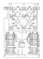
- An ATM switching matrix K (hereinafter simply referred to as "switching matrix") of an ATM switching center contains three switching stages K1 to K3 ATM switching elements v11 to v3n (hereinafter only referred to as “switching element” or “switching elements”), which use intermediate lines z111 to zm3n are connected to each other in the manner shown.
- ATM switching centers in communication facilities with asynchronous transfer mode are already known from extensive specialist literature, for which reference is made to some exemplary examples: "International Zurich Seminar on Digital Communications” (March 1986) with the publication “New Directions in Communications” (section A3.1 to A3.8, by JB Turner); German Offenlegungsschrift 3,732,937; European patent application 89102172.7; Journal “Kommunikationstechnik, Elektronik", Berlin, 39 (1989) 1, pages 3 and 4.
- the switching device shown in the drawing is therefore a circuit arrangement for communication devices with asynchronous transfer mode.
- Virtual connections are set up via the multi-stage switching matrix K.
- ATM intermediate lines z111 to zm3n lead from coupling stage to coupling stage. They connect the switching multiples v11 to v3n of the three successive switching stages K1 to K3 with each other.
- connection-specific routes are sought, selected and defined.
- connection path this can be a galvanically or time-multiplexed path
- Connections are of the type that they transmit information in the form of message packets (cells), that these packets (cells) are identified on the basis of a header, and that all packets (cells) of a virtual connection each use the same route selected during setup via network and transmission paths in the network.
- Message packets or data packets to be transmitted via virtual connections are transmitted in packets, with further data packets, namely other virtual connections, being transmitted via the relevant connection paths, for example transmission channels of transmission systems and intermediate lines, between the data packets to be transmitted for the virtual connection in question.
- relevant connection paths for example transmission channels of transmission systems and intermediate lines, between the data packets to be transmitted for the virtual connection in question.
- virtual connections are precisely defined in terms of path. Appropriate route search and selection devices are used in the relevant switching centers for this purpose.
- connection-specific bit rate limit values are set for virtual connections in an ATM switching device by storing corresponding data. These bit rate limits can e.g. the peak bit rates of the virtual connections in question. If a subscriber wishes to set up a new virtual connection, he indicates the top bit rate at which he intends to send (messages, data and the like). This peak bit rate must never be exceeded by him when sending data packets.
- a first ATM switching center In which data packets sent by the subscriber in question arrive, it is continuously monitored whether the incoming ATM message stream with regard to the peak bit rate complies with or exceeds the rate values announced by the subscriber concerned; if the limit is exceeded, appropriate countermeasures are initiated in the exchange. This can consist of parts of the message packets being suppressed, i.e. not transmitted at all or garbled, and / or that corresponding signaling is transmitted to the subscriber in question or that a virtual connection is forcibly interrupted.
- a corresponding countermeasure can also consist in the fact that corresponding packets are initially only marked and only discarded if the load situation in the network actually requires this. This countermeasure means that there can also be exceptions to the above prohibition of exceeding that can be permitted if the network load situation allows this.
- an average bit rate (average over a longer time, for example over a time interval of a few) can be used in addition to the peak bit rate Minutes). Both the peak bit rate and the mean bit rate can be used together as a criterion.
- European patent application 90122430.3 In this context, reference is made to European patent application 90122430.3.
- connection-specific bit rate limit values are set for virtual connections in an ATM switching device by storing corresponding data (peak bit rate and / or average bit rate).
- the other intermediate lines are out of the question, because they are already seen from the switching matrix structure for the relevant one virtual connection are obviously not suitable.
- the intermediate lines that are suitable for setting up a new virtual connection all are now checked to determine whether each of them still has the required transmission capacity. It is now assumed that this transmission capacity is no longer available on the ATM intermediate lines z111 and z232 in the example mentioned. In this case, the new virtual connection cannot be set up via the ATM intermediate lines z111 / z132 / z112 / z232. However, the desired virtual connection can be set up via the ATM intermediate lines z11m and zm32. In this respect it can be seen that a coincidence condition with regard to the transmission capacity still available must be fulfilled. This coincidence condition is essential for the route search. It must therefore be checked whether this coincidence condition is met in each case.
- an ATM switching device contains only a three-stage switching matrix. The same applies, however, to four-stage and additional multi-stage switching fields.
- the drawing now shows, among other things, an ATM intermediate line occupancy memory, which consists of the memory parts x1 to xk and y to yn.
- this occupancy memory With the help of this occupancy memory, the free bit rate transmission capacities still available on the individual intermediate line for the ATM intermediate lines of the switching matrix K are stored. These stored capacities are used for the test already described above, in which the permissibility of setting up new virtual connections with respect to each of the ATM intermediate lines in question for them is based on the bit rate limit values defined for the respective new virtual connections and on the basis of the free bit rate transmission capacity still available is checked on the relevant ATM intermediate lines.
- bit rate limit values freely selected by the subscriber or determined by the respective end device arrive through the subscriber signaling (dialing), these are initially assigned to size ranges of the bit rate limit values. This affects both the middle bit rate and the peak bit rate.
- the relationship between the average bit rate and the peak bit rate is also not fixed. Connection requests can be specified for which the subscriber concerned wishes to send very continuously. In this case, the peak bit rate specified by him is not at all or only slightly higher than the average bit rate specified by him. In the opposite case, there may also be connection requests in which a subscriber only intends to send very sporadically while a virtual connection desired by him exists.
- bit rate limit values specified by the participants are now assigned to defined size ranges of the bit rate values. These size ranges concern both the limit values of the average bit rate and the limit values of the peak bit rate.
- connection bit rate classes are now formed, which are characterized by different size ranges of the bit rate limit values.
- a connection bit rate class is by one Size range in terms of the average bit rate and characterized by a different size range in terms of the peak bit rate.
- the different connection bit rate classes can be characterized in part by the same size ranges with regard to the average bit rate and by different size ranges with regard to the peak bit rate - and vice versa.
- connection bit rate classes which differ from one another in the manner described above by the size ranges of the bit rate limit values are expediently numbered.
- the numbering of a connection bit rate class thus defines the respective size range of the bit rate limit with regard to the medium bit rate and the size range of the bit rate limit with regard to the peak bit rate.
- a subscriber wishes to establish a virtual connection at the subscriber station T, in addition to the usual dialing information, he also issues the bit rate limit values with regard to the average bit rate and with regard to the peak bit rate to the relevant exchange.
- These limits can e.g. are recorded in a subscriber line circuit R and are forwarded from here to a central processor P, which controls the establishment of the virtual connections individually for the connection and, for this purpose, records the two bit rate limit values mentioned for each desired virtual connection and initially stores them.
- the ATM intermediate lines each have a certain maximum transmission capacity. Due to virtual connections already set up via an ATM intermediate line, part of the transmission capacity of the relevant ATM intermediate line has already been used. When setting up a new virtual connection, only the remaining free transmission capacity can then be used. So only this is still for new virtual ones to be set up Connection available. This applies in general, that is, taking peak bit rates and / or medium bit rates into account.
- the ATM intermediate line occupancy memory which is hereinafter simply referred to as "route search memory" is used to record the transmission capacities free per ATM intermediate line in transmission bit rate classes with corresponding transmission bit rate limit values.
- the ATM intermediate lines in the switching matrix K form ATM intermediate line groups.
- An ATM intermediate line group always starts from or leads to a coupling element.
- Such an ATM intermediate line group consists, for example, of the ATM intermediate lines z111 to z11m. It starts from the coupling element v11.
- Another ATM intermediate line group consists, for example, of the ATM intermediate lines z132 to zm32. It leads to the ATM coupling element v32. The same applies to all other ATM intermediate lines in the switching matrix K.
- ATM connecting lines or corresponding subscriber lines are connected to the coupling elements v31 to v3n in a manner known per se. These lead to other ATM exchanges. Only two such ATM connecting lines g1 and g2 are shown.
- the route search memory is now per ATM intermediate group, e.g. z111 to z11m, a family of memory element rows, e.g. x11 to x18.
- One row of memory elements each, e.g. x11, is assigned to one of the transmission bit rate classes.
- the size of this group therefore does not depend on the number of ATM intermediate lines in an ATM intermediate line group, but rather on the number of transmission bit rate classes that are provided at all.
- the memory element rows x11 to xk8 and y11 to yn8 are divided into columns 111 to 11m and 131 to m31.
- One storage element (storage space) is part of a storage element row and at the same time also belongs to a specific column, for example 111.
- each row of memory elements e.g. x11
- the individual storage elements are attached to the respective ATM coupling element, e.g. v11, connected ATM intermediate lines, e.g. z111 to z11m, individually assigned.
- These storage elements are binary signifiable, i.e. they can assume the logical value zero and the logical value one. As a result, they indicate the availability of transmission capacities available on these ATM intermediate lines with regard to the respective transmission bit rate class. This may be signified by the fact that the respective storage element has the logical value one. It shows for the assigned ATM intermediate line, e.g. z111, which yes z. B. column 111 is assigned to indicate that transmission capacity for the respective transmission bit rate class is still available on this ATM intermediate line.
- one row of memory elements corresponds to one transmission bit rate class.
- This bit rate class can - as has also already been explained above - be characterized by two bit rate limit values (from the above size ranges), one of which relates to the mean bit rate and one to the peak bit rate.
- the signification thus indicates for a certain ATM intermediate line (this corresponds to a column) whether transmission capacity is still available with this ATM intermediate line with regard to the respective transmission bit rate class, which is characterized by certain size ranges of the bit rate limit values, whereby these bit rate limit values (as already stated) relate on the one hand to the average bit rate and on the other hand to the peak bit rate.
- this job contains not only the destination information (for example subscriber number) but also information about the desired average bit rate and the peak bit rate.
- the desired virtual connection is assigned to the size ranges relevant to it (in terms of average bit rate and peak bit rate) in accordance with the bit rate limit values; the desired connection is accordingly assigned to a specific connection bit rate class.
- the above-mentioned information is fed from the subscriber line circuit R to a processor P, which among other things makes these assignments.
- This processor also receives the destination information (dialing information) on the basis of which it initiates the establishment of the desired virtual connection via an interface device E in the ATM switching matrix. This is done in a manner known per se. However, when searching for the path itself, the processor proceeds in the manner according to the invention.
- the destination information e.g. long-distance traffic number plus area code plus subscriber number
- a virtual connection must be set up via the coupling element v32.
- the dialing subscriber is the subscriber at subscriber station T.
- the desired virtual connection must therefore be set up using the coupling element v11, among other things.
- the intermediate line groups z111 to z11m and z132 to zm32 can be used for this.
- the processor sends information about this to the route search device L, which has the task of searching, selecting and specifying a suitable free route.
- the path search device L controls the memory parts x1 and y1 with the aid of its reading devices Lx and Ly.
- the processor also informs the reading device L of the bit rate class which is the decisive one for the desired virtual connection.
- the path search device L now uses its reading devices Lx and Ly within the memory parts x1 and y2 to drive those memory element rows within these memory parts that are assigned to the bit rate class.
- the path search device L now searches within of the two memory element rows under those ATM intermediate lines one that are coincidentally signed by a logical 1 with regard to the sequence of the columns 111 to 11m and 131 to m32.
- the two logical values mentioned are also interchangeable.
- the two reading devices Lx and Ly therefore read the contents of the individual memory elements progressively from left to right column by column in the relevant two memory rows, and at the same time memory element by memory element in each of the two memory element rows.
- Such a search sequence is called one with a fixed zero position. However, one with a progressive or also randomly or otherwise changing zero position can also be used.
- the path search device L receives a logical one at the same time via its two reading devices Lx and Ly, it can be recognized by this that the respective two ATM intermediate lines still have transmission capacity for the desired bit rate class and thus for the establishment of a new virtual connection is available.
- the relevant bit rate class ensures that an average bit rate and a peak bit rate corresponding to the size ranges of the bit rate limit values can be transmitted via the relevant virtual connection. Based on the bit rate limit value or the relevant bit rate limit values that are relevant for the new virtual connection to be set up (expressed by the relevant bit rate class), a line of memory elements is searched for, whose assigned bit rate class transmits these two bit rate limit values and thus the desired one Bit rate class corresponds to the transmission capacity required for the new virtual connection.
- One of the intermediate lines whose storage elements are signed is selected within the relevant storage element row. This takes place according to a selection mode provided for the route search and mentioned above. This can provide that a selection with a fixed zero point and constant search order comes into play. However, other selection modes can also be used, for example with a non-fixed zero position and / or with a non-fixed search sequence.
- ATM intermediate lines are selected in accordance with the memory element rows in question in the various switching stage-unequal ATM intermediate line groups depending on the fact that within these memory element lines there is a coincidence with regard to their corresponding memory elements.
- Corresponding storage elements are those that are in columns of the same name, e.g. 112 and 231.
- connection bit rate classes and the transmission bit rate classes can also be specified according to one or more limit values instead of according to two limit values (average bit rate and peak bit rate).
- each memory section e.g. x1, y1
- connection bit rate classes e.g. x1, y1
- transmission bit rate classes eight different size ranges with regard to the peak bit rates and four different size ranges with regard to the average bit rates.
- the functioning of the processor P includes i.a. also writing the signatures into the individual memory elements of the memory element rows for each of the ATM intermediate lines.
- the available transmission capacity available for new virtual connections is determined on an ATM intermediate line based on the current load condition.
- the storage element for the respective ATM intermediate line is signed in those storage element rows which correspond to transmission bit rate classes with the determined transmission capacity and smaller transmission capacity and which are assigned corresponding transmission bit rate limit values. So e.g. If the still free transmission capacity on the ATM intermediate line z112 is determined, in connection with this the writing device P1 is initially set to the memory part (x1) to which the ATM intermediate line z112 is assigned.
- the writing device P1 If the still free transmission capacity, that is to say available for new virtual connections, has been determined with respect to the ATM intermediate line z112, the writing device P1 writes partly logical zeros and partly logical ones into the column 112 corresponding to this ATM intermediate line z112. In this case, logic ones are written into the memory elements of all those memory element rows, to which transmission bit rate classes are assigned, for which sufficient transmission capacity is still available and available on the ATM intermediate line z112. This is explained in more detail below.
- the processor forms and stores in a further memory area for each ATM intermediate line, on the one hand, the sum of the average bit rates of these connections and, on the other hand, a product sum in which the individual products each consist of the average bit rate and the difference between the peak bit rate and the average bit rate of one of the virtual connections is formed, ie the products are formed individually for each connection.
- This special memory area can, for example, be part of a column, for example 112, in a memory part, for example x1. This special memory area will therefore be assigned to the ATM intermediate line z112.
- the processor P When a new virtual connection is set up and when a virtual connection is set up, the processor P forms the sum and the product sum again. This can be done by using the average bit rate and the product corresponding to the virtual connection in each case changing the occupancy situation to increase or decrease the said sum and the mentioned product sum, i.e. to bring it up to date.
- the central processor determines, for each ATM intermediate line, on the basis of the average bit rates and the peak bit rates of the virtual connections already set up via this intermediate line, based on the average bit rate and peak bit rate of each of the transmission bit rate classes, whether at least one new virtual connection in each case the connection bit rate class corresponding to the respective transmission bit rate class may be set up.
- the processor therefore calculates the options for virtual connections one after the other for each ATM intermediate line in which something has changed in the occupancy situation (i.e. not only when a new virtual connection is set up, but also in the corresponding manner when each such connection is triggered) the different bit rate classes. In doing so, he uses the average bit rate and the peak bit rate of each of the virtual connections already set up via this ATM intermediate line. For this purpose, he expediently uses the sum already formed and the product sum. Starting from medium The processor calculates the bit rate and peak rate of each of the possible transmission bit rate classes as to whether at least one new virtual connection of the bit rate class corresponding to the respective transmission bit rate class may be set up with regard to the transmission capacity still available.
- the processor uses both the named product sum and the stated sum of the average bit rates for the virtual connections that have been set up and adds the corresponding product and the corresponding mean bit rate for a virtual connection of one of the various to the product sum and the sum of the average bit rates Bit rate classes.
- the processor therefore forms a product sum and a sum of the average bit rates for the virtual connections set up and for a virtual connection of one of the different bit rate classes.
- the processor handles this for each bit rate class. It then forms a square root value from the product sum obtained in this way and multiplies it by an enlargement factor. Then he adds the sum of the average bit rates to form a comparison value, which is the result of this addition.
- this ATM intermediate line is signed in the memory line corresponding to the respective transmission bit rate class, ie a logical one is written. In the other case, a logical zero is written.
- comparator V This serves to carry out the coincidence check already described. With its help it is determined that corresponding intermediate lines are coincidentally signed.
- Boundary conditions here are that a) an ATM line with a gross transport capacity (“gross” means 150 Mbit / s is operated, b) the peak bit rates of the virtual connections that are routed via this ATM line do not exceed 2 Mbit / s, and c) the ratio of the average bit rate to the peak bit rate each of the connections is between 0.1 and 0.9.
- gross gross transport capacity
- the switching device described above can also be modified such that, on the one hand, instead of an ATM intermediate line occupancy memory (route search memory) for the ATM intermediate line groups, a number of ATM intermediate line occupancy memories corresponding to the number of ATM intermediate line groups can be provided which can be controlled in parallel in the route search described above, and on the other hand the functions of the route search device L described above can also be carried out by the processor P.
- route search memory route search memory
Landscapes
- Engineering & Computer Science (AREA)
- Computer Networks & Wireless Communication (AREA)
- Signal Processing (AREA)
- Data Exchanges In Wide-Area Networks (AREA)
- Exchange Systems With Centralized Control (AREA)
Applications Claiming Priority (2)
| Application Number | Priority Date | Filing Date | Title |
|---|---|---|---|
| DE4009423 | 1990-03-23 | ||
| DE4009423 | 1990-03-23 |
Publications (3)
| Publication Number | Publication Date |
|---|---|
| EP0447841A2 true EP0447841A2 (fr) | 1991-09-25 |
| EP0447841A3 EP0447841A3 (en) | 1992-06-17 |
| EP0447841B1 EP0447841B1 (fr) | 1995-09-13 |
Family
ID=6402944
Family Applications (1)
| Application Number | Title | Priority Date | Filing Date |
|---|---|---|---|
| EP91102853A Expired - Lifetime EP0447841B1 (fr) | 1990-03-23 | 1991-02-26 | Méthode pour établir des liaisons virtuelles dans un système de commutation travaillant selon le mode de transfert asynchrone (ATM) |
Country Status (5)
| Country | Link |
|---|---|
| US (1) | US5216669A (fr) |
| EP (1) | EP0447841B1 (fr) |
| AT (1) | ATE127988T1 (fr) |
| CA (1) | CA2038743A1 (fr) |
| DE (1) | DE59106450D1 (fr) |
Cited By (3)
| Publication number | Priority date | Publication date | Assignee | Title |
|---|---|---|---|---|
| EP0575655A1 (fr) * | 1992-06-25 | 1993-12-29 | Siemens Aktiengesellschaft | Méthode pour établir des connexions virtuelles |
| WO1994026042A1 (fr) * | 1993-05-03 | 1994-11-10 | Telefonaktiebolaget Lm Ericsson | Procede et systeme de selection de liaison libre |
| DE19907923A1 (de) * | 1999-02-24 | 2000-11-23 | Siemens Ag | Verfahren zum Ermitteln eines Verbindungsweges in einem Kommunikationsnetz zwischen zwei benachbarten Netzknoten |
Families Citing this family (59)
| Publication number | Priority date | Publication date | Assignee | Title |
|---|---|---|---|---|
| EP0447769A3 (en) * | 1990-03-12 | 1994-12-21 | Sel Alcatel Ag | Method and circuit arrangement for managing uniform unities and switching element |
| US5402426A (en) * | 1992-04-23 | 1995-03-28 | Siemens Aktiengesellschaft | Method and arrangement for checking the observance of prescribed transmission bit rates in an ATM switching equipment |
| ATE309658T1 (de) * | 1992-07-20 | 2005-11-15 | Siemens Ag | Atm-kommunikationssystem |
| US5446726A (en) * | 1993-10-20 | 1995-08-29 | Lsi Logic Corporation | Error detection and correction apparatus for an asynchronous transfer mode (ATM) network device |
| US5708659A (en) * | 1993-10-20 | 1998-01-13 | Lsi Logic Corporation | Method for hashing in a packet network switching system |
| US5802287A (en) * | 1993-10-20 | 1998-09-01 | Lsi Logic Corporation | Single chip universal protocol multi-function ATM network interface |
| US5926482A (en) | 1994-05-05 | 1999-07-20 | Sprint Communications Co. L.P. | Telecommunications apparatus, system, and method with an enhanced signal transfer point |
| US6031840A (en) * | 1995-12-07 | 2000-02-29 | Sprint Communications Co. L.P. | Telecommunications system |
| US6430195B1 (en) | 1994-05-05 | 2002-08-06 | Sprint Communications Company L.P. | Broadband telecommunications system interface |
| US6181703B1 (en) * | 1995-09-08 | 2001-01-30 | Sprint Communications Company L. P. | System for managing telecommunications |
| RU2138919C1 (ru) | 1994-05-05 | 1999-09-27 | Спринт Комьюникейшнз Компани Л.П. | Способ, система и устройство управления телефонной связью |
| US6172977B1 (en) * | 1994-05-05 | 2001-01-09 | Sprint Communications Company, L. P. | ATM direct access line system |
| US6314103B1 (en) | 1994-05-05 | 2001-11-06 | Sprint Communications Company, L.P. | System and method for allocating bandwidth for a call |
| US6023474A (en) * | 1996-11-22 | 2000-02-08 | Sprint Communications C.O.L.P. | Broadband telecommunications system interface |
| US5920562A (en) * | 1996-11-22 | 1999-07-06 | Sprint Communications Co. L.P. | Systems and methods for providing enhanced services for telecommunication call |
| US5991301A (en) * | 1994-05-05 | 1999-11-23 | Sprint Communications Co. L.P. | Broadband telecommunications system |
| US6633561B2 (en) | 1994-05-05 | 2003-10-14 | Sprint Communications Company, L.P. | Method, system and apparatus for telecommunications control |
| US5818511A (en) * | 1994-05-27 | 1998-10-06 | Bell Atlantic | Full service network |
| US5608447A (en) * | 1994-05-27 | 1997-03-04 | Bell Atlantic | Full service network |
| US5826102A (en) * | 1994-12-22 | 1998-10-20 | Bell Atlantic Network Services, Inc. | Network arrangement for development delivery and presentation of multimedia applications using timelines to integrate multimedia objects and program objects |
| US5659793A (en) * | 1994-12-22 | 1997-08-19 | Bell Atlantic Video Services, Inc. | Authoring tools for multimedia application development and network delivery |
| US5764626A (en) * | 1995-11-17 | 1998-06-09 | Telecommunications Techniques Corporation | Rate-matched cell identification and modification, replacement, or insertion for test and measurement of ATM network virtual connections |
| US5812528A (en) * | 1995-11-17 | 1998-09-22 | Telecommunications Techniques Corporation | Measuring round trip time in ATM network virtual connections |
| US5699346A (en) * | 1995-11-17 | 1997-12-16 | Telecommunications Techniques Corporation | Measuring burst rate and burst size in ATM network virtual connections |
| US5761191A (en) * | 1995-11-28 | 1998-06-02 | Telecommunications Techniques Corporation | Statistics collection for ATM networks |
| AU2257097A (en) * | 1996-02-02 | 1997-08-22 | Sprint Communications Company, L.P. | Atm gateway system |
| US5826014A (en) * | 1996-02-06 | 1998-10-20 | Network Engineering Software | Firewall system for protecting network elements connected to a public network |
| US5870550A (en) * | 1996-02-26 | 1999-02-09 | Network Engineering Software | Web server employing multi-homed, moldular framework |
| US5898830A (en) * | 1996-10-17 | 1999-04-27 | Network Engineering Software | Firewall providing enhanced network security and user transparency |
| US8117298B1 (en) | 1996-02-26 | 2012-02-14 | Graphon Corporation | Multi-homed web server |
| US5940393A (en) * | 1996-05-28 | 1999-08-17 | Sprint Communications Co. L.P. | Telecommunications system with a connection processing system |
| US5959993A (en) * | 1996-09-13 | 1999-09-28 | Lsi Logic Corporation | Scheduler design for ATM switches, and its implementation in a distributed shared memory architecture |
| US5831980A (en) * | 1996-09-13 | 1998-11-03 | Lsi Logic Corporation | Shared memory fabric architecture for very high speed ATM switches |
| US6002689A (en) * | 1996-11-22 | 1999-12-14 | Sprint Communications Co. L.P. | System and method for interfacing a local communication device |
| KR100459306B1 (ko) | 1996-11-22 | 2004-12-03 | 스프린트 커뮤니케이숀스 컴파니 리미티드 파트너쉽 | 원격통신 네트워크에서 호출을 전송하기 위한 시스템 및 방법 |
| US6014378A (en) * | 1996-11-22 | 2000-01-11 | Sprint Communications Company, L.P. | Telecommunications tandem system for circuit-based traffic |
| US6115380A (en) * | 1996-11-22 | 2000-09-05 | Sprint Communications Co., L.P. | Broadband telecommunications system |
| DE19649649A1 (de) * | 1996-11-29 | 1998-06-04 | Siemens Ag | Verfahren zum statistischen Multiplexen von ATM-Verbindungen |
| JP2956639B2 (ja) | 1997-02-19 | 1999-10-04 | 日本電気株式会社 | Pvc切替システム |
| US6067299A (en) * | 1997-04-16 | 2000-05-23 | Sprint Communications Company, L.P. | Communications system for providing ATM connections and echo cancellation |
| US6137800A (en) * | 1997-05-09 | 2000-10-24 | Sprint Communications Company, L. P. | System and method for connecting a call |
| US6704327B1 (en) | 1997-05-09 | 2004-03-09 | Sprint Communications Company, L.P. | System and method for connecting a call |
| US6178170B1 (en) | 1997-05-13 | 2001-01-23 | Sprint Communications Company, L. P. | System and method for transporting a call |
| US6483837B1 (en) | 1998-02-20 | 2002-11-19 | Sprint Communications Company L.P. | System and method for connecting a call with an interworking system |
| US6470019B1 (en) | 1998-02-20 | 2002-10-22 | Sprint Communications Company L.P. | System and method for treating a call for call processing |
| US7079534B1 (en) | 1998-02-20 | 2006-07-18 | Sprint Communications Company L.P. | System and method for allocating bandwidth for a call |
| US6574222B1 (en) | 1998-02-20 | 2003-06-03 | Sprint Communications Company, L.P. | System and method for allocating bandwidth for a call |
| US6563918B1 (en) | 1998-02-20 | 2003-05-13 | Sprint Communications Company, LP | Telecommunications system architecture for connecting a call |
| US6922409B1 (en) | 1998-02-20 | 2005-07-26 | Sprint Communications Company L.P. | System and method for allocating bandwidth for a call |
| US6160871A (en) | 1998-04-10 | 2000-12-12 | Sprint Communications Company, L.P. | Communications test system |
| FI105970B (fi) * | 1998-06-05 | 2000-10-31 | Nokia Networks Oy | Menetelmä ja järjestelmä reitittämiseksi |
| US6785282B1 (en) | 1998-12-22 | 2004-08-31 | Sprint Communications Company L.P. | System and method for connecting a call with a gateway system |
| US6888833B1 (en) | 1998-12-22 | 2005-05-03 | Sprint Communications Company L.P. | System and method for processing call signaling |
| US6724765B1 (en) | 1998-12-22 | 2004-04-20 | Sprint Communications Company, L.P. | Telecommunication call processing and connection system architecture |
| US6982950B1 (en) | 1998-12-22 | 2006-01-03 | Sprint Communications Company L.P. | System and method for connecting a call in a tandem architecture |
| US7103068B1 (en) | 1999-05-04 | 2006-09-05 | Sprint Communication Company L.P. | System and method for configuring bandwidth transmission rates for call connections |
| US6816497B1 (en) | 1999-11-05 | 2004-11-09 | Sprint Communications Company, L.P. | System and method for processing a call |
| US6785377B1 (en) | 2000-01-19 | 2004-08-31 | Sprint Communications Company L.P. | Data calls using both constant bit rate and variable bit rate connections |
| KR100754708B1 (ko) * | 2001-02-27 | 2007-09-03 | 삼성전자주식회사 | 이동통신시스템에서 에이에이엘2 피브이씨 연결 제어장치및 방법 |
Family Cites Families (10)
| Publication number | Priority date | Publication date | Assignee | Title |
|---|---|---|---|---|
| US4704606A (en) * | 1984-11-13 | 1987-11-03 | American Telephone And Telegraph Company And At&T Information Systems Inc. | Variable length packet switching system |
| FR2616024B1 (fr) * | 1987-05-26 | 1989-07-21 | Quinquis Jean Paul | Systeme et methode de controle de flux de paquets |
| DE3732937A1 (de) * | 1987-09-30 | 1989-04-20 | Philips Patentverwaltung | Schaltungsanordnung zur vermeidung von ueberlast in einem breitband-vermittlungssystem |
| IT1219759B (it) * | 1988-05-24 | 1990-05-24 | Cselt Centro Studi Lab Telecom | Procedimento di instradamento per sistemi a commutazione veloce di pacchetto |
| US4884266A (en) * | 1988-08-09 | 1989-11-28 | Sun Microsystems, Inc. | Variable speed local area network |
| US5016245A (en) * | 1988-12-23 | 1991-05-14 | Siemens Aktiengesellschaft | Modular expandable digital single-stage switching network in ATM (Asynchronous Transfer Mode) technology for a fast packet-switched transmission of information |
| FR2643532B1 (fr) * | 1989-02-17 | 1991-05-10 | France Etat | Procede de reservation de debits et commutateurs temporels de paquets asynchrones |
| JPH02220531A (ja) * | 1989-02-22 | 1990-09-03 | Toshiba Corp | 呼接続制御方式および流量監視方式 |
| JP2964151B2 (ja) * | 1989-07-03 | 1999-10-18 | 富士通株式会社 | 通信制御方式 |
| EP0419959B1 (fr) * | 1989-09-29 | 1996-04-03 | Siemens Aktiengesellschaft | Circuit pour contrÔler le respet de débits préétablis lors de la transmission de cellules de données |
-
1991
- 1991-02-26 DE DE59106450T patent/DE59106450D1/de not_active Expired - Fee Related
- 1991-02-26 AT AT91102853T patent/ATE127988T1/de not_active IP Right Cessation
- 1991-02-26 EP EP91102853A patent/EP0447841B1/fr not_active Expired - Lifetime
- 1991-03-05 US US07/664,796 patent/US5216669A/en not_active Expired - Fee Related
- 1991-03-21 CA CA002038743A patent/CA2038743A1/fr not_active Abandoned
Cited By (6)
| Publication number | Priority date | Publication date | Assignee | Title |
|---|---|---|---|---|
| EP0575655A1 (fr) * | 1992-06-25 | 1993-12-29 | Siemens Aktiengesellschaft | Méthode pour établir des connexions virtuelles |
| WO1994026042A1 (fr) * | 1993-05-03 | 1994-11-10 | Telefonaktiebolaget Lm Ericsson | Procede et systeme de selection de liaison libre |
| US5502714A (en) * | 1993-05-03 | 1996-03-26 | Telefonaktiebolaget L M Ericsson | Method for selecting a free link and an arrangement herefor |
| AU676319B2 (en) * | 1993-05-03 | 1997-03-06 | Telefonaktiebolaget Lm Ericsson (Publ) | A method for selecting a free link and an arrangement herefor |
| DE19907923A1 (de) * | 1999-02-24 | 2000-11-23 | Siemens Ag | Verfahren zum Ermitteln eines Verbindungsweges in einem Kommunikationsnetz zwischen zwei benachbarten Netzknoten |
| DE19907923C2 (de) * | 1999-02-24 | 2001-03-22 | Siemens Ag | Verfahren zum Ermitteln eines Verbindungsweges in einem Kommunikationsnetz zwischen zwei benachbarten Netzknoten |
Also Published As
| Publication number | Publication date |
|---|---|
| EP0447841A3 (en) | 1992-06-17 |
| US5216669A (en) | 1993-06-01 |
| EP0447841B1 (fr) | 1995-09-13 |
| DE59106450D1 (de) | 1995-10-19 |
| CA2038743A1 (fr) | 1991-09-24 |
| ATE127988T1 (de) | 1995-09-15 |
Similar Documents
| Publication | Publication Date | Title |
|---|---|---|
| EP0447841B1 (fr) | Méthode pour établir des liaisons virtuelles dans un système de commutation travaillant selon le mode de transfert asynchrone (ATM) | |
| DE69121268T2 (de) | Steuerungsvorrichtung zur Lastverteilung auf Anrufbehandlungseinheiten | |
| DE69726995T2 (de) | Mehrfachsende-Leitweglenkung in mehrstufigen Netzen | |
| DE69331182T2 (de) | ATM-Vermittlungsstelle und ATM-Vermittlungselement mit Leitweglenkungslogik | |
| DE69327576T2 (de) | Paralleles Rechnersystem | |
| DE69003950T2 (de) | Schaltknoten für ein kommunikationsschaltnetz. | |
| DE60026676T2 (de) | Paketklassifizierungsautomat | |
| DE69033695T2 (de) | Anrufverwaltungssystem in einer ATM-Vermittlungsanlage | |
| DE4445800C1 (de) | Verfahren zum Bilden von für die nachfolgende Vermittlung von Verkehrsbeziehungen vorgesehenen Routinginformationen in einem Kommunikationsnetz | |
| DE69028266T2 (de) | Paketvermittlungsnetzwerk für unterschiedliche Typen von Paketen | |
| DE69022942T2 (de) | Schrittablauf innerhalb eines Knotens für ein schnelles Netzwerk. | |
| DE3714385A1 (de) | Verfahren und schaltungsanordnung zur koppelfeldsteuerung in einem vermittlungssystem | |
| DE69431705T2 (de) | Lösung von Race-Situationen in kaskadierten Vermittlungsstellen | |
| EP0523276B1 (fr) | Procédé et circuit pour arranger des liaisons virtuelles à travers un faisceau de lignes de liaison-ATM (mode de transfert asynchrone) | |
| EP0338640B1 (fr) | Réseau de télécommunication à mailles | |
| DE69831308T2 (de) | Verfahren zur übersetzung eines atm-zellenkopfs | |
| DE69839171T2 (de) | Vorrichtung und Verfahren zur ATM-Gruppenvermittlung mit Zugehörigen Endfunktionen im Eingang und Ausgang | |
| WO1999025128A2 (fr) | Point de signalisation d'un reseau de signalisation | |
| DE69718747T2 (de) | Lokales Netz mit Zugang zu mobilen Teilnehmern und Verfahren zur Leitweglenkung in solch einem Netz | |
| EP0589250A2 (fr) | Procédé pour diffuser des cellules dans un réseau de communication à ATM | |
| DE69634236T2 (de) | Verfahren zur Erweiterung der Kapazität von Vermittlungselementen, und eine entsprechend abgeleitete Koppelstufe | |
| DE19532421C1 (de) | Lokales, nach dem asynchronen Transfermodus (ATM) arbeitendes Netzwerk zur Erzeugung von priorisierten Zellen | |
| EP0276421B1 (fr) | Montage de circuit pour centraux de télécommunication, en particulier centraux téléphoniques avec un réseau de centraux et à partir de ceux-ci des faisceaux de connexion de canaux qui peuvent être pris individuellement par connexion | |
| DE69014597T2 (de) | Kommunikations-Vermittlungsmodul. | |
| EP0211245B1 (fr) | Montage pour des centraux de télécommunications, en particulier des centraux téléphoniques, comprenant des réseaux de commutation pour connexions à canal unique ou à canaux multiples |
Legal Events
| Date | Code | Title | Description |
|---|---|---|---|
| PUAI | Public reference made under article 153(3) epc to a published international application that has entered the european phase |
Free format text: ORIGINAL CODE: 0009012 |
|
| AK | Designated contracting states |
Kind code of ref document: A2 Designated state(s): AT BE CH DE FR GB IT LI NL SE |
|
| PUAL | Search report despatched |
Free format text: ORIGINAL CODE: 0009013 |
|
| AK | Designated contracting states |
Kind code of ref document: A3 Designated state(s): AT BE CH DE FR GB IT LI NL SE |
|
| 17P | Request for examination filed |
Effective date: 19921023 |
|
| 17Q | First examination report despatched |
Effective date: 19950222 |
|
| GRAA | (expected) grant |
Free format text: ORIGINAL CODE: 0009210 |
|
| AK | Designated contracting states |
Kind code of ref document: B1 Designated state(s): AT BE CH DE FR GB IT LI NL SE |
|
| PG25 | Lapsed in a contracting state [announced via postgrant information from national office to epo] |
Ref country code: NL Free format text: LAPSE BECAUSE OF FAILURE TO SUBMIT A TRANSLATION OF THE DESCRIPTION OR TO PAY THE FEE WITHIN THE PRESCRIBED TIME-LIMIT Effective date: 19950913 Ref country code: IT Free format text: LAPSE BECAUSE OF FAILURE TO SUBMIT A TRANSLATION OF THE DESCRIPTION OR TO PAY THE FEE WITHIN THE PRE;WARNING: LAPSES OF ITALIAN PATENTS WITH EFFECTIVE DATE BEFORE 2007 MAY HAVE OCCURRED AT ANY TIME BEFORE 2007. THE CORRECT EFFECTIVE DATE MAY BE DIFFERENT FROM THE ONE RECORDED.SCRIBED TIME-LIMIT Effective date: 19950913 Ref country code: BE Effective date: 19950913 Ref country code: FR Effective date: 19950913 Ref country code: GB Effective date: 19950913 |
|
| REF | Corresponds to: |
Ref document number: 127988 Country of ref document: AT Date of ref document: 19950915 Kind code of ref document: T |
|
| REF | Corresponds to: |
Ref document number: 59106450 Country of ref document: DE Date of ref document: 19951019 |
|
| PG25 | Lapsed in a contracting state [announced via postgrant information from national office to epo] |
Ref country code: SE Effective date: 19951213 |
|
| EN | Fr: translation not filed | ||
| PG25 | Lapsed in a contracting state [announced via postgrant information from national office to epo] |
Ref country code: AT Effective date: 19960226 |
|
| PG25 | Lapsed in a contracting state [announced via postgrant information from national office to epo] |
Ref country code: CH Free format text: LAPSE BECAUSE OF NON-PAYMENT OF DUE FEES Effective date: 19960228 Ref country code: LI Free format text: LAPSE BECAUSE OF NON-PAYMENT OF DUE FEES Effective date: 19960228 |
|
| NLV1 | Nl: lapsed or annulled due to failure to fulfill the requirements of art. 29p and 29m of the patents act | ||
| GBV | Gb: ep patent (uk) treated as always having been void in accordance with gb section 77(7)/1977 [no translation filed] |
Effective date: 19950913 |
|
| PLBE | No opposition filed within time limit |
Free format text: ORIGINAL CODE: 0009261 |
|
| STAA | Information on the status of an ep patent application or granted ep patent |
Free format text: STATUS: NO OPPOSITION FILED WITHIN TIME LIMIT |
|
| 26N | No opposition filed | ||
| REG | Reference to a national code |
Ref country code: CH Ref legal event code: PL |
|
| PG25 | Lapsed in a contracting state [announced via postgrant information from national office to epo] |
Ref country code: DE Effective date: 19961101 |