EP0447874B2 - Method and device for signal processing in a pulsed radar system - Google Patents
Method and device for signal processing in a pulsed radar system Download PDFInfo
- Publication number
- EP0447874B2 EP0447874B2 EP91103343A EP91103343A EP0447874B2 EP 0447874 B2 EP0447874 B2 EP 0447874B2 EP 91103343 A EP91103343 A EP 91103343A EP 91103343 A EP91103343 A EP 91103343A EP 0447874 B2 EP0447874 B2 EP 0447874B2
- Authority
- EP
- European Patent Office
- Prior art keywords
- signal
- pulse
- digital
- frequency
- long
- Prior art date
- Legal status (The legal status is an assumption and is not a legal conclusion. Google has not performed a legal analysis and makes no representation as to the accuracy of the status listed.)
- Expired - Lifetime
Links
- 238000012545 processing Methods 0.000 title claims description 14
- 238000000034 method Methods 0.000 title claims description 9
- 238000011156 evaluation Methods 0.000 claims description 12
- 238000001914 filtration Methods 0.000 claims description 7
- 238000003672 processing method Methods 0.000 claims description 6
- 230000006835 compression Effects 0.000 claims description 5
- 238000007906 compression Methods 0.000 claims description 5
- 230000001629 suppression Effects 0.000 claims description 3
- 230000002452 interceptive effect Effects 0.000 claims description 2
- 230000002123 temporal effect Effects 0.000 claims description 2
- 238000004519 manufacturing process Methods 0.000 claims 2
- 238000009434 installation Methods 0.000 claims 1
- 230000000630 rising effect Effects 0.000 claims 1
- 230000005540 biological transmission Effects 0.000 description 23
- 238000000926 separation method Methods 0.000 description 6
- 238000001228 spectrum Methods 0.000 description 4
- 238000001208 nuclear magnetic resonance pulse sequence Methods 0.000 description 3
- 238000001514 detection method Methods 0.000 description 2
- 238000010586 diagram Methods 0.000 description 2
- 230000036961 partial effect Effects 0.000 description 2
- 238000005070 sampling Methods 0.000 description 2
- 230000003595 spectral effect Effects 0.000 description 2
- 238000006243 chemical reaction Methods 0.000 description 1
- 238000005094 computer simulation Methods 0.000 description 1
- 230000003247 decreasing effect Effects 0.000 description 1
- 230000003111 delayed effect Effects 0.000 description 1
- 238000011161 development Methods 0.000 description 1
- 230000002829 reductive effect Effects 0.000 description 1
- 239000004065 semiconductor Substances 0.000 description 1
- 230000036962 time dependent Effects 0.000 description 1
- 238000012549 training Methods 0.000 description 1
Images
Classifications
-
- G—PHYSICS
- G01—MEASURING; TESTING
- G01S—RADIO DIRECTION-FINDING; RADIO NAVIGATION; DETERMINING DISTANCE OR VELOCITY BY USE OF RADIO WAVES; LOCATING OR PRESENCE-DETECTING BY USE OF THE REFLECTION OR RERADIATION OF RADIO WAVES; ANALOGOUS ARRANGEMENTS USING OTHER WAVES
- G01S13/00—Systems using the reflection or reradiation of radio waves, e.g. radar systems; Analogous systems using reflection or reradiation of waves whose nature or wavelength is irrelevant or unspecified
- G01S13/02—Systems using reflection of radio waves, e.g. primary radar systems; Analogous systems
- G01S13/06—Systems determining position data of a target
- G01S13/08—Systems for measuring distance only
- G01S13/10—Systems for measuring distance only using transmission of interrupted, pulse modulated waves
- G01S13/30—Systems for measuring distance only using transmission of interrupted, pulse modulated waves using more than one pulse per radar period
-
- G—PHYSICS
- G01—MEASURING; TESTING
- G01S—RADIO DIRECTION-FINDING; RADIO NAVIGATION; DETERMINING DISTANCE OR VELOCITY BY USE OF RADIO WAVES; LOCATING OR PRESENCE-DETECTING BY USE OF THE REFLECTION OR RERADIATION OF RADIO WAVES; ANALOGOUS ARRANGEMENTS USING OTHER WAVES
- G01S13/00—Systems using the reflection or reradiation of radio waves, e.g. radar systems; Analogous systems using reflection or reradiation of waves whose nature or wavelength is irrelevant or unspecified
- G01S13/02—Systems using reflection of radio waves, e.g. primary radar systems; Analogous systems
- G01S13/06—Systems determining position data of a target
- G01S13/08—Systems for measuring distance only
- G01S13/32—Systems for measuring distance only using transmission of continuous waves, whether amplitude-, frequency-, or phase-modulated, or unmodulated
- G01S13/36—Systems for measuring distance only using transmission of continuous waves, whether amplitude-, frequency-, or phase-modulated, or unmodulated with phase comparison between the received signal and the contemporaneously transmitted signal
- G01S13/38—Systems for measuring distance only using transmission of continuous waves, whether amplitude-, frequency-, or phase-modulated, or unmodulated with phase comparison between the received signal and the contemporaneously transmitted signal wherein more than one modulation frequency is used
-
- G—PHYSICS
- G01—MEASURING; TESTING
- G01S—RADIO DIRECTION-FINDING; RADIO NAVIGATION; DETERMINING DISTANCE OR VELOCITY BY USE OF RADIO WAVES; LOCATING OR PRESENCE-DETECTING BY USE OF THE REFLECTION OR RERADIATION OF RADIO WAVES; ANALOGOUS ARRANGEMENTS USING OTHER WAVES
- G01S7/00—Details of systems according to groups G01S13/00, G01S15/00, G01S17/00
- G01S7/02—Details of systems according to groups G01S13/00, G01S15/00, G01S17/00 of systems according to group G01S13/00
- G01S7/28—Details of pulse systems
- G01S7/285—Receivers
- G01S7/292—Extracting wanted echo-signals
- G01S7/2921—Extracting wanted echo-signals based on data belonging to one radar period
Definitions
- the invention relates to a signal processing method for a pulse radar system according to the generic term of claim 1 and a signal processing arrangement to carry out the procedure according to the preamble of claim 5.
- the pulse radar usually uses the same one Antenna for sending and receiving.
- the minor Accepted dead zone of the echo reception be created by the fact that for the duration of the transmission signal of the receiver is blocked.
- a pulse radar system is known from EP-A-0 184 424 known that a transmission pulse sequence with time transmission pulses of different lengths are used. At this transmission pulse sequence is first a short one Send impulse (for the close range) and after one short pulse pause (for receiving the echo signals from the close range) a long transmission pulse (for the long-range area). Connects to this there is a long pause in the echo signals can be received from the far range.
- the close range is expanded by the fact that received according to the short transmission pulses Echo signals are delayed so that they fall in the time interval in which the long Send impulse is sent and in the otherwise the recipient is blocked. Besides, will the duration of the short pulse pause is continuously changed, which creates an otherwise possible ambiguity of the received echo signals avoided becomes.
- a pulse generation and pulse evaluation methods in particular known for the radar range, in which intrapulse modulated Pulse, which are combined into (pulse) groups are sent out.
- Each (Pulse) group contains a short pulse and a long pulse that is immediately consecutive (without a pulse pause) and which contain different frequency components.
- the different ones in each (pulse) group Pulse are used to detect Aim at different distances used.
- the (pulse) groups are at targets reflected.
- the received echo signals are forwarded to a recipient who is a time-dependent switchable range gate switch owns. This selects for the signal processing alternatively one of the downstream, parallel lying evaluation branches. In each evaluation branch there is a selective detection of a species (short or long) of the pulses.
- US-A-3 945 011 is a radar system known, each with a short, unmodulated Pulse (for the close range) and one against long frequency modulated pulse (for the long range) be sent out. Both pulses are separated by a time interval. This is done an evaluation of those coming from the close range Echo signals. The evaluation is selective with the help of a short pulse (close range) as well as one adapted to the long pulse (far range) Evaluation channel.
- the invention is based on the object to specify the generic signal processing method, with which it is possible, given a Peak transmission power the detection area a pulse radar system by reducing the dead zone towards the pulse radar system.
- the invention is further based on the object a signal processing arrangement To indicate implementation of the procedure.
- a first advantage of the invention is that the signal evaluation largely in parallel Done in separate signal paths. Thereby the dead times, i.e. the times when no broadcast signals are sent out, significantly be reduced.
- a second advantage is that the received Echo signals after a mixing process in the video area (0Hz to about 10 MHz) are present as a single overall analog signal. This can be done with a single analog Filters can be edited.
- a third advantage is that the separation of the overall signal into the required individual signals and their further processing in digital Way is done. This makes it a very reliable Signal processing possible. For example a drifting of signals avoided.
- a fourth advantage is that for the Transmission impulses for long-range and short-range very different frequency positions and / or types of modulation can be chosen so that very good separation of the signals at the receiving end is possible.
- a short transmit pulse with different modulation and / or frequency position sent out.
- the close range through the echo evaluation of this type of signal are covered while the reception channel for the remaining distance range evaluated for the high-energy long signal becomes.
- the two reception paths provide good signal separation with respect to the other signal form and that the signals are already on the transmission side due to the different spectral position and / or the nature of their modulation or coding properties have for selection.
- phase coding of a Pulse series (biphase coding, polyphase coding) and frequency modulation (linear or non-linear).
- the signals are adjusted in (Matched) filters recognized and one short pulse corresponding to the reciprocal of the Bandwidth compressed.
- This correlation process finds a decorrelation at the same time (Attenuation) non-modulation signals in the time domain instead, which is not sufficient to e.g. the Influencing a 13 bit bark code channel by a nonlinear frequency modulated signal to avoid the same frequency position.
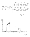
- FIG. 2 shows the associated in the video frequency position Spectrum (amount curve
- f1 is less than f2.
- FIG. 1 now becomes such an analog (Video) overall signal of an analog pulse low-pass filter 2 fed. Suppression takes place in this of disturbing image frequency parts that through the mixing process (in the video area) have arisen.
- the filtered and therefore band-limited total analog signal is one Analog / digital converter 3 supplied, at its output a digitized overall signal is created.
- the multiplier which is preferred trained as a complex multiplier is a frequency shift of the digitized overall signals such that the the spectrum belonging to the single channel in the video position lies.
- the digital low pass filter is done suppression of interfering signal components optimal frequency-side separation of the partial signals (long pulse, short pulse).
- the digital Low-pass filters are therefore preferably so-called Single pulse matched filter (on single pulses adapted filters to optimize the signal-to-noise ratio) educated. Since that (digital) Output signal of the digital low pass TP1 or TP2 significantly lower frequency components owns the corresponding digital overall signal, it is advantageous for further digital signal processing, already with this (digital) output signal the sampling frequency to a at this output signal to lower the adjusted value.
- the invention is not based on the described Embodiment limited, but analogously applicable to others, for example a pulse radar system, in addition to the described intrapulse-modulated transmission pulses still very short (unmodulated) single pulses be sent out. In such a case only one additional single channel is required. This corresponds essentially to that described but with the difference that only the digital Filters TP, P to the shape of the individual pulses have to be adjusted.
Landscapes
- Engineering & Computer Science (AREA)
- Radar, Positioning & Navigation (AREA)
- Remote Sensing (AREA)
- Computer Networks & Wireless Communication (AREA)
- Physics & Mathematics (AREA)
- General Physics & Mathematics (AREA)
- Radar Systems Or Details Thereof (AREA)
Description
Die Erfindung betrifft ein Signalverarbeitungsverfahren
für eine Pulsradaranlage nach dem Oberbegriff
des Anspruches 1 und eine Signalverarbeitungsanordnung
zur Durchführung des Verfahrens
nach dem Oberbegriff des Anspruches 5.The invention relates to a signal processing method
for a pulse radar system according to the generic term
of
Die Anwendung der Halbleitertechnik in Sendern und aktiven Array-Antennen von Pulsradaranlagen führt zur Reduktion der Sende-Spitzenleistung im Vergleich zu Röhrengeräten Zur Abdekkung der Reichweitenforderungen werden deshalb zeitlich längere Sendeimpulse benötigt, die zur Gewährleistung guter Entfernungsauflösung intrapulsmoduliert sind und empfangsseitig mit entsprechender Filtertechnik zu kurzen Signalen komprimiert werden.The application of semiconductor technology in transmitters and active array antennas of pulse radar systems leads to a reduction in the peak transmission power Compared to tube devices for covering the range requirements are therefore longer transmission pulses needed to ensure good distance resolution intrapuls modulated and on the receiving side with the corresponding Filter technology compressed into short signals will.
Das Pulsradar verwendet in der Regel die gleiche Antenne für Senden und Empfangen. Dabei kann bei kurzer Sendesignaldauer die geringfügige Totzone des Echoempfangs in Kauf genommen werden, die dadurch entsteht, daß für die Dauer des Sendesignals der Empfänger blockiert ist.The pulse radar usually uses the same one Antenna for sending and receiving. Here with a short transmission signal duration, the minor Accepted dead zone of the echo reception be created by the fact that for the duration of the transmission signal of the receiver is blocked.
Mit größerer Sendeimpulsdauer wird dieser Totbereich im Nahechoempfang unzulässig groß.With a longer transmission pulse duration, this becomes Dead area in near echo reception too large.
Aus der EP-A-0 184 424 ist eine Pulsradaranlage bekannt, die eine Sendeimpulsfolge mit zeitlich unterschiedlich langen Sendeimpulsen benutzt. Bei dieser Sendeimpulsfolge wird zunächst ein kurzer Sendeimpuls (für den Nahbereich) und nach einer kurzen Pulspause (zum Empfang der Echosignale aus dem Nahbereich) ein langer Sendeimpuls (für den Fernbereich) ausgesandt. An diesen schließt sich eine lange Pulspause an, in der Echosignale aus dem Fernbereich empfangen werden können. Der Nahbereich wird dadurch erweitert, daß die den kurzen Sendeimpulsen entsprechenden empfangenen Echosignale so verzögert werden, daß sie in das Zeitintervall fallen, in welchem der lange Sendeimpuls ausgesandt wird und in dem ansonsten der Empfänger gesperrt wird. Außerdem wird die Dauer der kurzen Pulspause fortlaufend geändert, wodurch eine ansonsten mögliche Mehrdeutigkeit der empfangenen Echosignale vermieden wird.A pulse radar system is known from EP-A-0 184 424 known that a transmission pulse sequence with time transmission pulses of different lengths are used. At this transmission pulse sequence is first a short one Send impulse (for the close range) and after one short pulse pause (for receiving the echo signals from the close range) a long transmission pulse (for the long-range area). Connects to this there is a long pause in the echo signals can be received from the far range. The close range is expanded by the fact that received according to the short transmission pulses Echo signals are delayed so that they fall in the time interval in which the long Send impulse is sent and in the otherwise the recipient is blocked. Besides, will the duration of the short pulse pause is continuously changed, which creates an otherwise possible ambiguity of the received echo signals avoided becomes.
Aus der EP-A-0 049 087 ist ein Pulserzeugungs- und Pulsauswerteverfahren, insbesondere für den Radarbereich, bekannt, bei welchem intrapulsmodulierte Pulse, die zu (Puls-)Gruppen zusammengefaßt sind, ausgesandt werden. Jede (Puls-)Gruppe enthält einen zeitlich kurzen Puls und einen zeitlich langen Puls, die unmittelbar aufeinanderfolgend (ohne Pulspause) ausgesandt werden und die unterschiedliche Frequenzanteile enthalten. Die in jeder (Puls-)Gruppe vorhandenen unterschiedlichen Pulse werden zur Erkennung von Zielen in unterschiedlichen Entfernungsbereichen verwendet. Die (Puls-)Gruppen werden an Zielen reflektiert. Die empfangenen Echosignale werden einem Empfänger zugeleitet, der einen zeitabhängig schaltbaren Entfernungstor-Schalter ("range-gate") besitzt. Dieser wählt für die Signalverarbeitung alternativ einen der nachgeschalteten, parallel liegenden Auswertezweige. In jedem Auswerte-zweig erfolgt eine selektive Detektion einer Art (kurz oder lang) der Pulse.From EP-A-0 049 087 a pulse generation and pulse evaluation methods, in particular known for the radar range, in which intrapulse modulated Pulse, which are combined into (pulse) groups are sent out. Each (Pulse) group contains a short pulse and a long pulse that is immediately consecutive (without a pulse pause) and which contain different frequency components. The different ones in each (pulse) group Pulse are used to detect Aim at different distances used. The (pulse) groups are at targets reflected. The received echo signals are forwarded to a recipient who is a time-dependent switchable range gate switch owns. This selects for the signal processing alternatively one of the downstream, parallel lying evaluation branches. In each evaluation branch there is a selective detection of a species (short or long) of the pulses.
Aus der US-A-3 945 011 ist ein Radarsystem bekannt, bei dem jeweils ein zeitlich kurzer, unmodulierter Puls (für den Nahbereich) und ein dagegen langer frequenzmodulierter Puls (für den Fernbereich) ausgesandt werden. Beide Pulse sind durch ein Zeitintervall getrennt. In diesem erfolgt eine Auswertung der aus dem Nahbereich herrührenden Echosignale. Die Auswertung erfolgt selektiv mit Hilfe eines an den kurzen Puls (Nahbereich) sowie eine an den langen Puls (Fernbereich) angepaßten Auswertekanal.US-A-3 945 011 is a radar system known, each with a short, unmodulated Pulse (for the close range) and one against long frequency modulated pulse (for the long range) be sent out. Both pulses are separated by a time interval. This is done an evaluation of those coming from the close range Echo signals. The evaluation is selective with the help of a short pulse (close range) as well as one adapted to the long pulse (far range) Evaluation channel.
Der Erfindung liegt die Aufgabe zugrunde, ein gattungsgemäßes Signalverarbeitungsverfahren anzugeben, mit dem es möglich ist, bei vorgegebener Spitzen-Sendeleistung den Erfassungsbereich einer Pulsradaranlage durch Verkleinerung der Totzone in Richtung zur Pulsradaranlage zu vergrößern.The invention is based on the object to specify the generic signal processing method, with which it is possible, given a Peak transmission power the detection area a pulse radar system by reducing the dead zone towards the pulse radar system.
Der Erfindung liegt weiterhin die Aufgabe zugrunde, eine Signalverarbeitungsanordnungzur Durchführung des Verfahrens anzugeben.The invention is further based on the object a signal processing arrangement To indicate implementation of the procedure.
Diese Aufgabe wird gelöst durch die in den
kennzeichnenden Teilen der Patentansprüche 1
und 5 angegebenen Merkmale. Vorteilhafte Ausgestaltungen
und/oder Weiterbildungen sind den weiteren
Ansprüchen entnehmbar.This task is solved by the in the
characterizing parts of
Ein erster Vorteil der Erfindung besteht darin, daß die Signalauswertung weitgehend in paralleler Weise in getrennten Signalwegen erfolgt. Dadurch können die Totzeiten, d.h. die Zeiten, in denen keine Sendesignale ausgesandt werden, erheblich verringert werden.A first advantage of the invention is that the signal evaluation largely in parallel Done in separate signal paths. Thereby the dead times, i.e. the times when no broadcast signals are sent out, significantly be reduced.
Ein zweiter Vorteil besteht darin, daß die empfangenen Echosignale nach einem Abmischvorgang in den Videobereich (0Hz bis ungefähr 10 MHz) als ein einziges analoges Gesamtsignal vorliegen. Dieses kann mit einem einzigen analogen Filter bearbeitet werden.A second advantage is that the received Echo signals after a mixing process in the video area (0Hz to about 10 MHz) are present as a single overall analog signal. This can be done with a single analog Filters can be edited.
Ein dritter Vorteil besteht darin, daß die Trennung des Gesamtsignales in die benötigten Einzelsignale und deren Weiterverarbeitung in digitaler Weise erfolgt. Dadurch ist eine sehr zuverlässige Signalverarbeitung möglich. Es wird z.B. ein Driften der Signale vermieden.A third advantage is that the separation of the overall signal into the required individual signals and their further processing in digital Way is done. This makes it a very reliable Signal processing possible. For example a drifting of signals avoided.
Ein vierter Vorteil besteht darin, daß für die Sendeimpulse für den Fern- und den Nahbereich sehr unterschiedliche Frequenzlagen und/oder Modulationsarten gewählt werden können, so daß empfangsseitig eine sehr gute Trennung der Signale möglich ist. A fourth advantage is that for the Transmission impulses for long-range and short-range very different frequency positions and / or types of modulation can be chosen so that very good separation of the signals at the receiving end is possible.
Bei der Erfindung wird unmittelbar nach dem langen, modulierten Sendeimpuls ein kurzer Sendeimpuls mit anderer Modulation und/oder Frequenzlage ausgesandt. Durch empfangsseitige Trennung der Echosignale nach Signalform und Frequenzlage kann durch die Öffnung des Empfängers unmittelbar nach Abstrahlung des kurzen Sendeimpulses der Nahbereich durch die Echoauswertung dieses Signaltyps abgedeckt werden, während für den übrigen Entfernungsbereich der Empfangskanal für das energiereichere lange Signal ausgewertet wird.In the invention is immediately after long, modulated transmit pulse a short transmit pulse with different modulation and / or frequency position sent out. By receiving Separation of the echo signals according to signal form and Frequency position can be through the opening of the receiver immediately after the short transmission pulse is emitted the close range through the echo evaluation of this type of signal are covered while the reception channel for the remaining distance range evaluated for the high-energy long signal becomes.
Es ist wichtig, daß zur Vermeidung von Übersprechen und dadurch bedingten Falschanzeigen die beiden Empfangswege eine gute Signaltrennung bezüglich der jeweils anderen Signalform bewirken und daß die Signale sendeseitig bereits durch die unterschiedliche spektrale Lage und/oder die Art ihrer Modulation oder Codierung Eigenschaften zur Selektion aufweisen.It is important to avoid crosstalk and therefore false displays the two reception paths provide good signal separation with respect to the other signal form and that the signals are already on the transmission side due to the different spectral position and / or the nature of their modulation or coding properties have for selection.
An bei der Erfindung vorteilhaften Signalmodulationsarten für die Pulsradaranwendung sind der einfache Rechteckimpuls, die Phasencodierung einer Pulsreihe (Biphasencodierung, Polyphasencodierung) und die Frequenzmodulation (linear oder nichtlinear) zu nennen. Die Signale werden in angepaßten (Matched) Filtern erkannt und zu einem kurzen Impuls entsprechend dem Kehrwert der Bandbreite komprimiert. Bei diesem Korrelationsprozeß findet gleichzeitig auch eine Dekorrelation (Dämpfung) modulationsfremder Signale im Zeitbereich statt, die aber nicht ausreicht, um z.B. die Beeinflussung eines 13 Bit Barkercode-Kanals durch ein nichtlinear-frequenzmoduliertes Signal gleicher Frequenzlage zu vermeiden.At types of signal modulation advantageous in the invention for the pulse radar application simple rectangular pulse, the phase coding of a Pulse series (biphase coding, polyphase coding) and frequency modulation (linear or non-linear). The signals are adjusted in (Matched) filters recognized and one short pulse corresponding to the reciprocal of the Bandwidth compressed. In this correlation process finds a decorrelation at the same time (Attenuation) non-modulation signals in the time domain instead, which is not sufficient to e.g. the Influencing a 13 bit bark code channel by a nonlinear frequency modulated signal to avoid the same frequency position.
Es ist deshalb zweckmäßig, daß zur unterschiedlichen Modulationsart und dadurch grundsätzlich möglichen Signaltrennung durch zeitliche Korrelation bzw. Dekorrelation die oben bereits erwähnte sendeseitige Verschiebung der Frequenzlage der Signale hinzukommt, damit eine weitere Selektion über Bandfilter erfolgen kann.It is therefore appropriate that different Modulation type and therefore fundamentally possible signal separation through temporal Correlation or decorrelation the one already mentioned above shift of the frequency position on the transmission side the signals are added, so that another Selection can be made using a band filter.
Nun hat eine solche Frequenzlagenverschiebung zur Folge, daß nach eingangsseitigen Bandfiltern für die einzelnen Signale aufwendige Empfangszüge bis zur Signalauswertung vorzusehen sind. Da der Trend aus berechtigten Gründen in Richtung einer allumfassenden digitalen Verarbeitung geht, ist es sinnvoll, eine Frequenzlagenanordnung der Signale so zu wählen, daß sie bis einschließlich einer A/D-Wandlung in einem einzigen analogen Empfangszug verarbeitet werden und erst dann mit geschickten digitalen Filtertechniken spektral getrennt und anschließend digital pulskomprimiert werden.Now has such a frequency shift with the result that after input band filters elaborate receive trains for the individual signals to be provided until signal evaluation are. As the trend in Towards all-encompassing digital processing it makes sense to use a frequency layer arrangement of the signals so that they are up to and including an A / D conversion in one analog reception train are processed and only then with clever digital filtering techniques spectrally separated and then digitally pulse compressed become.
Bei der Weiterbildung der Erfindung wurde eine Zweier- und Dreier-Kombination von Teilsignalen in verschiedener Art ihrer Frequenzlagenanordnung mit Hilfe einer Rechnersimulation untersucht, es wurden die notwendigen Filterprozesse definiert und berechnet sowie das Übersprechen des jeweils kanalfremden Signalanteils gemessen. Im Ergebnis hat sich herausgestellt, daß die Kombination eines kurzen, biphasencodierten Signals mit einem langen, linear-frequenzmodulierten Signal nach digitaler Bandfilterung und Pulskompression mit relativ geringem Aufwand zu Übersprechdämpfungen von -80 dB führt, die für den vorgesehenen Radarbetrieb sehr zufriedenstellend sind.In the development of the invention a two and three combination of partial signals in different types of their frequency layer arrangement examined with the help of a computer simulation, the necessary filter processes were defined and calculated and the crosstalk of each non-channel signal component measured. As a result it has been found that the combination of a short, biphase-coded signal with a long, linear frequency modulated signal according to digital Band filtering and pulse compression with relative low effort for crosstalk attenuation -80 dB leads for the intended radar operation are very satisfactory.
Die Erfindung wird im folgenden anhand eines Ausführungsbeispiels unter Bezugnahme auf schematische Zeichnungen näher erläutert. Es zeigen:
- FIG. 1
- ein Blockschaltbild zur Erläuterung der Erfindung
- FIG. 2
- ein beispielhaftes (Video-)Eingangssignal für eine Anordnung entpsrechend FIG. 1
- FIG. 1
- a block diagram for explaining the invention
- FIG. 2nd
- an exemplary (video) input signal for an arrangement corresponding FIG. 1
FIG. 2 zeigt in der Videofrequenzlage das zugehörige Spektrum (Betragsverlauf |X(f)|) für die Kombination aus Chirp-lmpulsen mit einer ersten Mittenfrequenz f1 und Barker-Code-lmpulsen mit einer zweiten Mittenfrequenz f2. In diesem Beispiel ist f1 kleiner als f2.FIG. 2 shows the associated in the video frequency position Spectrum (amount curve | X (f) |) for the Combination of chirp pulses with a first one Center frequency f1 and Barker code pulses with a second center frequency f2. In this example f1 is less than f2.
Gemäß FIG. 1 wird nun ein solches analoges
(Video-) Gesamtsignal einem analogen Impuls-Tiefpaßfilter
2 zugeführt. In diesem erfolgt eine Unterdrückung
von störenden Spiegelfrequenzteilen, die
durch den Abmischvorgang (in den Videobereich)
entstanden sind. Das derart gefilterte und daher
bandbegrenzte analoge Gesamtsignal wird einem
Analog/Digital-Wandler 3 zugeführt, an dessen Ausgang
ein digitalisiertes Gesamtsignal entsteht. Dieses
wird jedem der erwähnten Einzelkanäle (Signalwege),
hier beispielsweise zwei, zugeführt. In
jedem Einzelkanal muß nun zunächst das zu diesem
Kanal gehörende Frequenzband aus dem digitalisierten
Gesamtsignal herausgefiltert werden.
Dieses erfolgt in jedem Kanal vorteilhafterweise mit
Hilfe eines digitalen Multiplikators M1, M2 und eines
diesem nachgeschalteten digitalen Tiefpaßfilters
TP1, TP2. Durch den Multiplikator, der vorzugsweise
als komplexer Multiplikator ausgebildet
ist, erfolgt eine frequenzmäßige Verschiebung des
digitalisierten Gesamtsignales derart, daß das zu
dem Einzelkanal gehörende Spektrum in Videolage
liegt. Mit dem digitalen Tiefpaßfilter erfolgt außer
einer Unterdrückung störender Signalanteile auch
eine optimale frequenzseitige Trennung der Teilsignale
(langer Impuls, kurzer Impuls). Die digitalen
Tiefpaßfilter sind daher vorzugsweise als sogenannte
Single-Puls-Matched-Filter (an Einzelpulse
angepaßte Filter zur Optimierung des Signal-Rausch-Verhältnisses)
ausgebildet. Da das (digitale)
Ausgangssignal des digitalen Tiefpasses TP1
bzw. TP2 wesentlich niedrigere Frequenzanteile
besitzt als das zugehörige digitale Gesamtsignal,
ist es vorteilhaft für die weitere digitale Signalverarbeitung,
bereits bei diesem (digitalen) Ausgangssignal
die Abtastfrequenz auf einen an dieses Ausgangssignal
angepaßten Wert zu erniedrigen. Diese
Erniedrigung der Abtastfrequenz wird auch Decimation
genannt. Es ist wichtig, daß dabei keine
Information verloren geht. Diese Decimation erfolgt
daher mit Hilfe an die digitalen Tiefpaßsignale angepaßten
Interpolationen. Diese werden in Decimationsschaltungen
D1, D2 durchgeführt. Die hier entstehenden
digitalen Signale werden Pulskompressionsfiltern
P1, P2 zugeführt, in denen vorteilhafterweise
auch eine Nebenzipfelwichtung erfolgt. An
den Ausgängen A1, A2 der Pulskompressionsfilter
P1 bzw. P2 entstehen dann in digitaler Form pulsförmige
Ausgangssignale, deren Intensität proportional
zur Länge der unkomprimierten Signale ist.
Diese Ausgangssignale besitzen vorteilhafterweise
einen sehr hohen Störspannungsabstand bezüglich
den Signalen des Nachbarkanales, z.B. mindestens
80 dB, und können in nicht dargestellten Anordnungen
weiterverarbeitet werden, z.B. für eine Auswertung
auf einem (Radar-) Bildschirm.According to FIG. 1 now becomes such an analog
(Video) overall signal of an analog pulse low-
Die Erfindung ist nicht auf das beschriebene Ausführungsbeispiel beschränkt, sondern sinngemäß auf weitere anwendbar, beispielsweise auf eine Pulsradaranlage, bei der zusätzlich zu den beschriebenen intrapulsmodulierten Sendeimpulsen noch dagegen sehr kurze (unmodulierte) Einzelimpulse ausgesandt werden. In einem solchen Fall ist lediglich ein weiterer Einzelkanal erforderlich. Dieser entspricht im wesentlichen den beschriebenen jedoch mit dem Unterschied, daß lediglich die digitalen Filter TP, P an die Form der Einzelimpulse angepaßt werden müssen.The invention is not based on the described Embodiment limited, but analogously applicable to others, for example a pulse radar system, in addition to the described intrapulse-modulated transmission pulses still very short (unmodulated) single pulses be sent out. In such a case only one additional single channel is required. This corresponds essentially to that described but with the difference that only the digital Filters TP, P to the shape of the individual pulses have to be adjusted.
Es ist vorteilhaft, die Sendersignalspektren möglichst schmal zu gestalten, um den benötigten Frequenzbereich für die Anordnung der Kanäle gering zu halten und eine Überlappung der Spektren zu vermeiden, damit eine gute Selektion möglich bleibt. So kann z. B. die Phasenänderung beim biphasencodierten Signal in linearer Weise über einen verträglichen Zeitbereich erfolgen, anstatt einer abrupten Umtastung. Dadurch entsteht eine erhebliche Reduktion der spektralen Ausdehnung.It is advantageous to use the transmitter signal spectra as narrow as possible in order to achieve the required Frequency range for the arrangement of the channels is small to keep and overlap the spectra to avoid, so that a good selection is possible remains. So z. B. the phase change at biphase-encoded signal in a linear fashion a tolerable time period instead of one abrupt shift keying. This creates one considerable reduction of the spectral expansion.
Claims (7)
- Signal-processing method for a pulse radar installation consisting of at least one ofcharacterised therebya transmitting and receiving aerial,at least one pulse generator, which is coupled to the transmitting and receiving aerial, for the production of an intrapulse-modulated transmitted pulse, which is long in time, for the distant range and an intrapulse-modulated transmitted pulse, which is short in time and follows the long transmitted pulse directly in time, for the close range, wherein the long and short transmitted pulse differ by a different frequency position,a receiving equipment, which is coupled to the transmitting and receiving aerial, for the evaluation of the echo pulses corresponding to the transmitted pulses,wherein the received echo pulses are initially translated into a lower frequency range andthe echo signals are then separated for the close and the distant range and subsequently evaluated separately in different signal paths,that the received echo signals are mixed down into a video-frequency position, so that a single analog total signal (X(f)) arises in a single channel,that the analog total signal (X(f)) is fed to an anlog filtering (2) at which mirror frequency components are suppressed, so that a band-limited analog total signal arises after the filtering (2),that the analog total signal is converted in an analog-to-digital converter (3) into a digital total signal,that the digital total signal is applied to at least two parallel individual channels which are associated with the long as well as the short transmitted pulse, andthat the digital total signal is shifted in each of the individual channels by a complex multiplication (M1, M2) into a low pass position, in which a digital filtering (TP1, TP2), which is adapted to the kind of transmitted pulse to be detected, as well as a pulse compression are undertaken.
- Signal-processing method according to claim 1, characterised thereby, that the long transmitted pulse contains a frequency-modulated signal with a monotically changing frequency and that a pulse-coded signal is used for the short transmitted pulse.
- Signal-processing method according to claim 1 or 2, characterised thereby, that the long transmitted pulse contains a frequency-modulated signal with a linearly rising frequency and that a signal, which is phase-coded according to the Barker code, is used for the short transmitted pulse.
- Signal-processing method according to one of the preceding claims, characterised thereby, that an amplitude modulation is carried out in addition for the long frequency-modulated transmitted pulse in such a manner that the amplitude has a maximum value in the temporal centre of the long transmitted pulse.
- Signal-processing arrangement for the performance of the method according to claim 1 and consisting of at least one ofcharacterised thereby,a transmitting and receiving aerial,at least one pulse generator, which is coupled to the transmitting and receiving aerial, for the production of an intrapulse-modulated transmitted pulse, which is long in time, for the distant range and an intrapulse-modulated transmitted pulse, which is short in time and follows the long transmitted pulse directly in time, for the close range, wherein the long and short transmitted pulse differ by a different frequency position,a receiving equipment, which is coupled to the transmitting and receiving aerial, for the evaluation of the echo pulses corresponding to the transmitted pulses,wherein the received echo pulses are initially translated into a lower frequency range,that the arrangement comprises means for mixing the received echo signals down into a video-frequency position,that an analog low-pass filter (2) is present, in which a suppression of interfering image-frequency components of the echo pulses (X(f)) mixed down into the video range is undertaken,that an analog-to-digital converter (3), at the output of which a digital total signal arises, is connected behind the low-pass pulse filter (2),that the parallelly connected inputs of at least two individual channels are connected to the analog-to-digital converter (3),that a digital filtering of the frequency band belonging to an individual channel out of the digital total signal takes place in each individual channel thereby,that a multiplier (M1, M2), in which the digital total signal is shifted into a low-pass position, is present in each individual channel,that a digital low-pass filter (TP1, TP2), in which a matched filtering is performed in addition, is connected to the output of the multiplier (M1, M2) andthat a pulse compression filter (P1, P2) is connected behind each digital low-pass filter digital low-pass filter (TP1, TP2).
- Signal-processing arrangement according to claim 5, characterised thereby, that at least one multiplier (Ml, M2) is constructed for a complex multiplication of the digital total signal.
- Signal-processing arrangement according to claim 5 or 6, characterised thereby, a decimation circuit (D1, D2), which enables a lowering of the scanning frequency of the digital output signal of the digital low-pass filter (TP1, TP2), is present in at least one individual channel.
Applications Claiming Priority (4)
| Application Number | Priority Date | Filing Date | Title |
|---|---|---|---|
| DE4006981 | 1990-03-07 | ||
| DE4006981 | 1990-03-07 | ||
| DE4105977A DE4105977A1 (en) | 1990-03-07 | 1991-02-26 | SIGNAL PROCESSING METHOD AND SIGNAL PROCESSING ARRANGEMENT FOR A PULSE RADAR SYSTEM |
| DE4105977 | 1991-02-26 |
Publications (3)
| Publication Number | Publication Date |
|---|---|
| EP0447874A1 EP0447874A1 (en) | 1991-09-25 |
| EP0447874B1 EP0447874B1 (en) | 1995-10-04 |
| EP0447874B2 true EP0447874B2 (en) | 1999-06-23 |
Family
ID=25890822
Family Applications (1)
| Application Number | Title | Priority Date | Filing Date |
|---|---|---|---|
| EP91103343A Expired - Lifetime EP0447874B2 (en) | 1990-03-07 | 1991-03-06 | Method and device for signal processing in a pulsed radar system |
Country Status (2)
| Country | Link |
|---|---|
| EP (1) | EP0447874B2 (en) |
| DE (2) | DE4105977A1 (en) |
Families Citing this family (5)
| Publication number | Priority date | Publication date | Assignee | Title |
|---|---|---|---|---|
| DE4433775A1 (en) * | 1994-09-22 | 1996-03-28 | Daimler Benz Ag | Pulse radar method |
| DE102007029959A1 (en) * | 2007-06-28 | 2009-01-02 | Robert Bosch Gmbh | Method and device for detecting an environment |
| JP2012103196A (en) * | 2010-11-12 | 2012-05-31 | Japan Radio Co Ltd | Radar device |
| DE102013022273A1 (en) | 2013-05-08 | 2014-11-13 | Elmos Semiconductor Ag | Method for measuring a distance by means of ultrasound |
| DE102013008235A1 (en) * | 2013-05-08 | 2014-11-13 | Elmos Semiconductor Ag | Method for measuring a distance by means of ultrasound |
Family Cites Families (3)
| Publication number | Priority date | Publication date | Assignee | Title |
|---|---|---|---|---|
| GB1424026A (en) * | 1973-11-13 | 1976-02-04 | Marconi Co Ltd | Radar systems |
| DE3175682D1 (en) * | 1980-09-27 | 1987-01-15 | Marconi Co Ltd | Radar, sonar and similar systems |
| JPS61133885A (en) * | 1984-12-04 | 1986-06-21 | Nec Corp | Inter-pulse interference removing system for composite pulse radar |
-
1991
- 1991-02-26 DE DE4105977A patent/DE4105977A1/en not_active Ceased
- 1991-03-06 EP EP91103343A patent/EP0447874B2/en not_active Expired - Lifetime
- 1991-03-06 DE DE59106606T patent/DE59106606D1/en not_active Expired - Fee Related
Also Published As
| Publication number | Publication date |
|---|---|
| EP0447874A1 (en) | 1991-09-25 |
| DE4105977A1 (en) | 1991-09-12 |
| EP0447874B1 (en) | 1995-10-04 |
| DE59106606D1 (en) | 1995-11-09 |
Similar Documents
| Publication | Publication Date | Title |
|---|---|---|
| DE2749497C2 (en) | ||
| DE3787015T2 (en) | IMPULSE RADIATION RADAR DEVICE IN THE FREQUENCY RANGE FOR ELIMINATION OF INTERFERENCE. | |
| DE69212079T2 (en) | Radar | |
| WO2002014902A1 (en) | Method for pulse width modulation of a radar system | |
| DE3887745T2 (en) | Radar using different types of pulses. | |
| EP0355336B1 (en) | Radar system for position determination of two or more objects | |
| DE69922428T2 (en) | Continuous wave radar receiver with frequency hopping | |
| DE2936168C2 (en) | ||
| DE102013216461A1 (en) | Synthetic aperture radar method for remote sensing of surface of earth through radar system, involves generating sub-pulses in respective pulse repetition interval such that sub-pulses have different, non-overlapping frequency ranges | |
| DE69827057T2 (en) | Noise reduction device for radar receiver | |
| EP0447874B2 (en) | Method and device for signal processing in a pulsed radar system | |
| DE3041459C2 (en) | ||
| DE3132268C1 (en) | Pulse Doppler radar device | |
| DE3347455C2 (en) | ||
| DE69734345T2 (en) | Method for transmitting radar transmission pulses | |
| DE2433203C3 (en) | Frequency-shifting Doppler radar system for measuring distance and speed | |
| DE10142171A1 (en) | Vehicle radar set includes local oscillator with signal splitter feeding phase shift transmitter unit and mixers in reception train registering phase-shifted returns | |
| EP0789252B1 (en) | Method of suppression of inteference signals in a puls doppler radar | |
| DE2204096C3 (en) | ||
| EP0703465B1 (en) | Pulse radar method | |
| DE977595C (en) | Method for the temporal compression of the echo pulses of a radar device as well as radar device for the application of the method | |
| DE69314535T2 (en) | Radar | |
| DE3240904C1 (en) | Message receiver has convolution unit that outputs fully correlated intermediate frequency signal of bit amplitude IF reference signal, message information bit exactly correlate and overlap | |
| DE977829C (en) | Radar device to eliminate the echoes that are thrown back from fixed or slowly moving targets, for example metallic collision reflectors | |
| DE3520310C2 (en) | Procedure for eliminating the ambiguity of distance as well as transmitter in a pulse Doppler radar device and receiver for performing this procedure |
Legal Events
| Date | Code | Title | Description |
|---|---|---|---|
| PUAI | Public reference made under article 153(3) epc to a published international application that has entered the european phase |
Free format text: ORIGINAL CODE: 0009012 |
|
| AK | Designated contracting states |
Kind code of ref document: A1 Designated state(s): DE FR GB |
|
| 17P | Request for examination filed |
Effective date: 19920312 |
|
| RAP1 | Party data changed (applicant data changed or rights of an application transferred) |
Owner name: TELEFUNKEN SYSTEMTECHNIK AG |
|
| RAP1 | Party data changed (applicant data changed or rights of an application transferred) |
Owner name: DEUTSCHE AEROSPACE AKTIENGESELLSCHAFT |
|
| 17Q | First examination report despatched |
Effective date: 19940121 |
|
| RAP1 | Party data changed (applicant data changed or rights of an application transferred) |
Owner name: DAIMLER-BENZ AEROSPACE AKTIENGESELLSCHAFT |
|
| GRAA | (expected) grant |
Free format text: ORIGINAL CODE: 0009210 |
|
| AK | Designated contracting states |
Kind code of ref document: B1 Designated state(s): DE FR GB |
|
| REF | Corresponds to: |
Ref document number: 59106606 Country of ref document: DE Date of ref document: 19951109 |
|
| GBT | Gb: translation of ep patent filed (gb section 77(6)(a)/1977) |
Effective date: 19951026 |
|
| ET | Fr: translation filed | ||
| PLBI | Opposition filed |
Free format text: ORIGINAL CODE: 0009260 |
|
| PLBF | Reply of patent proprietor to notice(s) of opposition |
Free format text: ORIGINAL CODE: EPIDOS OBSO |
|
| 26 | Opposition filed |
Opponent name: SIEMENS AG Effective date: 19960701 |
|
| PLBF | Reply of patent proprietor to notice(s) of opposition |
Free format text: ORIGINAL CODE: EPIDOS OBSO |
|
| PLAW | Interlocutory decision in opposition |
Free format text: ORIGINAL CODE: EPIDOS IDOP |
|
| PLAW | Interlocutory decision in opposition |
Free format text: ORIGINAL CODE: EPIDOS IDOP |
|
| PUAH | Patent maintained in amended form |
Free format text: ORIGINAL CODE: 0009272 |
|
| STAA | Information on the status of an ep patent application or granted ep patent |
Free format text: STATUS: PATENT MAINTAINED AS AMENDED |
|
| 27A | Patent maintained in amended form |
Effective date: 19990623 |
|
| AK | Designated contracting states |
Kind code of ref document: B2 Designated state(s): DE FR GB |
|
| GBTA | Gb: translation of amended ep patent filed (gb section 77(6)(b)/1977) | ||
| ET3 | Fr: translation filed ** decision concerning opposition | ||
| REG | Reference to a national code |
Ref country code: GB Ref legal event code: IF02 |
|
| PGFP | Annual fee paid to national office [announced via postgrant information from national office to epo] |
Ref country code: DE Payment date: 20030311 Year of fee payment: 13 |
|
| PG25 | Lapsed in a contracting state [announced via postgrant information from national office to epo] |
Ref country code: DE Free format text: LAPSE BECAUSE OF NON-PAYMENT OF DUE FEES Effective date: 20041001 |
|
| PGFP | Annual fee paid to national office [announced via postgrant information from national office to epo] |
Ref country code: GB Payment date: 20090325 Year of fee payment: 19 |
|
| PGFP | Annual fee paid to national office [announced via postgrant information from national office to epo] |
Ref country code: FR Payment date: 20090312 Year of fee payment: 19 |
|
| GBPC | Gb: european patent ceased through non-payment of renewal fee |
Effective date: 20100306 |
|
| REG | Reference to a national code |
Ref country code: FR Ref legal event code: ST Effective date: 20101130 |
|
| PG25 | Lapsed in a contracting state [announced via postgrant information from national office to epo] |
Ref country code: FR Free format text: LAPSE BECAUSE OF NON-PAYMENT OF DUE FEES Effective date: 20100331 |
|
| PG25 | Lapsed in a contracting state [announced via postgrant information from national office to epo] |
Ref country code: GB Free format text: LAPSE BECAUSE OF NON-PAYMENT OF DUE FEES Effective date: 20100306 |