EP0447874B2 - Méthode et appareil pour le traitement de signaux dans un système radar à impulsions - Google Patents
Méthode et appareil pour le traitement de signaux dans un système radar à impulsions Download PDFInfo
- Publication number
- EP0447874B2 EP0447874B2 EP91103343A EP91103343A EP0447874B2 EP 0447874 B2 EP0447874 B2 EP 0447874B2 EP 91103343 A EP91103343 A EP 91103343A EP 91103343 A EP91103343 A EP 91103343A EP 0447874 B2 EP0447874 B2 EP 0447874B2
- Authority
- EP
- European Patent Office
- Prior art keywords
- signal
- pulse
- digital
- frequency
- long
- Prior art date
- Legal status (The legal status is an assumption and is not a legal conclusion. Google has not performed a legal analysis and makes no representation as to the accuracy of the status listed.)
- Expired - Lifetime
Links
- 238000012545 processing Methods 0.000 title claims description 14
- 238000000034 method Methods 0.000 title claims description 9
- 238000011156 evaluation Methods 0.000 claims description 12
- 238000001914 filtration Methods 0.000 claims description 7
- 238000003672 processing method Methods 0.000 claims description 6
- 230000006835 compression Effects 0.000 claims description 5
- 238000007906 compression Methods 0.000 claims description 5
- 230000001629 suppression Effects 0.000 claims description 3
- 230000002452 interceptive effect Effects 0.000 claims description 2
- 230000002123 temporal effect Effects 0.000 claims description 2
- 238000004519 manufacturing process Methods 0.000 claims 2
- 238000009434 installation Methods 0.000 claims 1
- 230000000630 rising effect Effects 0.000 claims 1
- 230000005540 biological transmission Effects 0.000 description 23
- 238000000926 separation method Methods 0.000 description 6
- 238000001228 spectrum Methods 0.000 description 4
- 238000001208 nuclear magnetic resonance pulse sequence Methods 0.000 description 3
- 238000001514 detection method Methods 0.000 description 2
- 238000010586 diagram Methods 0.000 description 2
- 230000036961 partial effect Effects 0.000 description 2
- 238000005070 sampling Methods 0.000 description 2
- 230000003595 spectral effect Effects 0.000 description 2
- 238000006243 chemical reaction Methods 0.000 description 1
- 238000005094 computer simulation Methods 0.000 description 1
- 230000003247 decreasing effect Effects 0.000 description 1
- 230000003111 delayed effect Effects 0.000 description 1
- 238000011161 development Methods 0.000 description 1
- 230000002829 reductive effect Effects 0.000 description 1
- 239000004065 semiconductor Substances 0.000 description 1
- 230000036962 time dependent Effects 0.000 description 1
- 238000012549 training Methods 0.000 description 1
Images
Classifications
-
- G—PHYSICS
- G01—MEASURING; TESTING
- G01S—RADIO DIRECTION-FINDING; RADIO NAVIGATION; DETERMINING DISTANCE OR VELOCITY BY USE OF RADIO WAVES; LOCATING OR PRESENCE-DETECTING BY USE OF THE REFLECTION OR RERADIATION OF RADIO WAVES; ANALOGOUS ARRANGEMENTS USING OTHER WAVES
- G01S13/00—Systems using the reflection or reradiation of radio waves, e.g. radar systems; Analogous systems using reflection or reradiation of waves whose nature or wavelength is irrelevant or unspecified
- G01S13/02—Systems using reflection of radio waves, e.g. primary radar systems; Analogous systems
- G01S13/06—Systems determining position data of a target
- G01S13/08—Systems for measuring distance only
- G01S13/10—Systems for measuring distance only using transmission of interrupted, pulse modulated waves
- G01S13/30—Systems for measuring distance only using transmission of interrupted, pulse modulated waves using more than one pulse per radar period
-
- G—PHYSICS
- G01—MEASURING; TESTING
- G01S—RADIO DIRECTION-FINDING; RADIO NAVIGATION; DETERMINING DISTANCE OR VELOCITY BY USE OF RADIO WAVES; LOCATING OR PRESENCE-DETECTING BY USE OF THE REFLECTION OR RERADIATION OF RADIO WAVES; ANALOGOUS ARRANGEMENTS USING OTHER WAVES
- G01S13/00—Systems using the reflection or reradiation of radio waves, e.g. radar systems; Analogous systems using reflection or reradiation of waves whose nature or wavelength is irrelevant or unspecified
- G01S13/02—Systems using reflection of radio waves, e.g. primary radar systems; Analogous systems
- G01S13/06—Systems determining position data of a target
- G01S13/08—Systems for measuring distance only
- G01S13/32—Systems for measuring distance only using transmission of continuous waves, whether amplitude-, frequency-, or phase-modulated, or unmodulated
- G01S13/36—Systems for measuring distance only using transmission of continuous waves, whether amplitude-, frequency-, or phase-modulated, or unmodulated with phase comparison between the received signal and the contemporaneously transmitted signal
- G01S13/38—Systems for measuring distance only using transmission of continuous waves, whether amplitude-, frequency-, or phase-modulated, or unmodulated with phase comparison between the received signal and the contemporaneously transmitted signal wherein more than one modulation frequency is used
-
- G—PHYSICS
- G01—MEASURING; TESTING
- G01S—RADIO DIRECTION-FINDING; RADIO NAVIGATION; DETERMINING DISTANCE OR VELOCITY BY USE OF RADIO WAVES; LOCATING OR PRESENCE-DETECTING BY USE OF THE REFLECTION OR RERADIATION OF RADIO WAVES; ANALOGOUS ARRANGEMENTS USING OTHER WAVES
- G01S7/00—Details of systems according to groups G01S13/00, G01S15/00, G01S17/00
- G01S7/02—Details of systems according to groups G01S13/00, G01S15/00, G01S17/00 of systems according to group G01S13/00
- G01S7/28—Details of pulse systems
- G01S7/285—Receivers
- G01S7/292—Extracting wanted echo-signals
- G01S7/2921—Extracting wanted echo-signals based on data belonging to one radar period
Definitions
- the invention relates to a signal processing method for a pulse radar system according to the generic term of claim 1 and a signal processing arrangement to carry out the procedure according to the preamble of claim 5.
- the pulse radar usually uses the same one Antenna for sending and receiving.
- the minor Accepted dead zone of the echo reception be created by the fact that for the duration of the transmission signal of the receiver is blocked.
- a pulse radar system is known from EP-A-0 184 424 known that a transmission pulse sequence with time transmission pulses of different lengths are used. At this transmission pulse sequence is first a short one Send impulse (for the close range) and after one short pulse pause (for receiving the echo signals from the close range) a long transmission pulse (for the long-range area). Connects to this there is a long pause in the echo signals can be received from the far range.
- the close range is expanded by the fact that received according to the short transmission pulses Echo signals are delayed so that they fall in the time interval in which the long Send impulse is sent and in the otherwise the recipient is blocked. Besides, will the duration of the short pulse pause is continuously changed, which creates an otherwise possible ambiguity of the received echo signals avoided becomes.
- a pulse generation and pulse evaluation methods in particular known for the radar range, in which intrapulse modulated Pulse, which are combined into (pulse) groups are sent out.
- Each (Pulse) group contains a short pulse and a long pulse that is immediately consecutive (without a pulse pause) and which contain different frequency components.
- the different ones in each (pulse) group Pulse are used to detect Aim at different distances used.
- the (pulse) groups are at targets reflected.
- the received echo signals are forwarded to a recipient who is a time-dependent switchable range gate switch owns. This selects for the signal processing alternatively one of the downstream, parallel lying evaluation branches. In each evaluation branch there is a selective detection of a species (short or long) of the pulses.
- US-A-3 945 011 is a radar system known, each with a short, unmodulated Pulse (for the close range) and one against long frequency modulated pulse (for the long range) be sent out. Both pulses are separated by a time interval. This is done an evaluation of those coming from the close range Echo signals. The evaluation is selective with the help of a short pulse (close range) as well as one adapted to the long pulse (far range) Evaluation channel.
- the invention is based on the object to specify the generic signal processing method, with which it is possible, given a Peak transmission power the detection area a pulse radar system by reducing the dead zone towards the pulse radar system.
- the invention is further based on the object a signal processing arrangement To indicate implementation of the procedure.
- a first advantage of the invention is that the signal evaluation largely in parallel Done in separate signal paths. Thereby the dead times, i.e. the times when no broadcast signals are sent out, significantly be reduced.
- a second advantage is that the received Echo signals after a mixing process in the video area (0Hz to about 10 MHz) are present as a single overall analog signal. This can be done with a single analog Filters can be edited.
- a third advantage is that the separation of the overall signal into the required individual signals and their further processing in digital Way is done. This makes it a very reliable Signal processing possible. For example a drifting of signals avoided.
- a fourth advantage is that for the Transmission impulses for long-range and short-range very different frequency positions and / or types of modulation can be chosen so that very good separation of the signals at the receiving end is possible.
- a short transmit pulse with different modulation and / or frequency position sent out.
- the close range through the echo evaluation of this type of signal are covered while the reception channel for the remaining distance range evaluated for the high-energy long signal becomes.
- the two reception paths provide good signal separation with respect to the other signal form and that the signals are already on the transmission side due to the different spectral position and / or the nature of their modulation or coding properties have for selection.
- phase coding of a Pulse series (biphase coding, polyphase coding) and frequency modulation (linear or non-linear).
- the signals are adjusted in (Matched) filters recognized and one short pulse corresponding to the reciprocal of the Bandwidth compressed.
- This correlation process finds a decorrelation at the same time (Attenuation) non-modulation signals in the time domain instead, which is not sufficient to e.g. the Influencing a 13 bit bark code channel by a nonlinear frequency modulated signal to avoid the same frequency position.
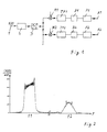
- FIG. 2 shows the associated in the video frequency position Spectrum (amount curve
- f1 is less than f2.
- FIG. 1 now becomes such an analog (Video) overall signal of an analog pulse low-pass filter 2 fed. Suppression takes place in this of disturbing image frequency parts that through the mixing process (in the video area) have arisen.
- the filtered and therefore band-limited total analog signal is one Analog / digital converter 3 supplied, at its output a digitized overall signal is created.
- the multiplier which is preferred trained as a complex multiplier is a frequency shift of the digitized overall signals such that the the spectrum belonging to the single channel in the video position lies.
- the digital low pass filter is done suppression of interfering signal components optimal frequency-side separation of the partial signals (long pulse, short pulse).
- the digital Low-pass filters are therefore preferably so-called Single pulse matched filter (on single pulses adapted filters to optimize the signal-to-noise ratio) educated. Since that (digital) Output signal of the digital low pass TP1 or TP2 significantly lower frequency components owns the corresponding digital overall signal, it is advantageous for further digital signal processing, already with this (digital) output signal the sampling frequency to a at this output signal to lower the adjusted value.
- the invention is not based on the described Embodiment limited, but analogously applicable to others, for example a pulse radar system, in addition to the described intrapulse-modulated transmission pulses still very short (unmodulated) single pulses be sent out. In such a case only one additional single channel is required. This corresponds essentially to that described but with the difference that only the digital Filters TP, P to the shape of the individual pulses have to be adjusted.
Landscapes
- Engineering & Computer Science (AREA)
- Radar, Positioning & Navigation (AREA)
- Remote Sensing (AREA)
- Computer Networks & Wireless Communication (AREA)
- Physics & Mathematics (AREA)
- General Physics & Mathematics (AREA)
- Radar Systems Or Details Thereof (AREA)
Claims (7)
- Procédé de traitement de signal pour une installation de radar pulsé constituée au moins :caractérisé en ce,d'une antenne d'émission et de réception,d'au moins un générateur d'impulsions couplé à l'antenne d'émission et de réception, pour l'engendrement d'une impulsion d'émission, longue dans le temps, modulée de façon intrapulsée, pour la région éloignée, et d'une impulsion d'émission, modulée de façon intrapulsée, courte dans le temps, se raccordant directement dans le temps à l'impulsion d'émission longue, pour la région proche, l'impulsion d'émission longue et l'impulsion d'émission courte se différenciant par une position en fréquence différente,d'un agencement de réception couplé à l'antenne d'émission et de réception, pour l'évaluation des impulsions d'écho correspondant aux impulsions d'émission,les impulsions d'écho reçues étant converties tout d'abord dans une plage de fréquences plus faible, etles signaux d'écho pour la région proche ainsi que la région éloignée étant alors séparés et, consécutivement étant évalués, séparés, dans des trajets de signal différents,que les signaux d'écho reçus sont abaissés par mélange dans une position en fréquence vidéo, de sorte qu'un signal total analogique (X(f)) unique prend naissance dans un seul canal,que le signal total analogique (X(f)) est envoyé à une filtration analogique (2) lors de laquelle des quote-parts de fréquence de miroir sont supprimées, de sorte qu'un signal total analogique limité au point de vue bande prend naissance après la filtration (2),que le signal total analogique est converti, dans un convertisseur (3) analogique/numérique, en un signal total numérique,que le signal total numérique est appliqué à au moins deux canaux individuels se trouvant parallèles, lesquels sont associés à l'impulsion d'émission longue ainsi qu'à l'impulsion d'émission courte, etque dans chacun des canaux individuels, le signal total numérique est décalé par une multiplication (M1, M2) complexe dans une position passe-bas, dans laquelle, une filtration (TP1, TP2) numérique adaptée au type d'impulsion d'émission à détecter, ainsi qu'une compression d'impulsions (P1, P2), sont effectuées.
- Procédé de traitement de signal selon la revendication 1, caractérisé en ce que l'impulsion d'émission longue contient un signal modulé en fréquence, avec une fréquence se modifiant de façon monotone, et en ce qu'un signal codé au point de vue phase est employé pour l'impulsion d'émission courte.
- Procédé de traitement de signal selon la revendication 1 ou la revendication 2, caractérisé en ce que l'impulsion d'émission longue contient un signal modulé en fréquence, avec une fréquence croissant linéairement, et en ce qu'un signal codé au point de vue phase, correspondant au code de Barker, est employé pour l'impulsion d'émission courte.
- Procédé de traitement de signal selon une des précédentes revendications, caractérisé en ce que, lors de l'impulsion d'émission modulée en fréquence longue, en supplément, une modulation d'amplitude est exécutée de telle sorte, que l'amplitude possède une valeur maximale dans le milieu dans le temps de l'impulsion d'émission longue.
- Agencement de traitement de signal pour la mise en oeuvre du procédé selon la revendication 1, consistant au moins en :une antenne d'émission et de réception,au moins un générateur d'impulsions couplé à l'antenne d'émission et de réception, pour l'engendrement d'une impulsion d'émission, modulée de façon intrapulsée, longue dans le temps, pour la région éloignée, et d'une impulsion d'émission, modulée de façon intrapulsée, courte dans le temps, se raccordant directement dans le temps à l'impulsion d'émission longue, pour la région proche, l'impulsion d'émission longue et l'impulsion d'émission courte se différenciant par une position en fréquence différente,d'un agencement de réception couplé à l'antenne d'émission et de réception, pour l'évaluation des impulsions d'écho correspondant aux impulsions d'émission,les impulsions d'écho reçues étant tout d'abord converties dans une plage de fréquences plus faibles,caractérisé en ceque l'agencement présente des moyens pour l'abaissement par mélange des signaux d'écho reçus dans une position en fréquence vidéo,qu'un filtre d'impulsion passe-bas (2) analogique, dans lequel une suppression de quote-part de fréquence de miroir, perturbatrice des impulsions d'écho (X(f)), abaissée par mélange dans la plage vidéo, est effectuée, est présent,qu'au filtre d'impulsion passe-bas (2), est mis en circuit en aval un convertisseur analogique/numérique (3), à la sortie duquel un signal total numérique prend naissance,qu'au convertisseur analogique/numérique (3), sont raccordées les entrées, mises en circuit en parallèle, d'au moins deux canaux individuels,que dans chaque canal individuel, une extraction par filtration numérique de la bande de fréquence appartenant au canal individuel, hors du signal total numérique, a lieu grâce à ce,que dans chaque canal individuel, un multiplicateur (M1, M2), dans lequel le signal total numérique est décalé dans une position passe-bas, est présent,qu'à la sortie du multiplicateur (M1, M2), est raccordé un filtre passe-bas (TP1, TP2) numérique, dans lequel, de façon supplémentaire, une filtration "matched" est exécutée, etqu'à chaque filtre passe-bas (TP1, TP2) numérique, un filtre de compression d'impulsion (P1, P2) est mis en circuit en aval.
- Agencement de traitement de signal selon la revendication 5, caractérisé en ce qu'au moins un multiplicateur (M1, M2) est constitué pour une multiplication complexe du signal total numérique.
- Agencement de traitement de signal selon la revendication 5 ou la revendication 6, caractérisé en ce que, dans au moins un canal individuel, un circuit de décimation (D1, D2) est présent, qui rend possible un abaissement de la fréquence d'exploration du signal de sortie numérique du filtre passe-bas (TP1, TP2).
Applications Claiming Priority (4)
| Application Number | Priority Date | Filing Date | Title |
|---|---|---|---|
| DE4006981 | 1990-03-07 | ||
| DE4006981 | 1990-03-07 | ||
| DE4105977A DE4105977A1 (de) | 1990-03-07 | 1991-02-26 | Signalverarbeitungsverfahren und signalverarbeitungsanordnung fuer eine pulsradaranlage |
| DE4105977 | 1991-02-26 |
Publications (3)
| Publication Number | Publication Date |
|---|---|
| EP0447874A1 EP0447874A1 (fr) | 1991-09-25 |
| EP0447874B1 EP0447874B1 (fr) | 1995-10-04 |
| EP0447874B2 true EP0447874B2 (fr) | 1999-06-23 |
Family
ID=25890822
Family Applications (1)
| Application Number | Title | Priority Date | Filing Date |
|---|---|---|---|
| EP91103343A Expired - Lifetime EP0447874B2 (fr) | 1990-03-07 | 1991-03-06 | Méthode et appareil pour le traitement de signaux dans un système radar à impulsions |
Country Status (2)
| Country | Link |
|---|---|
| EP (1) | EP0447874B2 (fr) |
| DE (2) | DE4105977A1 (fr) |
Families Citing this family (5)
| Publication number | Priority date | Publication date | Assignee | Title |
|---|---|---|---|---|
| DE4433775A1 (de) * | 1994-09-22 | 1996-03-28 | Daimler Benz Ag | Puls-Radarverfahren |
| DE102007029959A1 (de) * | 2007-06-28 | 2009-01-02 | Robert Bosch Gmbh | Verfahren und Vorrichtung zur Erfassung einer Umgebung |
| JP2012103196A (ja) * | 2010-11-12 | 2012-05-31 | Japan Radio Co Ltd | レーダ装置 |
| DE102013022273A1 (de) | 2013-05-08 | 2014-11-13 | Elmos Semiconductor Ag | Verfahren zur Messung eines Abstands mittels Ultraschall |
| DE102013008235A1 (de) * | 2013-05-08 | 2014-11-13 | Elmos Semiconductor Ag | Verfahren zur Messung eines Abstands mittels Ultraschall |
Family Cites Families (3)
| Publication number | Priority date | Publication date | Assignee | Title |
|---|---|---|---|---|
| GB1424026A (en) * | 1973-11-13 | 1976-02-04 | Marconi Co Ltd | Radar systems |
| EP0049087B2 (fr) * | 1980-09-27 | 1991-03-13 | The Marconi Company Limited | Radar, sonar et systèmes semblables |
| JPS61133885A (ja) * | 1984-12-04 | 1986-06-21 | Nec Corp | 複合パルスレ−ダのパルス間干渉除去方式 |
-
1991
- 1991-02-26 DE DE4105977A patent/DE4105977A1/de not_active Ceased
- 1991-03-06 EP EP91103343A patent/EP0447874B2/fr not_active Expired - Lifetime
- 1991-03-06 DE DE59106606T patent/DE59106606D1/de not_active Expired - Fee Related
Also Published As
| Publication number | Publication date |
|---|---|
| DE59106606D1 (de) | 1995-11-09 |
| EP0447874B1 (fr) | 1995-10-04 |
| DE4105977A1 (de) | 1991-09-12 |
| EP0447874A1 (fr) | 1991-09-25 |
Similar Documents
| Publication | Publication Date | Title |
|---|---|---|
| DE2749497C2 (fr) | ||
| DE3787015T2 (de) | Im frequenzbereich wirkendes impulsraffungsradargerät zur störechobeseitigung. | |
| DE69212079T2 (de) | Radargerät | |
| EP1309885A1 (fr) | Procede de modulation d'impulsion en largeur d'un systeme radar | |
| DE3887745T2 (de) | Radargerät unter Verwendung von verschiedener Arten von Impulsen. | |
| EP0355336B1 (fr) | Système radar pour la détermination de la position de deux ou plusieurs objets | |
| DE69922428T2 (de) | Dauerstrichradar-Empfänger mit Frequenzsprung | |
| DE2936168C2 (fr) | ||
| DE102013216461A1 (de) | Synthetik-Apertur-Radarverfahren | |
| DE69827057T2 (de) | Geräuschreduzierungsvorrichtung für Radarempfänger | |
| EP0447874B2 (fr) | Méthode et appareil pour le traitement de signaux dans un système radar à impulsions | |
| DE3041459C2 (fr) | ||
| DE3132268C1 (de) | Puls-Doppler-Radargeraet | |
| DE3347455C2 (fr) | ||
| DE69734345T2 (de) | Verfahren zur Übertragung von Radarsendeimpulsen | |
| DE2433203C3 (de) | Frequenzumtast-Doppler-Radarsystem zur Entfernungs- und Geschwindigkeitsmessung | |
| DE10142171A1 (de) | Radaranordnung | |
| EP0789252B1 (fr) | Procédé de supression de brouillage dans un radar Doppler d'impulsion | |
| DE2204096C3 (fr) | ||
| EP0703465B1 (fr) | Procédé pour radar à impulsions | |
| DE977595C (de) | Verfahren zur zeitlichen Kompression der Echoimpulse eines Radargeraets sowie Radargeraet zur Anwendung des Verfahrens | |
| DE69314535T2 (de) | Radargerät | |
| DE3615355C2 (fr) | ||
| DE3240904C1 (de) | Nachrichtenempfänger | |
| DE977829C (de) | Radargeraet zur Beseitigung der Echos, die von festen oder langsam beweglichen Zielen, beispielsweise metallischen Stoerreflektoren, zurueckgeworfen werden |
Legal Events
| Date | Code | Title | Description |
|---|---|---|---|
| PUAI | Public reference made under article 153(3) epc to a published international application that has entered the european phase |
Free format text: ORIGINAL CODE: 0009012 |
|
| AK | Designated contracting states |
Kind code of ref document: A1 Designated state(s): DE FR GB |
|
| 17P | Request for examination filed |
Effective date: 19920312 |
|
| RAP1 | Party data changed (applicant data changed or rights of an application transferred) |
Owner name: TELEFUNKEN SYSTEMTECHNIK AG |
|
| RAP1 | Party data changed (applicant data changed or rights of an application transferred) |
Owner name: DEUTSCHE AEROSPACE AKTIENGESELLSCHAFT |
|
| 17Q | First examination report despatched |
Effective date: 19940121 |
|
| RAP1 | Party data changed (applicant data changed or rights of an application transferred) |
Owner name: DAIMLER-BENZ AEROSPACE AKTIENGESELLSCHAFT |
|
| GRAA | (expected) grant |
Free format text: ORIGINAL CODE: 0009210 |
|
| AK | Designated contracting states |
Kind code of ref document: B1 Designated state(s): DE FR GB |
|
| REF | Corresponds to: |
Ref document number: 59106606 Country of ref document: DE Date of ref document: 19951109 |
|
| GBT | Gb: translation of ep patent filed (gb section 77(6)(a)/1977) |
Effective date: 19951026 |
|
| ET | Fr: translation filed | ||
| PLBI | Opposition filed |
Free format text: ORIGINAL CODE: 0009260 |
|
| PLBF | Reply of patent proprietor to notice(s) of opposition |
Free format text: ORIGINAL CODE: EPIDOS OBSO |
|
| 26 | Opposition filed |
Opponent name: SIEMENS AG Effective date: 19960701 |
|
| PLBF | Reply of patent proprietor to notice(s) of opposition |
Free format text: ORIGINAL CODE: EPIDOS OBSO |
|
| PLAW | Interlocutory decision in opposition |
Free format text: ORIGINAL CODE: EPIDOS IDOP |
|
| PLAW | Interlocutory decision in opposition |
Free format text: ORIGINAL CODE: EPIDOS IDOP |
|
| PUAH | Patent maintained in amended form |
Free format text: ORIGINAL CODE: 0009272 |
|
| STAA | Information on the status of an ep patent application or granted ep patent |
Free format text: STATUS: PATENT MAINTAINED AS AMENDED |
|
| 27A | Patent maintained in amended form |
Effective date: 19990623 |
|
| AK | Designated contracting states |
Kind code of ref document: B2 Designated state(s): DE FR GB |
|
| GBTA | Gb: translation of amended ep patent filed (gb section 77(6)(b)/1977) | ||
| ET3 | Fr: translation filed ** decision concerning opposition | ||
| REG | Reference to a national code |
Ref country code: GB Ref legal event code: IF02 |
|
| PGFP | Annual fee paid to national office [announced via postgrant information from national office to epo] |
Ref country code: DE Payment date: 20030311 Year of fee payment: 13 |
|
| PG25 | Lapsed in a contracting state [announced via postgrant information from national office to epo] |
Ref country code: DE Free format text: LAPSE BECAUSE OF NON-PAYMENT OF DUE FEES Effective date: 20041001 |
|
| PGFP | Annual fee paid to national office [announced via postgrant information from national office to epo] |
Ref country code: GB Payment date: 20090325 Year of fee payment: 19 |
|
| PGFP | Annual fee paid to national office [announced via postgrant information from national office to epo] |
Ref country code: FR Payment date: 20090312 Year of fee payment: 19 |
|
| GBPC | Gb: european patent ceased through non-payment of renewal fee |
Effective date: 20100306 |
|
| REG | Reference to a national code |
Ref country code: FR Ref legal event code: ST Effective date: 20101130 |
|
| PG25 | Lapsed in a contracting state [announced via postgrant information from national office to epo] |
Ref country code: FR Free format text: LAPSE BECAUSE OF NON-PAYMENT OF DUE FEES Effective date: 20100331 |
|
| PG25 | Lapsed in a contracting state [announced via postgrant information from national office to epo] |
Ref country code: GB Free format text: LAPSE BECAUSE OF NON-PAYMENT OF DUE FEES Effective date: 20100306 |