EP0447910A2 - Contact femelle - Google Patents
Contact femelle Download PDFInfo
- Publication number
- EP0447910A2 EP0447910A2 EP91103671A EP91103671A EP0447910A2 EP 0447910 A2 EP0447910 A2 EP 0447910A2 EP 91103671 A EP91103671 A EP 91103671A EP 91103671 A EP91103671 A EP 91103671A EP 0447910 A2 EP0447910 A2 EP 0447910A2
- Authority
- EP
- European Patent Office
- Prior art keywords
- electrode
- socket according
- inner cone
- face
- cone recess
- Prior art date
- Legal status (The legal status is an assumption and is not a legal conclusion. Google has not performed a legal analysis and makes no representation as to the accuracy of the status listed.)
- Granted
Links
Images
Classifications
-
- H—ELECTRICITY
- H01—ELECTRIC ELEMENTS
- H01R—ELECTRICALLY-CONDUCTIVE CONNECTIONS; STRUCTURAL ASSOCIATIONS OF A PLURALITY OF MUTUALLY-INSULATED ELECTRICAL CONNECTING ELEMENTS; COUPLING DEVICES; CURRENT COLLECTORS
- H01R13/00—Details of coupling devices of the kinds covered by groups H01R12/70 or H01R24/00 - H01R33/00
- H01R13/46—Bases; Cases
- H01R13/53—Bases or cases for heavy duty; Bases or cases for high voltage with means for preventing corona or arcing
Definitions
- the invention relates to a socket according to the preamble of the first claim.
- an insulating body penetrates an opening in the wall of a high-voltage device.
- the insulating body has an end opening of an inner cone recess into which a cable connector can be inserted.
- a hat-shaped field control body is connected to a plug contact arranged in the inner cone recess, which is embedded in the insulating body and the free edge of which points towards the end face adjacent to the housing wall.
- fastening fittings are cast into the insulating body, which are oriented parallel to the axis and by means of which the socket is screwed onto the housing wall or the cable plug with the insertion of a pressure ring.
- an electrode set back relative to the end face is provided, which is capacitively coupled on the one hand to the field control body and on the other hand is connected via an electrical plug connection to electrical measuring devices arranged outside the device housing.
- the end face of the insulating body is seated gas-tight on the housing wall with the interposition of a seal. Due to the high dielectric strength required, the Electrode from the field control body have a considerable distance. The consequence of this is that the electrical capacitance value between the electrode and the field control body is very low, and thus the capacitance is very high.
- the head of the electrode is expanded in a spherical shape, so that the profile of the fastening fittings is exceeded correspondingly far in the radial direction.
- the invention has for its object to take measures in a socket according to the preamble of the first claim, by means of which an increase in the capacitance value of the electrode arrangement is achieved without adversely affecting the electrical field image.
- a large-area coupling to the plug contact or the associated field control body and thus a substantial increase in the capacitance value is achieved by the arrangement of an electrode around the inner cone recess.
- the electrode preferably has a plurality of individual partial electrodes, which are arranged in the circumferential direction between adjacent fastening fittings and are electrically connected to one another. In this way, an almost complete adaptation of the electrical field image to the electrical field image already specified by the fastening fittings is achieved. This also contributes to the homogenization of the field image, because there are now electrode sections between the individual fastening fittings. This results in an overall electrode shape approximating the ideal ring electrode with the resulting uniform field distribution.
- the overall electrode profile need not protrude beyond the radial profile specified by the fastening fittings.
- the partial electrodes are preferably hood-shaped and with the rounded end directed towards the field control body, which is connected to a high-voltage plug-in contact part at the end of the inner cone recess.
- the rounding of the partial electrodes results in a large area which is executed for the field control body, which increases the capacitance value and also a favorable electrical field distribution.
- the electrodes are preferably made of sieve or grid-like material, so that an intimate, detachment-free connection occurs with the casting resin used for the production of the insulating body.
- the connecting line of the individual partial electrodes can run between the fastening fittings and the outer surface of the inner cone recess.
- the connecting conductor which is preferably in the form of a ribbon cable, can be flattened in the region of fastening fittings and fixed there using small insulation supports on the fastening fitting concerned before it is poured into the casting resin.
- the connecting line is preferably provided in the region of two partial electrodes with a connecting lug each, which is arranged axially with the inner cone recess and points to the end face in a recess open to the end face.
- the connecting conductor with the partial electrodes attached to it can be held in a correspondingly designed holding device in the casting mold until the casting resin mass solidifies.
- At least one of the connecting lugs can then be removed from the Cast a plug for connecting a measuring device to be plugged in.
- a spacer ring is placed on the end face as a counterpart, the edge of the breakthrough required for the insertion of a cable plug protruding between the end face and the spacer ring.
- the spacer ring is used for uniform pressure distribution over the circumference of the opening, so that the end face of the socket with an annular seal provided there is pressed gas-tight over the entire circumference to the relevant housing wall when the screws are screwed into the associated fastening fittings from the spacer ring.
- the arrangement of the connecting line and, if appropriate, areas of the partial electrodes is such that they lie in the field shadow of a shield, which is inserted into the inner cone recess when a cable connector is inserted.
- This grounded shield prevents a conductor guided inside the cable connector from being capacitively coupled to the connecting line or adjacent areas of the partial electrodes.
- the capacitance value desired for the voltage coupling is determined in particular by the geometry between the field control body and the partial electrodes. The high-voltage value detected via the partial electrodes is thus changed only slightly when the cable plug is inserted or removed.
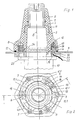
- a socket 1 of an inner cone plug coupling as is common for the connection of high-voltage cables in medium-voltage switchgear, has an insulating body 2 made of cast resin, in which an inner cone recess 3 is formed, which is open to an end face 4. At the opposite end, the inner cone recess 3 is followed by an axially identical plug contact part 5, which is to be connected to high-voltage internals in the encapsulated high-voltage device.
- Fastening fittings 6 and 7, which are axially parallel to the central axis 8 of the inner cone recess, are incorporated into the insulating body 2 from the end face 4. The fastening fittings are located on circular lines concentric to the opening of the inner cone recess, radially outside the inner cone recess.
- the end face 4 of the socket 1 lies in one plane on a wall 9 of a housing, within which there are high-voltage switchgear parts.
- this wall 9 is provided with a corresponding opening through which a cable connector 10 can be inserted from the outside.
- a hat-shaped field control body 11 is also attached to the high-voltage plug contact part 5, which is also embedded in the insulating body 2 and encompasses the adjacent section of the inner cone recess in a ring.
- an electrode 12 which is electrically insulated from it, is arranged in the region of the end face 4 and is arranged around the inner cone recess 3.
- this electrically insulated electrode 12 is formed from a plurality of partial electrodes 12.1 which are arranged in the circumferential direction between adjacent fastening fittings 6 and 7. These partial electrodes 12.1 are electrically connected to one another via a connecting line 13, the electrical connecting line 13 being embedded within the insulating body 2 in the insulating compound.
- the electrodes 12 and the connecting conductor 13 are preferably made of sieve or grid-like material, so that there is an intimate embedding that prevents the insulating compound from separating from the electrode or the connecting line during the shrinking process during the curing of the casting resin and forming dielectric defects will.
- the partial electrodes 12.1 can extend in the radial direction over the same area as the fastening fittings and, on the other hand, largely take up the space between adjacent fastening fittings 6, 7 and in the axial direction as far as into the insulating body 2 as the fittings 6, 7. This results in an extensive symmetrization of the electrical field, after which the gaps between adjacent fastening electrodes 6, 7 are then provided with electrically conductive parts which, at least approximately like the fastening fittings, are electrically almost at ground potential.
- the partial electrodes 12.1 are hood-shaped and are directed toward the field control body 11 with the rounded end. The rounding contributes to the favorable field distribution and forms a relatively large area compared to the field control body, the one corresponding high capacity value.
- the low capacitive resistance value achieved in this way enables the pending high voltage to be detected with relatively simple measuring devices.
- the connecting line 13, which also serves as an assembly aid for the positioning of the partial electrodes 12.1 in a casting mold, is flattened in the radial area of fastening fittings 6, deviating from the circular ring shape, and is provided on the flattened part with a small support insulator 14, which is fixed to the fastening fittings 6 concerned, around the Center electrodes 12.1 during the casting process of the insulating body 2.
- a connecting lug is attached to the connecting conductor 13, which protrudes into the space enclosed by the respective partial electrode 12 and is axially aligned is arranged to the inner cone recess in a recess 16 which is open to the end face 4.
- the connecting lug 15 also points with its free end to the end face 4.
- the respective terminal lug can be inserted into a holder corresponding to the recess 16, which is located within the casting mold which is used to produce the insulating body 2 with the internals.
- the connecting line 13 is located in the area which lies between the wall of the inner cone recess 3 and the fastening fittings 6, 7. In the axial direction, the connecting line 13 does not extend beyond the fastening fittings 6, 7.
- the socket 1 is fixed to the wall 9 with the interposition of a sealing ring 17.
- a spacer ring 18 is attached from the opposite side of the wall, which engages under the end face 4 with its radially inner part and with the radially outer part Part rests on the wall 9.
- This spacer ring 18 has an opening 19 which is aligned with the respective connecting lug 15 and merges into a groove 20 which extends radially outward. Through the opening 19, a plug 21 can thus be plugged into the terminal lug 15, from which an electrical line 22 can be guided through the groove 20 to a measuring device, not shown.
- a flange 23 of the cable connector 10 is seated on the spacer ring 18, a screw being able to be screwed into the associated fastening fitting 7 through the flange 23 and the spacer ring 18 and the wall 9.
- the socket 1 is fixed on the wall 9 via the spacer ring 18.
- the cable connector 10 has an electrical shield 24 which is guided in the outer jacket region and is connected to earth potential and extends axially beyond the connecting line 13 into the inner cone recess 3. It thus shields not only the connecting line 13 but also adjacent areas of the partial electrodes 12.1 from a conductor running axially within the cable connector 10.
- This conductor thus does not have a direct capacitive effect on the connecting line 13 or the relevant area of the partial electrodes 12.1, so that the voltage measured at the partial electrodes 12.1 is largely independent of whether the cable connector 10 is inserted into the socket 1 or not.
- the capacitive coupling thus takes place even when the cable connector 10 is inserted via the rounded ends of the partial electrodes 12.1 directly facing the field control body 11.
- the arrangement of the shield 24 in relation to the connecting line 13 and the partial electrodes 12.1 thus largely shields the electrical field generated by the cable connector 10 from the electrode 12.
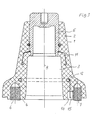
- a socket is shown in FIG. 3, in which the electrode 12 lies within the insulating body 2 in the electrical field area between the fastening fittings 6, 7 and the field control body 11.
- the electrode 12 is ring-shaped and is concentric with the axis 8 of the inner cone recess 3. It engages radially in the area that lies between the wall of the inner cone recess and a fastening fitting 7 that is displaced radially further outward.
- the electrode 12 extends into its radial area, but is axially spaced therefrom.
- the electrode 12 can preferably consist of a wire helix, between the individual windings of which the casting resin can penetrate and which does not lose the intimate connection with the casting resin when the casting resin composition shrinks during the curing process.
- the electrode 12 can also be connected to fastening fittings 6, 7 via adapted support insulators.
Landscapes
- Cable Accessories (AREA)
- Connector Housings Or Holding Contact Members (AREA)
- Details Of Connecting Devices For Male And Female Coupling (AREA)
Applications Claiming Priority (2)
| Application Number | Priority Date | Filing Date | Title |
|---|---|---|---|
| DE4009358 | 1990-03-23 | ||
| DE4009358A DE4009358C2 (de) | 1990-03-23 | 1990-03-23 | Steckbuchse |
Publications (3)
| Publication Number | Publication Date |
|---|---|
| EP0447910A2 true EP0447910A2 (fr) | 1991-09-25 |
| EP0447910A3 EP0447910A3 (en) | 1992-02-26 |
| EP0447910B1 EP0447910B1 (fr) | 1995-07-05 |
Family
ID=6402899
Family Applications (1)
| Application Number | Title | Priority Date | Filing Date |
|---|---|---|---|
| EP91103671A Expired - Lifetime EP0447910B1 (fr) | 1990-03-23 | 1991-03-11 | Contact femelle |
Country Status (5)
| Country | Link |
|---|---|
| EP (1) | EP0447910B1 (fr) |
| JP (1) | JPH05129047A (fr) |
| DE (2) | DE4009358C2 (fr) |
| FI (1) | FI104348B (fr) |
| NO (1) | NO302006B1 (fr) |
Cited By (1)
| Publication number | Priority date | Publication date | Assignee | Title |
|---|---|---|---|---|
| EP0572692A1 (fr) * | 1991-03-28 | 1993-12-08 | Karl Pfisterer Elektrotechnische Spezialartikel Gmbh & Co. Kg | Douille de connexion |
Families Citing this family (8)
| Publication number | Priority date | Publication date | Assignee | Title |
|---|---|---|---|---|
| DE4235044C2 (de) * | 1992-10-17 | 2002-06-20 | Alstom Sachsenwerk Gmbh | Steckbuchse |
| DE4312618A1 (de) * | 1993-04-19 | 1994-10-20 | Abb Patent Gmbh | Kabelsteckbuchse |
| DE19737426B4 (de) * | 1997-08-21 | 2005-05-04 | Siemens Ag | Steckerbuchse für Mittelspannungs-Schaltanlagen |
| DE19805068A1 (de) * | 1998-02-10 | 1999-08-12 | Abb Patent Gmbh | Kabelmuffe |
| CA2931170C (fr) | 2013-12-18 | 2022-05-03 | Basf Coatings Gmbh | Pates de pigment renfermant une dispersion aqueuse d'un copolymere |
| DE102014004284B4 (de) * | 2014-03-26 | 2019-11-14 | Lapp Insulators Gmbh | Hochspannungsdurchführung |
| DE102016205535A1 (de) | 2016-04-04 | 2017-10-05 | Siemens Aktiengesellschaft | Hochspannungsdurchführung |
| CN109451647B (zh) * | 2018-11-01 | 2020-08-07 | 中国人民解放军国防科技大学 | 一种强流二极管锥体陶瓷封装真空界面绝缘结构 |
Family Cites Families (8)
| Publication number | Priority date | Publication date | Assignee | Title |
|---|---|---|---|---|
| DE2732268C2 (de) * | 1977-07-16 | 1982-06-03 | Kabel- Und Lackdrahtfabriken Gmbh, 6800 Mannheim | Kabelendverschluß |
| DE2943080C2 (de) * | 1979-10-25 | 1982-04-08 | Karl Pfisterer Elektrotechnische Spezialartikel Gmbh & Co Kg, 7000 Stuttgart | Garnitur für das Ende eines Mittelspannungs- oder Hochspannungskabels |
| DE2915369B1 (de) * | 1979-04-14 | 1980-09-18 | Pfisterer Elektrotech Karl | Garnitur fuer das Ende eines Mittel- oder Hochspannungskabels |
| DE3110660C2 (de) * | 1981-03-19 | 1983-07-14 | Karl Pfisterer Elektrotechnische Spezialartikel Gmbh & Co Kg, 7000 Stuttgart | Garnitur für das Ende eines Mittelspannnungs- oder Hochspannunskabels |
| DE3247673C2 (de) * | 1982-12-23 | 1986-02-13 | Karl Pfisterer Elektrotechnische Spezialartikel Gmbh & Co Kg, 7000 Stuttgart | Steckerbuchse mit einem Feldsteuerkörper |
| DE3445905A1 (de) * | 1984-12-15 | 1986-06-26 | Karl Pfisterer Elektrotechnische Spezialartikel Gmbh & Co Kg, 7000 Stuttgart | Kupplung |
| DE3611462A1 (de) * | 1986-04-05 | 1987-10-15 | Pfisterer Elektrotech Karl | Verbindungsgarnitur fuer leiter eines mittelspannungs- oder hochspannungsnetzes |
| DE3644890A1 (de) * | 1986-04-05 | 1987-11-12 | Pfisterer Elektrotech Karl | Verbindungsgarnitur fuer leiter eines mittelspannungs- oder hochspannungsnetzes |
-
1990
- 1990-03-23 DE DE4009358A patent/DE4009358C2/de not_active Expired - Fee Related
-
1991
- 1991-03-11 EP EP91103671A patent/EP0447910B1/fr not_active Expired - Lifetime
- 1991-03-11 DE DE59105896T patent/DE59105896D1/de not_active Expired - Fee Related
- 1991-03-22 JP JP3058702A patent/JPH05129047A/ja active Pending
- 1991-03-22 NO NO911169A patent/NO302006B1/no unknown
- 1991-03-22 FI FI911400A patent/FI104348B/fi active
Cited By (1)
| Publication number | Priority date | Publication date | Assignee | Title |
|---|---|---|---|---|
| EP0572692A1 (fr) * | 1991-03-28 | 1993-12-08 | Karl Pfisterer Elektrotechnische Spezialartikel Gmbh & Co. Kg | Douille de connexion |
Also Published As
| Publication number | Publication date |
|---|---|
| FI911400A7 (fi) | 1991-09-24 |
| FI911400A0 (fi) | 1991-03-22 |
| EP0447910A3 (en) | 1992-02-26 |
| EP0447910B1 (fr) | 1995-07-05 |
| DE4009358C2 (de) | 1997-05-15 |
| JPH05129047A (ja) | 1993-05-25 |
| FI104348B1 (fi) | 1999-12-31 |
| DE59105896D1 (de) | 1995-08-10 |
| NO302006B1 (no) | 1998-01-05 |
| FI104348B (fi) | 1999-12-31 |
| NO911169D0 (no) | 1991-03-22 |
| NO911169L (no) | 1991-09-24 |
| DE4009358A1 (de) | 1991-09-26 |
Similar Documents
| Publication | Publication Date | Title |
|---|---|---|
| DE2348895C2 (de) | Verbindung für Starkstromkabel | |
| EP0671061B1 (fr) | Dispositif connecteur pour cable | |
| DE3544870A1 (de) | Zuendkerzenstecker | |
| DE4009358C2 (de) | Steckbuchse | |
| DE4435864A1 (de) | Garnitur in Form einer Durchführung oder einer Steckbuchse für Kabelstecker | |
| EP3893342B1 (fr) | Connecteur de câble | |
| EP0757796B1 (fr) | Dispositif pour raccorder un indicateur de tension a un detecteur | |
| DE2312897A1 (de) | Hochspannungs-verbindungsvorrichtung, insbesondere fuer geraetedurchfuehrungen | |
| EP0017953B1 (fr) | Garniture pour l'extrémité d'un câble moyenne tension ou haute tension | |
| DE3540547A1 (de) | Hochspannungsstromwandler und verfahren zur herstellung eines derartigen hochspannungsstromwandlers | |
| DE3935360C2 (fr) | ||
| DE2410625A1 (de) | Hochspannungs-verbindungsvorrichtung | |
| DE69803896T2 (de) | Verfahren zum Verbinden von elektrischen Kabeln mit elektrischen Geräten, insbesondere mit Kraftfahrzeuganlasser | |
| EP0163053B1 (fr) | Dérivateur de surtensions | |
| EP0459250B1 (fr) | Garniture d'extrémité de câble | |
| EP1950770A2 (fr) | Isolateur | |
| DE3538193C2 (fr) | ||
| DE4234461A1 (de) | Prüfadapter insbesondere für Mittelspannungsschaltanlagen | |
| DE2943080C2 (de) | Garnitur für das Ende eines Mittelspannungs- oder Hochspannungskabels | |
| DE2609079C2 (de) | Kabeleinführung | |
| DE2740232C3 (de) | Verbindungsmuffe | |
| WO1992016953A1 (fr) | Composant pour installations d'alimentation en energie de haute tension | |
| DE3619789C1 (en) | Connecting device which can be connected to a bolt | |
| DE4235044C2 (de) | Steckbuchse | |
| WO2026053022A1 (fr) | Dispositif enfichable et appareil de connexion enfichable comprenant un tel dispositif enfichable |
Legal Events
| Date | Code | Title | Description |
|---|---|---|---|
| PUAI | Public reference made under article 153(3) epc to a published international application that has entered the european phase |
Free format text: ORIGINAL CODE: 0009012 |
|
| AK | Designated contracting states |
Kind code of ref document: A2 Designated state(s): DE FR GB IT |
|
| PUAL | Search report despatched |
Free format text: ORIGINAL CODE: 0009013 |
|
| AK | Designated contracting states |
Kind code of ref document: A3 Designated state(s): DE FR GB IT |
|
| RAP1 | Party data changed (applicant data changed or rights of an application transferred) |
Owner name: AEG SACHSENWERK GMBH |
|
| 17P | Request for examination filed |
Effective date: 19920630 |
|
| 17Q | First examination report despatched |
Effective date: 19940415 |
|
| GRAA | (expected) grant |
Free format text: ORIGINAL CODE: 0009210 |
|
| AK | Designated contracting states |
Kind code of ref document: B1 Designated state(s): DE FR GB IT |
|
| REF | Corresponds to: |
Ref document number: 59105896 Country of ref document: DE Date of ref document: 19950810 |
|
| ET | Fr: translation filed | ||
| GBT | Gb: translation of ep patent filed (gb section 77(6)(a)/1977) |
Effective date: 19950829 |
|
| ITF | It: translation for a ep patent filed | ||
| PLBE | No opposition filed within time limit |
Free format text: ORIGINAL CODE: 0009261 |
|
| STAA | Information on the status of an ep patent application or granted ep patent |
Free format text: STATUS: NO OPPOSITION FILED WITHIN TIME LIMIT |
|
| 26N | No opposition filed | ||
| PGFP | Annual fee paid to national office [announced via postgrant information from national office to epo] |
Ref country code: GB Payment date: 19990226 Year of fee payment: 9 |
|
| PGFP | Annual fee paid to national office [announced via postgrant information from national office to epo] |
Ref country code: FR Payment date: 19990318 Year of fee payment: 9 |
|
| PGFP | Annual fee paid to national office [announced via postgrant information from national office to epo] |
Ref country code: DE Payment date: 19990529 Year of fee payment: 9 |
|
| PG25 | Lapsed in a contracting state [announced via postgrant information from national office to epo] |
Ref country code: GB Free format text: LAPSE BECAUSE OF NON-PAYMENT OF DUE FEES Effective date: 20000311 |
|
| GBPC | Gb: european patent ceased through non-payment of renewal fee |
Effective date: 20000311 |
|
| PG25 | Lapsed in a contracting state [announced via postgrant information from national office to epo] |
Ref country code: FR Free format text: LAPSE BECAUSE OF NON-PAYMENT OF DUE FEES Effective date: 20001130 |
|
| REG | Reference to a national code |
Ref country code: FR Ref legal event code: ST |
|
| PG25 | Lapsed in a contracting state [announced via postgrant information from national office to epo] |
Ref country code: DE Free format text: LAPSE BECAUSE OF NON-PAYMENT OF DUE FEES Effective date: 20010103 |
|
| PG25 | Lapsed in a contracting state [announced via postgrant information from national office to epo] |
Ref country code: IT Free format text: LAPSE BECAUSE OF NON-PAYMENT OF DUE FEES;WARNING: LAPSES OF ITALIAN PATENTS WITH EFFECTIVE DATE BEFORE 2007 MAY HAVE OCCURRED AT ANY TIME BEFORE 2007. THE CORRECT EFFECTIVE DATE MAY BE DIFFERENT FROM THE ONE RECORDED. Effective date: 20050311 |