EP0447941A1 - Frein électromagnétique - Google Patents
Frein électromagnétique Download PDFInfo
- Publication number
- EP0447941A1 EP0447941A1 EP91103856A EP91103856A EP0447941A1 EP 0447941 A1 EP0447941 A1 EP 0447941A1 EP 91103856 A EP91103856 A EP 91103856A EP 91103856 A EP91103856 A EP 91103856A EP 0447941 A1 EP0447941 A1 EP 0447941A1
- Authority
- EP
- European Patent Office
- Prior art keywords
- brake
- anchor
- magnet
- spring
- threads
- Prior art date
- Legal status (The legal status is an assumption and is not a legal conclusion. Google has not performed a legal analysis and makes no representation as to the accuracy of the status listed.)
- Granted
Links
- 238000010276 construction Methods 0.000 claims description 7
- 229910000831 Steel Inorganic materials 0.000 description 3
- 230000033001 locomotion Effects 0.000 description 3
- 239000010959 steel Substances 0.000 description 3
- 238000004140 cleaning Methods 0.000 description 2
- 239000004020 conductor Substances 0.000 description 2
- 230000003247 decreasing effect Effects 0.000 description 2
- 238000004804 winding Methods 0.000 description 2
- NMFHJNAPXOMSRX-PUPDPRJKSA-N [(1r)-3-(3,4-dimethoxyphenyl)-1-[3-(2-morpholin-4-ylethoxy)phenyl]propyl] (2s)-1-[(2s)-2-(3,4,5-trimethoxyphenyl)butanoyl]piperidine-2-carboxylate Chemical compound C([C@@H](OC(=O)[C@@H]1CCCCN1C(=O)[C@@H](CC)C=1C=C(OC)C(OC)=C(OC)C=1)C=1C=C(OCCN2CCOCC2)C=CC=1)CC1=CC=C(OC)C(OC)=C1 NMFHJNAPXOMSRX-PUPDPRJKSA-N 0.000 description 1
- 238000005452 bending Methods 0.000 description 1
- 239000000428 dust Substances 0.000 description 1
- 230000000694 effects Effects 0.000 description 1
- 238000003754 machining Methods 0.000 description 1
- 238000012423 maintenance Methods 0.000 description 1
- 230000000750 progressive effect Effects 0.000 description 1
- 238000007789 sealing Methods 0.000 description 1
Images


Classifications
-
- H—ELECTRICITY
- H02—GENERATION; CONVERSION OR DISTRIBUTION OF ELECTRIC POWER
- H02K—DYNAMO-ELECTRIC MACHINES
- H02K7/00—Arrangements for handling mechanical energy structurally associated with dynamo-electric machines, e.g. structural association with mechanical driving motors or auxiliary dynamo-electric machines
- H02K7/10—Structural association with clutches, brakes, gears, pulleys or mechanical starters
- H02K7/102—Structural association with clutches, brakes, gears, pulleys or mechanical starters with friction brakes
- H02K7/1021—Magnetically influenced friction brakes
- H02K7/1023—Magnetically influenced friction brakes using electromagnets
- H02K7/1025—Magnetically influenced friction brakes using electromagnets using axial electromagnets with generally annular air gap
-
- F—MECHANICAL ENGINEERING; LIGHTING; HEATING; WEAPONS; BLASTING
- F16—ENGINEERING ELEMENTS AND UNITS; GENERAL MEASURES FOR PRODUCING AND MAINTAINING EFFECTIVE FUNCTIONING OF MACHINES OR INSTALLATIONS; THERMAL INSULATION IN GENERAL
- F16D—COUPLINGS FOR TRANSMITTING ROTATION; CLUTCHES; BRAKES
- F16D55/00—Brakes with substantially-radial braking surfaces pressed together in axial direction, e.g. disc brakes
- F16D55/24—Brakes with substantially-radial braking surfaces pressed together in axial direction, e.g. disc brakes with a plurality of axially-movable discs, lamellae, or pads, pressed from one side towards an axially-located member
- F16D55/26—Brakes with substantially-radial braking surfaces pressed together in axial direction, e.g. disc brakes with a plurality of axially-movable discs, lamellae, or pads, pressed from one side towards an axially-located member without self-tightening action
- F16D55/28—Brakes with only one rotating disc
-
- F—MECHANICAL ENGINEERING; LIGHTING; HEATING; WEAPONS; BLASTING
- F16—ENGINEERING ELEMENTS AND UNITS; GENERAL MEASURES FOR PRODUCING AND MAINTAINING EFFECTIVE FUNCTIONING OF MACHINES OR INSTALLATIONS; THERMAL INSULATION IN GENERAL
- F16D—COUPLINGS FOR TRANSMITTING ROTATION; CLUTCHES; BRAKES
- F16D59/00—Self-acting brakes, e.g. coming into operation at a predetermined speed
- F16D59/02—Self-acting brakes, e.g. coming into operation at a predetermined speed spring-loaded and adapted to be released by mechanical, fluid, or electromagnetic means
-
- F—MECHANICAL ENGINEERING; LIGHTING; HEATING; WEAPONS; BLASTING
- F16—ENGINEERING ELEMENTS AND UNITS; GENERAL MEASURES FOR PRODUCING AND MAINTAINING EFFECTIVE FUNCTIONING OF MACHINES OR INSTALLATIONS; THERMAL INSULATION IN GENERAL
- F16D—COUPLINGS FOR TRANSMITTING ROTATION; CLUTCHES; BRAKES
- F16D65/00—Parts or details
- F16D65/38—Slack adjusters
- F16D65/40—Slack adjusters mechanical
- F16D65/52—Slack adjusters mechanical self-acting in one direction for adjusting excessive play
- F16D65/56—Slack adjusters mechanical self-acting in one direction for adjusting excessive play with screw-thread and nut
-
- H—ELECTRICITY
- H02—GENERATION; CONVERSION OR DISTRIBUTION OF ELECTRIC POWER
- H02K—DYNAMO-ELECTRIC MACHINES
- H02K7/00—Arrangements for handling mechanical energy structurally associated with dynamo-electric machines, e.g. structural association with mechanical driving motors or auxiliary dynamo-electric machines
- H02K7/10—Structural association with clutches, brakes, gears, pulleys or mechanical starters
- H02K7/102—Structural association with clutches, brakes, gears, pulleys or mechanical starters with friction brakes
- H02K7/1021—Magnetically influenced friction brakes
- H02K7/1023—Magnetically influenced friction brakes using electromagnets
-
- F—MECHANICAL ENGINEERING; LIGHTING; HEATING; WEAPONS; BLASTING
- F16—ENGINEERING ELEMENTS AND UNITS; GENERAL MEASURES FOR PRODUCING AND MAINTAINING EFFECTIVE FUNCTIONING OF MACHINES OR INSTALLATIONS; THERMAL INSULATION IN GENERAL
- F16D—COUPLINGS FOR TRANSMITTING ROTATION; CLUTCHES; BRAKES
- F16D55/00—Brakes with substantially-radial braking surfaces pressed together in axial direction, e.g. disc brakes
- F16D2055/0004—Parts or details of disc brakes
- F16D2055/0058—Fully lined, i.e. braking surface extending over the entire disc circumference
-
- F—MECHANICAL ENGINEERING; LIGHTING; HEATING; WEAPONS; BLASTING
- F16—ENGINEERING ELEMENTS AND UNITS; GENERAL MEASURES FOR PRODUCING AND MAINTAINING EFFECTIVE FUNCTIONING OF MACHINES OR INSTALLATIONS; THERMAL INSULATION IN GENERAL
- F16D—COUPLINGS FOR TRANSMITTING ROTATION; CLUTCHES; BRAKES
- F16D2121/00—Type of actuator operation force
- F16D2121/18—Electric or magnetic
- F16D2121/20—Electric or magnetic using electromagnets
- F16D2121/22—Electric or magnetic using electromagnets for releasing a normally applied brake
Definitions
- the present invention relates to an electromagnetic brake as defined in the introductory part of claim 1.
- FI publication 75653 proposes an electromagnetic disc brake in which, when the brake is closed, a constant gap between the electromagnet coil and the anchor plate is maintained by means of a stepless adjusting device provided with balls running in groove tracks at that end where the electromagnet frame is located or with a wedge placed between the frame and the electromagnet coil, said wedge moving downwards due to its own weight, thereby adjusting the size of the air gap.
- the object of the present invention is to achieve improved adjustment of the air gap in an electromagnetic brake.
- the features characteristic of the electromagnetic brake of the invention are presented in the claims.
- the invention achieves a brake with a constant air gap, which means that a smaller brake magnet can be used. Moreover, the brake permits the presence of a large number of tolerances, and the working clearance can be adjusted by means of pins. The adjustment is even and simple and remains functional at least as long as the wear surfaces of the brake last.
- Fig. 1 presents a disc brake constructed as provided by the invention.
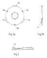
- Figs. 2a and 2b present the anchor plate in side view and in end view.
- Fig. 3 presents an adjusting plate.
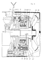
- Fig. 4 represents another disc brake constructed according to a preferred embodiment of the invention.
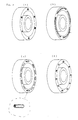
- Fig. 5a till 5d present magnet houses with alternative elastic components in perspective views.
- Fig. 6 presents a detail from the threads connection between brake housing and anchor plate in a certain situation at an enlarged scale.
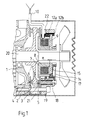
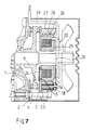
- Fig. 7 presents another disc brake constructed as provided by the invention.
- Fig. 8 presents a drum brake constructed as provided by the invention.
- Fig. 1 represents the working brake of an electric motor used e.g. as a hoisting motor in a crane, in which the brake magnet air gap is self-adjusting.
- the brake comprises an end shield 1, to which one of the friction plates 2 is attached. Between the friction plates 2 and 3, which are provided with linings 4 and 5, is a brake wheel 6.
- One 3 of the friction plates is coupled with an electromagnet, which consists of a magnet housing 7 fixed to the friction plate and a winding 8 inside it. The groove of the magnet housing points away from the motor in the direction where the anchor plate 9 is located.
- the anchor plate is provided with three pitched vanes 11a- 11c as illustrated by Figs. 2a and 2b, and it is disposed in a flat thread with three pitched tracks by placing it between two identical adjustment rings 12a and 12b provided with three-track flat thread surfaces 13 as illustrated by Fig. 3.
- the anchor plate is rotated by means of a coiled spring 14 wound about a spring box 15 located around the cylindrical extension of the anchor plate 9.
- the anchor plate 9 is provided with holes 16a - 16c accommodating pins 17 loaded by a pre-tensioned spring, e.g. a cup spring.
- the pins 17 protrude from the anchor plate 9 on the side facing the magnet by a distance equalling the working clearance e.
- the magnet-friction plate assembly When no current is flowing in the brake magnet coil, the magnet-friction plate assembly is pushed against the brake wheel 6 by brake springs 18, which are backed by the brake housing 19, and the braking action is started. At this instant, there is a certain working clearance e between the magnet 7, 8 and the anchor plate. This clearance equals the length of the protruding parts of the pins 17 minus the anchor plate tolerance. As the braking surfaces get thinner due to wear, the air gap between the magnet 7, 8 and anchor 9 increases. Consequently, the anchor plate 9 is rotated in its thread by coiled spring 14 until the pin ends meet the magnet. The force of the coiled spring does not exceed the force of the cup spring pressing the pins out through the anchor plate 9. Thus, the adjusting motion is stopped as the pin ends meet the magnet 7, 8, and the wear of the brake surfaces has been compensated. The compensation is stepless.
- the brake is provided with a circular spring 22 placed in front of the foremost adjustment ring 12a.
- the outer surface of the anchor 9 is provided with a thread 11' which engages a corresponding thread 12' provided in the brake housing 19. Therefore, the anchor 9 is able to rotate in the thread 12' in the brake housing 19.
- the brake is provided with a coiled spring 14 placed in a separate spring-box 15 provided in the end face of the anchor.
- the spring box protects the spring box against entanglement and accidental unwinding as well as against hitting other parts of the brake.
- the coil spring rotates the anchor until the latter touches an O-ring 16' mounted in a groove in the end face of the magnet.
- the joint between the magnet and one of the friction plates has no play. This is achieved by "calibrating" the thickness of the friction plate.
- the calibration is implemented by bending small collets 17' outwards from the plane of the plate. Calibration is necessary because the thickness of standard steel plate varies too much. For instance, in the case of 4 mm hot-rolled steel plate, the allowed thickness variation is +0.6/- 0.4 mm (DIN 1543). Without calibration of plate thickness, the axial space for the friction plate on the outer surface of the magnet should be determined according to the largest permitted plate thickness. In the worst case, this would lead to an axial clearance as large as 1 mm (in the case of minimum allowed plate thickness).
- the O-ring construction prevents overcompensation in three ways:
- Fig. 5a In the construction of Fig. 4, instead of using an O-ring also some other elastic components may be used according to Fig. 5a - 5d, but with minor chance of preventing over-compensation. Those components are for instance elastic pins (Fig. 5a), bands (Fig. 5b), bars (Fig. 5c) or balls (Fig. 5d).
- one 23 of the friction plates acts as an anchor plate, with spring elements 24 pressing the pins 17.
- the groove of the magnet housing 25 points towards the motor.
- the magnet housing is provided with an external thread 26 fitting into the internal thread 28 of the counterpart 27.
- the conductor 29 passes round the axle 20 inside a protecting shield 30.
- the brake housing thread matching the anchor plate thread (Fig. 4) or the magnet housing thread (Fig. 7) is not continous but is divided into four parts. Regardless of the anchor or magnet housing position, the midpoints of these parts are always at an angle of 45° relative to the horizontal and vertical axes. This arrangement allows the dust and dirt accumulated in the threads to fall down from the thread. Thus the threads in the brake housing are self-cleaning. The self-cleaning effect is promoted by the axial anchor motion occurring each time when power is switched on/off.
- the outer end of the coiled spring 14 can be fastened on the brake housing 19 or 27 respectively at a selectable position at 15° distances, the brake housing being provided with holes or cut-outs to allow the spring end to be fastened with a screw.
- the brake housing 19 is provided with a cut-out for the brake magnet supply cable 10. This cut-out accommodates a cable seal which, besides sealing the cable, also prevents the magnet from rotating, which is necessary to ensure correct operation of the adjustment and to protect the cable against damage by attrition. These holes and cut-outs allow auxiliary equipment and attachments to be fastened without extra machining.
- the brake housing is provided with lugs (not shown) which
- the brake housing 19 comprises sleeves 30' (Fig. 4) placed inside the brake springs 18 and provided with an internal thread. By inserting threaded bolts through corresponding holes 31' in the brake housing and screwing them into the sleeves, the brake springs can be prevented from being released when the brake is dismantled e.g. in connection with maintenance operations.
- Fig. 8 presents an automatically adjusted drum brake provided with brake arms 32 actuated by push/pull rods 31.
- the ends of the brake arms are provided with brake linings 33 which engage the brake wheel 34 during braking.
- Brake springs 35 provided between the frame 36 and stoppers 37 apply a pressure to the push/pull rods 31, with the result that the width of the air gap between the anchor 38 and the magnet 39, 40 tends to increase due to the wear of the brake linings.
- the anchor 38 is connected to the push/pull rods by threads 41, 42, and it is also subject to the force of a coiled spring 43. When the power to the brake magnet is disconnected, the coiled springs cause the anchors 38 to rotate on the threads 42 of the push/pull rods until the spring-loaded (cup springs 44) pins 45 meet the magnet surface.
- Guide bushings 46 ensure that the anchor faces are always aligned in a direction sufficiently close to parallel with the corresponding magnet surfaces.
- the adjusting threads 41, 42 must be self-retaining. As can be seen from Fig. 5, the two halves of the drum brake are symmetrical.
Landscapes
- Engineering & Computer Science (AREA)
- General Engineering & Computer Science (AREA)
- Physics & Mathematics (AREA)
- Electromagnetism (AREA)
- Mechanical Engineering (AREA)
- Power Engineering (AREA)
- Braking Arrangements (AREA)
Applications Claiming Priority (2)
| Application Number | Priority Date | Filing Date | Title |
|---|---|---|---|
| FI901247A FI901247A7 (fi) | 1990-03-13 | 1990-03-13 | Elektromagnetisk broms. |
| FI901247 | 1990-03-13 |
Publications (2)
| Publication Number | Publication Date |
|---|---|
| EP0447941A1 true EP0447941A1 (fr) | 1991-09-25 |
| EP0447941B1 EP0447941B1 (fr) | 1994-06-08 |
Family
ID=8530055
Family Applications (1)
| Application Number | Title | Priority Date | Filing Date |
|---|---|---|---|
| EP91103856A Expired - Lifetime EP0447941B1 (fr) | 1990-03-13 | 1991-03-13 | Frein électromagnétique |
Country Status (5)
| Country | Link |
|---|---|
| US (3) | US5368138A (fr) |
| EP (1) | EP0447941B1 (fr) |
| DE (1) | DE69102323T2 (fr) |
| ES (1) | ES2055479T3 (fr) |
| FI (1) | FI901247A7 (fr) |
Cited By (5)
| Publication number | Priority date | Publication date | Assignee | Title |
|---|---|---|---|---|
| DE4408584C2 (de) * | 1994-03-14 | 2000-04-20 | Stahl R Foerdertech Gmbh | Elektrokettenzug mit selbständiger Bremse |
| ES2168940A1 (es) * | 2000-02-04 | 2002-06-16 | Univ Catalunya Politecnica | Mecanismo de autorregulacion del entrehierro en los sistemas de actuacion electromagnetica. |
| WO2008141998A1 (fr) * | 2007-05-21 | 2008-11-27 | Siemens Aktiengesellschaft | Unité de freinage pour machine électrique, flasque comprenant une unité de freinage de ce type et machine électrique |
| CN104455094A (zh) * | 2014-12-07 | 2015-03-25 | 遵义市宝海农用物资研发有限公司 | 塑料成型偏心带式制动器 |
| WO2017108527A1 (fr) * | 2015-12-23 | 2017-06-29 | Moteurs Leroy-Somer | Frein pour machine electrique tournante |
Families Citing this family (23)
| Publication number | Priority date | Publication date | Assignee | Title |
|---|---|---|---|---|
| EP0796814B1 (fr) * | 1996-03-22 | 2004-09-22 | Sanyo Kogyo Co., Ltd. | Frein pour appareil de levage |
| FR2755084B1 (fr) * | 1996-10-25 | 1998-12-11 | Warner France | Dispositif de freinage a couple de freinage variable |
| DE19711851B4 (de) * | 1997-03-21 | 2005-09-22 | Continental Teves Ag & Co. Ohg | Bremsaktuator mit Feststellbremse für eine elektrische Bremsanlage |
| US6161659A (en) * | 1998-09-29 | 2000-12-19 | Inertia Dynamics, Inc. | Electromagnetic disk brake with rubber friction disk braking surface |
| US6125975A (en) * | 1998-11-17 | 2000-10-03 | Inertia Dynamics | Sealed electromagnetic brake |
| FI106255B (fi) * | 1998-12-23 | 2000-12-29 | Kone Corp | Vetopyörähissin pitojarru |
| JP2000220674A (ja) * | 1999-02-01 | 2000-08-08 | Tsubakimoto Chain Co | 無励磁作動型電磁ブレーキの消音装置 |
| JP2000220666A (ja) * | 1999-02-01 | 2000-08-08 | Tsubakimoto Chain Co | 無励磁作動型電磁ブレーキの消音装置 |
| DE19943209C2 (de) * | 1999-09-09 | 2002-01-24 | Walterscheid Gmbh Gkn | Kupplungsanordnung für landwirtschaftliche Geräte |
| US6336530B1 (en) * | 2000-04-07 | 2002-01-08 | Timothy L. Hottle | Vehicle brake assembly |
| US6481542B2 (en) | 2001-02-19 | 2002-11-19 | Meritor Heavy Vehicle Systems, Llc. | Brake adjuster |
| KR100794767B1 (ko) * | 2006-04-15 | 2008-01-15 | 한국고벨주식회사 | 로드셀을 이용한 디씨 디스크브레이크 제동력 감지장치 및그 방법 |
| DE102010017889A1 (de) * | 2010-04-21 | 2011-10-27 | Ortlinghaus-Werke Gmbh | Regelbare Bremse |
| FI123568B (fi) * | 2011-03-24 | 2013-07-15 | Kone Corp | Sähkömagneettinen jarru |
| JP5579111B2 (ja) * | 2011-03-24 | 2014-08-27 | 株式会社キトー | 無励磁作動ブレーキを備えた巻上機 |
| CN102437681A (zh) * | 2011-10-10 | 2012-05-02 | 浙江劲野科技有限公司 | 一种风力发电机安全自动制动装置 |
| DE102012010790B4 (de) * | 2012-06-01 | 2017-05-18 | Sew-Eurodrive Gmbh & Co Kg | Bremse, insbesondere elektromagnetisch betätigbare Bremse |
| CN106451907B (zh) * | 2016-08-25 | 2018-12-18 | 常州市松泽电器有限公司 | 粮筒转向电机 |
| CN111687879B (zh) * | 2020-06-18 | 2021-05-25 | 敬科(深圳)机器人科技有限公司 | 一种协作机器人模块化关节 |
| CN113685454A (zh) * | 2021-09-01 | 2021-11-23 | 向雨 | 离合器 |
| JP7694449B2 (ja) * | 2022-04-25 | 2025-06-18 | 株式会社豊田自動織機 | 電磁ブレーキ装置 |
| DE102024000153A1 (de) * | 2024-01-19 | 2025-07-24 | Chr. Mayr Gmbh + Co. Kg | Mehrteilige Dämpferstruktur mit Biegering |
| CN120855738B (zh) * | 2025-09-24 | 2025-11-25 | 德州恒力电机有限责任公司 | 一种基于直驱电机的自补偿刹车机构 |
Citations (4)
| Publication number | Priority date | Publication date | Assignee | Title |
|---|---|---|---|---|
| CH396531A (de) * | 1960-08-23 | 1965-07-31 | Inventio Ag | Selbsttätig und stufenlos wirkende Nachstellvorrichtung für eine entgegen der Kraft einer Bremsdruckfeder durch einen Elektromotor lüftbare Aussenbackenbremse |
| DE1914469B1 (de) * | 1969-03-21 | 1970-07-02 | Baumueller Gmbh A | Nachstellvorrichtung fuer das Lueftspiel einer durch Federkraft betaetigten und elektromagnetisch geluefteten Einscheibenbremse fuer Motoren,insbesondere Elektromotoren |
| DE1675157B1 (de) * | 1968-01-23 | 1971-07-01 | Licentia Gmbh | Reibungsbremse mit selbsttaetigem Verschleissausgleich |
| US3613838A (en) * | 1969-04-21 | 1971-10-19 | Hans Lanze Kg Maschf | Automatic adjusting device for clutches and brakes |
Family Cites Families (6)
| Publication number | Priority date | Publication date | Assignee | Title |
|---|---|---|---|---|
| US2970681A (en) * | 1959-02-20 | 1961-02-07 | Warner Electric Brake & Clutch | Wear adjuster for magnetic friction devices |
| US3575268A (en) * | 1969-09-08 | 1971-04-20 | Isuzu Motors Ltd | Automatic clearance-adjusting means for disc brake |
| US4175650A (en) * | 1977-03-11 | 1979-11-27 | Facet Enterprises, Inc. | Self-adjusting electromagnetic disc clutch |
| US4582187A (en) * | 1981-12-30 | 1986-04-15 | Facet Enterprises Inc. | Self-adjusting electromagnetic cone brake with overrunning adjustment assembly |
| US4966255A (en) * | 1988-11-16 | 1990-10-30 | Reliance Electric Industrial Company | Automatic wear compensator for electromagnetic brake |
| DE3870882D1 (de) * | 1988-12-14 | 1992-06-11 | Mayr Christian Gmbh & Co Kg | Selbsttaetige nachstellvorrichtung fuer elektromagnetisch betaetigte kupplungs- und/oder bremsaggregate. |
-
1990
- 1990-03-13 FI FI901247A patent/FI901247A7/fi not_active Application Discontinuation
-
1991
- 1991-03-13 ES ES91103856T patent/ES2055479T3/es not_active Expired - Lifetime
- 1991-03-13 DE DE69102323T patent/DE69102323T2/de not_active Expired - Lifetime
- 1991-03-13 EP EP91103856A patent/EP0447941B1/fr not_active Expired - Lifetime
-
1992
- 1992-11-13 US US07/976,007 patent/US5368138A/en not_active Expired - Lifetime
-
1994
- 1994-06-03 US US08/253,945 patent/US5433297A/en not_active Expired - Lifetime
- 1994-06-03 US US08/253,692 patent/US5415253A/en not_active Expired - Lifetime
Patent Citations (4)
| Publication number | Priority date | Publication date | Assignee | Title |
|---|---|---|---|---|
| CH396531A (de) * | 1960-08-23 | 1965-07-31 | Inventio Ag | Selbsttätig und stufenlos wirkende Nachstellvorrichtung für eine entgegen der Kraft einer Bremsdruckfeder durch einen Elektromotor lüftbare Aussenbackenbremse |
| DE1675157B1 (de) * | 1968-01-23 | 1971-07-01 | Licentia Gmbh | Reibungsbremse mit selbsttaetigem Verschleissausgleich |
| DE1914469B1 (de) * | 1969-03-21 | 1970-07-02 | Baumueller Gmbh A | Nachstellvorrichtung fuer das Lueftspiel einer durch Federkraft betaetigten und elektromagnetisch geluefteten Einscheibenbremse fuer Motoren,insbesondere Elektromotoren |
| US3613838A (en) * | 1969-04-21 | 1971-10-19 | Hans Lanze Kg Maschf | Automatic adjusting device for clutches and brakes |
Cited By (7)
| Publication number | Priority date | Publication date | Assignee | Title |
|---|---|---|---|---|
| DE4408584C2 (de) * | 1994-03-14 | 2000-04-20 | Stahl R Foerdertech Gmbh | Elektrokettenzug mit selbständiger Bremse |
| ES2168940A1 (es) * | 2000-02-04 | 2002-06-16 | Univ Catalunya Politecnica | Mecanismo de autorregulacion del entrehierro en los sistemas de actuacion electromagnetica. |
| WO2008141998A1 (fr) * | 2007-05-21 | 2008-11-27 | Siemens Aktiengesellschaft | Unité de freinage pour machine électrique, flasque comprenant une unité de freinage de ce type et machine électrique |
| CN104455094A (zh) * | 2014-12-07 | 2015-03-25 | 遵义市宝海农用物资研发有限公司 | 塑料成型偏心带式制动器 |
| CN104455094B (zh) * | 2014-12-07 | 2017-02-22 | 遵义市宝海农用物资研发有限公司 | 塑料成型偏心带式制动器 |
| WO2017108527A1 (fr) * | 2015-12-23 | 2017-06-29 | Moteurs Leroy-Somer | Frein pour machine electrique tournante |
| FR3046307A1 (fr) * | 2015-12-23 | 2017-06-30 | Moteurs Leroy-Somer | Frein pour machine electrique tournante |
Also Published As
| Publication number | Publication date |
|---|---|
| US5415253A (en) | 1995-05-16 |
| US5433297A (en) | 1995-07-18 |
| DE69102323T2 (de) | 1994-09-15 |
| EP0447941B1 (fr) | 1994-06-08 |
| US5368138A (en) | 1994-11-29 |
| DE69102323D1 (de) | 1994-07-14 |
| FI901247A0 (fi) | 1990-03-13 |
| FI901247A7 (fi) | 1991-09-14 |
| ES2055479T3 (es) | 1994-08-16 |
Similar Documents
| Publication | Publication Date | Title |
|---|---|---|
| EP0447941B1 (fr) | Frein électromagnétique | |
| US5186286A (en) | Electromagnetic brake | |
| US20020100646A1 (en) | Elevator brake assembly | |
| US5186287A (en) | Simplified motor brake | |
| GB2026110A (en) | Electromagnetically releasable spring-actuated brake | |
| US4966255A (en) | Automatic wear compensator for electromagnetic brake | |
| US4226307A (en) | Apparatus for taking up wear in a brake and brake utilizing this apparatus | |
| US5090522A (en) | Brake actuating apparatus | |
| CN120819590B (zh) | 一种方便拆装的高稳定性电磁制动器 | |
| US5497860A (en) | Electromagnetic brake with improved magnet structure | |
| EP1374368B1 (fr) | Combinaison accouplement et frein | |
| JP7277588B2 (ja) | ブレーキアセンブリの遊びを調整するための方法およびブレーキアセンブリ | |
| US12590614B2 (en) | Floating caliper brake having two metal sections and one elastomer section | |
| JPH027296Y2 (fr) | ||
| FI113107B (fi) | Sähkömagneettinen jarru | |
| JPS59739B2 (ja) | 摩擦式電磁連結装置 | |
| CN120785132B (zh) | 一种力矩电机及其驱动结构 | |
| CN114448164B (zh) | 一种电机制动装置及外转子电机 | |
| US3917035A (en) | Electric brake adjuster | |
| CA1289085C (fr) | Frein a reprise automatique du jeu | |
| CN113700777B (zh) | 制动器 | |
| JPS595234Y2 (ja) | 電磁クラツチ・ブレ−キの自動空隙調整装置 | |
| SU1504403A1 (ru) | Дисковый электромагнитный тормоз | |
| CN117366132A (zh) | 制动盘组件、制动盘的安装方法、制动器及其应用 | |
| JPS633472Y2 (fr) |
Legal Events
| Date | Code | Title | Description |
|---|---|---|---|
| PUAI | Public reference made under article 153(3) epc to a published international application that has entered the european phase |
Free format text: ORIGINAL CODE: 0009012 |
|
| AK | Designated contracting states |
Kind code of ref document: A1 Designated state(s): DE ES FR GB IT |
|
| 17P | Request for examination filed |
Effective date: 19920227 |
|
| 17Q | First examination report despatched |
Effective date: 19930927 |
|
| GRAA | (expected) grant |
Free format text: ORIGINAL CODE: 0009210 |
|
| AK | Designated contracting states |
Kind code of ref document: B1 Designated state(s): DE ES FR GB IT |
|
| REF | Corresponds to: |
Ref document number: 69102323 Country of ref document: DE Date of ref document: 19940714 |
|
| ITF | It: translation for a ep patent filed | ||
| REG | Reference to a national code |
Ref country code: ES Ref legal event code: FG2A Ref document number: 2055479 Country of ref document: ES Kind code of ref document: T3 |
|
| ET | Fr: translation filed | ||
| PLBE | No opposition filed within time limit |
Free format text: ORIGINAL CODE: 0009261 |
|
| STAA | Information on the status of an ep patent application or granted ep patent |
Free format text: STATUS: NO OPPOSITION FILED WITHIN TIME LIMIT |
|
| 26N | No opposition filed | ||
| REG | Reference to a national code |
Ref country code: GB Ref legal event code: IF02 |
|
| PGFP | Annual fee paid to national office [announced via postgrant information from national office to epo] |
Ref country code: ES Payment date: 20100322 Year of fee payment: 20 |
|
| PGFP | Annual fee paid to national office [announced via postgrant information from national office to epo] |
Ref country code: GB Payment date: 20100324 Year of fee payment: 20 |
|
| PGFP | Annual fee paid to national office [announced via postgrant information from national office to epo] |
Ref country code: FR Payment date: 20100416 Year of fee payment: 20 |
|
| PGFP | Annual fee paid to national office [announced via postgrant information from national office to epo] |
Ref country code: IT Payment date: 20100330 Year of fee payment: 20 Ref country code: DE Payment date: 20100329 Year of fee payment: 20 |
|
| REG | Reference to a national code |
Ref country code: DE Ref legal event code: R071 Ref document number: 69102323 Country of ref document: DE |
|
| REG | Reference to a national code |
Ref country code: GB Ref legal event code: PE20 Expiry date: 20110312 |
|
| PG25 | Lapsed in a contracting state [announced via postgrant information from national office to epo] |
Ref country code: GB Free format text: LAPSE BECAUSE OF EXPIRATION OF PROTECTION Effective date: 20110312 |
|
| PG25 | Lapsed in a contracting state [announced via postgrant information from national office to epo] |
Ref country code: DE Free format text: LAPSE BECAUSE OF EXPIRATION OF PROTECTION Effective date: 20110313 |
|
| REG | Reference to a national code |
Ref country code: ES Ref legal event code: FD2A Effective date: 20130719 |
|
| PG25 | Lapsed in a contracting state [announced via postgrant information from national office to epo] |
Ref country code: ES Free format text: LAPSE BECAUSE OF EXPIRATION OF PROTECTION Effective date: 20110314 |