EP0447974B1 - Angle measuring device and the use thereof - Google Patents
Angle measuring device and the use thereof Download PDFInfo
- Publication number
- EP0447974B1 EP0447974B1 EP19910103998 EP91103998A EP0447974B1 EP 0447974 B1 EP0447974 B1 EP 0447974B1 EP 19910103998 EP19910103998 EP 19910103998 EP 91103998 A EP91103998 A EP 91103998A EP 0447974 B1 EP0447974 B1 EP 0447974B1
- Authority
- EP
- European Patent Office
- Prior art keywords
- support
- fluid
- angle
- axis
- vehicle
- Prior art date
- Legal status (The legal status is an assumption and is not a legal conclusion. Google has not performed a legal analysis and makes no representation as to the accuracy of the status listed.)
- Expired - Lifetime
Links
- 239000012530 fluid Substances 0.000 claims description 21
- 239000013598 vector Substances 0.000 claims description 11
- 230000005484 gravity Effects 0.000 claims description 8
- 238000005259 measurement Methods 0.000 claims description 8
- 230000001133 acceleration Effects 0.000 claims description 4
- 238000005457 optimization Methods 0.000 claims description 4
- 230000005540 biological transmission Effects 0.000 claims description 3
- 230000007246 mechanism Effects 0.000 claims description 3
- 239000007788 liquid Substances 0.000 claims description 2
- 230000000087 stabilizing effect Effects 0.000 claims 1
- 230000010355 oscillation Effects 0.000 description 3
- 230000008901 benefit Effects 0.000 description 2
- 230000008859 change Effects 0.000 description 2
- 238000010276 construction Methods 0.000 description 2
- 239000000446 fuel Substances 0.000 description 2
- 239000000463 material Substances 0.000 description 2
- 230000003534 oscillatory effect Effects 0.000 description 2
- 230000004044 response Effects 0.000 description 2
- 230000000007 visual effect Effects 0.000 description 2
- 238000004804 winding Methods 0.000 description 2
- 239000004020 conductor Substances 0.000 description 1
- 238000006073 displacement reaction Methods 0.000 description 1
- 239000003792 electrolyte Substances 0.000 description 1
- 238000005516 engineering process Methods 0.000 description 1
- 239000011521 glass Substances 0.000 description 1
- 230000006872 improvement Effects 0.000 description 1
- 239000011244 liquid electrolyte Substances 0.000 description 1
- 239000013307 optical fiber Substances 0.000 description 1
- 230000035515 penetration Effects 0.000 description 1
- 230000005855 radiation Effects 0.000 description 1
- 238000005070 sampling Methods 0.000 description 1
- 230000001052 transient effect Effects 0.000 description 1
- XLYOFNOQVPJJNP-UHFFFAOYSA-N water Substances O XLYOFNOQVPJJNP-UHFFFAOYSA-N 0.000 description 1
- 239000002023 wood Substances 0.000 description 1
Images

Classifications
-
- G—PHYSICS
- G01—MEASURING; TESTING
- G01P—MEASURING LINEAR OR ANGULAR SPEED, ACCELERATION, DECELERATION, OR SHOCK; INDICATING PRESENCE, ABSENCE, OR DIRECTION, OF MOVEMENT
- G01P13/00—Indicating or recording presence, absence, or direction, of movement
- G01P13/02—Indicating direction only, e.g. by weather vane
-
- B—PERFORMING OPERATIONS; TRANSPORTING
- B64—AIRCRAFT; AVIATION; COSMONAUTICS
- B64D—EQUIPMENT FOR FITTING IN OR TO AIRCRAFT; FLIGHT SUITS; PARACHUTES; ARRANGEMENT OR MOUNTING OF POWER PLANTS OR PROPULSION TRANSMISSIONS IN AIRCRAFT
- B64D43/00—Arrangements or adaptations of instruments
- B64D43/02—Arrangements or adaptations of instruments for indicating aircraft speed or stalling conditions
Definitions
- the present invention relates to an angle measuring device, as described in the preamble of claim 1, in particular for optimizing the lift / drag ratio of a mobile machine in a fluid, and more particularly of an aircraft in air , as well as for measuring the air flow conditions around a machine in a wind tunnel.
- Devices measuring the angle of attack are known and used on aircraft: they are sometimes placed on the front end of the nose of the aircraft, so as not to be affected by the disturbances generated by the penetration of the craft into the fluid mass, or more often on the outside of the side of the plane by transmitting the information to a receiver fixed inside the plane.
- sensors are described for example in US patent 4,230,290. Knowing the angle of attack makes it possible to better control the lift of the aircraft, and in particular to avoid dangerous stalls.
- the known devices do not address the basic problem of optimizing the conditions of movement of a machine in a fluid, and more particularly flight conditions of an aircraft in the air, which consists in measuring and controlling the angle between the direction of the effective movement of the craft with respect to the mass of fluid, which will be referred to hereinafter as apparent speed vector according to use, and the result of lift, drag and, in the case of a motorized vehicle, thrust, with the greatest possible accuracy.
- the direction of the resultant of these forces exerted on the machine is that which would be taken by a hypothetical plumb line or pendulum suspended from the ceiling of a passenger compartment in the craft.
- the problem to be solved is therefore to propose a device which directly measures, and with great accuracy, this angle between the apparent direction of gravity and the speed vector of the machine with respect to the fluid.
- the test phase of an aircraft form includes the representation of air flows in a maximum number of points in the wind tunnel, with first of all the determination of the apparent wind direction , taking into account the disturbances generated in the vicinity of the aircraft form.
- the angle between this direction and the vertical at the measurement point is essential.
- the invention proposes to provide a device capable of measuring such angles, by the means described in the characterizing part of claim 1.
- At least one clinometer is used consisting of a spirit level of gas or air.
- This achievement given the commonly available air bubble levels, has the advantage of being content with very small dimensions, while providing the necessary precision.
- This precision is generally an inverse function of the measuring range of the clinometer considered, it may be desirable to use more than one clinometer, to measure sharp angles as well variables only slightly variable angles; for the latter the invention allows, after calibration, a measurement accuracy of up to half a second of arc, that is to say the seven thousand two hundredth of a degree.
- This precision is obtained thanks to the presence of a liquid electrolyte in the bubble level, which means that the slightest displacement of the bubble results in a perceptible change in the electrical resistance of the electrolyte.
- one or more accelerometers can be used as clinometer, the combination of which also makes it possible to deduce the direction of the resulting acceleration to which the measuring member is subjected.
- the device is given an aerodynamic shape allowing it to find immediately and in all circumstances the position which on the one hand cancels the resulting moment around the axis of rotation and where on the other hand the device is aerodynamically stable. This is achieved, given the constraint that its center of gravity must be carried by the axis of rotation, for example by a pair of fins.
- the support of the device is placed on a mobile machine in a fluid, in a position little disturbed by the influences caused by the movement of the mass of fluid on the envelope of the machine, or in a position where these influences are known.
- This location may in particular be the front end or nose of the craft, or the leading edge of a wing in the case of an aircraft, or its end.
- the support is provided with a mechanism which aligns, even approximately, the direction with that of the speed vector.
- the best operating conditions of the device which are produced when the angle between the support and the speed vector is small; in fact this avoids as much as possible the influences which are caused by the support on the fluid surrounding the device.
- the device must rotate freely, with minimal friction, around its axis of rotation, which is best achieved when the direction of the support is orthogonal to the direction of the fluid, as well as to the apparent direction of gravity. .
- This mechanism can be for example, in the case of an aircraft, a servo which maintains the support in a direction parallel to the apparent wind even in the event of a turn, and more generally in all transient situations where the support is no longer facing to the apparent wind, with an improved response time. This improvement in response time minimizes the time during which the measurement is disturbed.
- the axis of rotation of the device is embodied by at least one bearing, or by a non-contact bearing, for example by means of a fluid cushion or a magnetic servo system.
- Such embodiments may be necessary to minimize friction on the axis and thus obtain the greatest accuracy in the measurement of the angle.
- the device uses a source of energy, in particular electric, for its operation.
- This energy source can be incorporated into the device, such as for example a battery of suitable dimensions, or solar collectors located for example on the fins. It can also be carried on board the vehicle, the energy then being able to be transmitted to the device by various means, in particular electromagnetic, such as for example a light source carried by optical fibers, or laser radiation, or a transformer including a winding.
- electromagnetic such as for example a light source carried by optical fibers, or laser radiation, or a transformer including a winding.
- primary is powered by means located in the machine, and a secondary winding is carried by the device, or conventional electrics with at least one conductor flexible enough not to hinder the free rotation of the measuring member about its axis, or, in the case where this axis comprises at least one bearing, by means of the passage of an electric current through this bearing.
- the means of transmitting the information received by the device can call on the energy source mentioned above. If this information is transmitted to the machine, they can use the same means of transmission as this energy source.
- the use of the device preferably relates to an aircraft, with or without an engine, the fluid being air. It goes without saying that the dimensions, technology and materials used for the construction of the device will be adapted to the flight conditions: for a glider we will choose wood or a plastic material, for an airliner or an unmanned rocket a structure metallic will be preferable. This in no way affects the principle of the invention.
- the machine in particular in a wind tunnel, the machine is fixed and the fluid flows around the machine under constant conditions that one seeks to measure.
- the support is not necessarily fixed on the machine but can be moved as much as desired in the tunnel of the wind tunnel, by measuring at each position the angle between the direction of the fluid and the vertical, which coincides here with the apparent direction of gravity since the device is fixed.
- the device can be used to optimize the shape and arrangement of the ailerons, spoilers and spoilers, on the circuit or in a wind tunnel, to improve performance.
- Another use of the device is characterized in that a clinometer integral with the device, located in its envelope and therefore not subject to fluid-dynamic influences, makes it possible, by angle difference, to calculate the angle between the device and the craft regardless of the acceleration of the craft.
- the invention By installing in the machine a similar sensor measuring analogously and also precisely the angle between the roll axis of the machine and the direction of the result of the forces of lift, drag and possibly thrust exerted on the machine, the invention also makes it possible to calculate the angle of attack by difference with very high precision.
- Another use of the device relates to an underwater vehicle, the fluid being a liquid and more particularly water.
- a processor receives the information transmitted by the transmission means and converts it into an easy-to-interpret signal for optimizing the movement. ie the ratio between the forces of lift, drag and possibly thrust. If this optimization task is entrusted to an operator, for example a pilot, this signal can be displayed by visual means but can also, for example, be acoustic, which allows him to simultaneously perform other tasks requiring visual contact. .
- FIG. 1 represents an aircraft 1 provided with a support 3 carrying the device 2.
- the support 3 is approximately parallel to the roll axis X of the aircraft and has been placed on the nose of the aircraft, that is that is to say in a place protected from the influences caused in the air mass by the movement of the plane. It shows the speed vector V and the result of the lift L, the drag D and the thrust T, with the angle ⁇ which is to be measured with great precision.
- FIG. 2 shows the detail of the preferred embodiment of the device 2, mounted mobile around an axis 7 parallel to the pitch axis Y of the aircraft 1.
- the axis 7 is materialized by a bearing 4 with low friction placed at the end of the support 3.
- the device 2 has a shape which makes it capable of orienting itself in the direction of the speed vector of the machine. For this purpose, it includes fins 5.
- the center of gravity of the device 2 is located by construction in the center of the bearing 4.
- a clinometer 6, for example an apparatus marketed under the name of "Subminiature inclinometer” by Spectron Glass and Electronics Inc. (Uniondale, NY 11553, USA) is incorporated in device 2.
- the means (not shown) used to transmit, for example to a processor, the information useful for optimizing the flight are located in the envelope of the device 2 and are supplied by a set of solar collectors 8 integrated into the fins 5.
- the position of the clinometer bubble 6 is converted into electrical form with the help of this source and transmitted to the vehicle for example through the bearing 4 and the support 3.
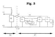
- FIG. 3 is shown the electronics converting the information captured by the clinometer in the preferred embodiment of the invention.
- the angle ⁇ is measured and converted into an oscillatory electrical signal 12, and the number of oscillations is counted and then interpreted by a microprocessor.
- An angle corresponds to an oscillation frequency.
- the supply of 3 Volts is carried out through conductive ball bearings 21 materializing the axis separating the machine and the support, occupying the left part of FIG. 3, of the measuring member whose electronics are shown diagrammatically in the right part of FIG. 3.
- An integrated regulator circuit 15 delivers a stabilized voltage of 3 Volts.
- the current consumption of the electronics of the device is approximately constant, which makes it possible to use the modulation of the current to communicate the angle ⁇ measured by the sensor 17.
- This sensor constituted by an electrolytic clinometer 17, is excited at 10 kHz with a load cycle of 50%. The excitement is achieved by switching alternately the sensor control electrodes 17 between 0 and 3 Volts.
- the 50% charge cycle is ensured by a component 16 representing a CMOS 4047 multivibrator circuit.
- the information captured is read by the central electrode of sensor 17. As, at a given angle, the voltage difference remains constant relative to to the control electrodes, which are permanently subjected to a polarity reversal, a sampling and holding circuit 18 is used to supply to a component 19, representing a voltage controlled oscillator and constituted by a CMOS 4046, the voltage read during the first half of the cycle.
- the voltage controlled oscillator 19 is adjusted to provide a frequency of the order of 1 kHz. Each change of polarity of the output produces a current pulse in the resistance-capacitance element 10, resulting in a voltage oscillation detectable via a resistance between the 5 Volts supply 11 and the oscillatory output 12. This output communicates with a processor used for optimization.
Landscapes
- Physics & Mathematics (AREA)
- General Physics & Mathematics (AREA)
- Engineering & Computer Science (AREA)
- Aviation & Aerospace Engineering (AREA)
- Aerodynamic Tests, Hydrodynamic Tests, Wind Tunnels, And Water Tanks (AREA)
- Testing Or Calibration Of Command Recording Devices (AREA)
Description
La présente invention concerne un dispositif de mesure d'angle, comme décrit dans le préambule de la revendication 1, notamment pour optimisation du rapport portance/traînée d'un engin mobile dans un fluide, et plus particulièrement d'un aéronef dans l'air, ainsi que pour la mesure des conditions d'écoulement de l'air autour d'un engin en soufflerie.The present invention relates to an angle measuring device, as described in the preamble of
Des dispositifs mesurant l'angle d'attaque sont connus et utilisés sur des avions: ils sont parfois disposés sur l'extrémité avant du nez de l'avion, pour ne pas être affectés par les perturbations générées par la pénétration de l'engin dans la masse fluide, ou plus souvent sur le côté extérieur du flanc de l'avion en transmettant l'information à un récepteur fixé à l'intérieur de l'avion. De tels capteurs sont décrits par exemple dans le brevet US 4,230,290.
La connaissance de l'angle d'attaque permet de mieux contrôler la portance de l'avion, et notamment d'éviter des décrochages dangereux.Devices measuring the angle of attack are known and used on aircraft: they are sometimes placed on the front end of the nose of the aircraft, so as not to be affected by the disturbances generated by the penetration of the craft into the fluid mass, or more often on the outside of the side of the plane by transmitting the information to a receiver fixed inside the plane. Such sensors are described for example in US patent 4,230,290.
Knowing the angle of attack makes it possible to better control the lift of the aircraft, and in particular to avoid dangerous stalls.
Cependant les dispositifs connus, même s'ils permettent de déterminer l'angle d'attaque avec une bonne précision, n'adressent pas le problème de fond de l'optimisation des conditions de déplacement d'un engin dans un fluide, et plus particulièrement des conditions de vol d'un aéronef dans l'air, qui consiste à mesurer et contrôler l'angle entre la direction du déplacement effectif de l'engin par rapport à la masse de fluide, qu'on appellera ci-après vecteur vitesse apparente conformément à l'usage, et la résultante de la portance, de la traînée et, dans le cas d'un engin motorisé, de la poussée, avec la plus grande précision possible. La direction de la résultante de ces forces s'exerçant sur l'engin, à l'exception de la force de gravitation terrestre, est celle que prendrait un fil à plomb ou pendule hypothétique suspendu au plafond d'un habitacle dans l'engin. On l'appellera dans la suite et dans les revendications la direction apparente de la pesanteur. Un observateur embarqué dans l'habitacle pourrait mesurer l'angle que ferait ce fil à plomb avec un axe lié à l'engin, mais il lui est difficile de mesurer l'angle qui est primordial pour l'optimisation, c'est-à-dire l'angle que ferait ce fil avec le vecteur vitesse, c'est-à-dire avec la direction du vent apparent dans le cas d'un aéronef.However, the known devices, even if they make it possible to determine the angle of attack with good precision, do not address the basic problem of optimizing the conditions of movement of a machine in a fluid, and more particularly flight conditions of an aircraft in the air, which consists in measuring and controlling the angle between the direction of the effective movement of the craft with respect to the mass of fluid, which will be referred to hereinafter as apparent speed vector according to use, and the result of lift, drag and, in the case of a motorized vehicle, thrust, with the greatest possible accuracy. The direction of the resultant of these forces exerted on the machine, with the exception of the earth's gravitational force, is that which would be taken by a hypothetical plumb line or pendulum suspended from the ceiling of a passenger compartment in the craft. It will be called hereinafter and in the claims the apparent direction of gravity. An observer on board the passenger compartment could measure the angle that this plumb line would make with an axis linked to the machine, but it is difficult for him to measure the angle which is essential for optimization, i.e. say the angle that this wire would make with the speed vector, that is to say with the apparent wind direction in the case of an aircraft.
Le problème à résoudre est donc de proposer un dispositif qui mesure directement, et avec une grande exactitude, cet angle entre la direction apparente de la pesanteur et le vecteur vitesse de l'engin par rapport au fluide.The problem to be solved is therefore to propose a device which directly measures, and with great accuracy, this angle between the apparent direction of gravity and the speed vector of the machine with respect to the fluid.
Dans le cas d'une soufflerie, la phase de tests d'une forme d'aéronef comporte la représentation des écoulements d'air dans un maximum de points du tunnel de soufflerie, avec en tout premier lieu la détermination de la direction du vent apparent, compte tenu des perturbations engendrées au voisinage de la forme d'aéronef. Là aussi, l'angle entre cette direction et la verticale au point de mesure est primordial.In the case of a wind tunnel, the test phase of an aircraft form includes the representation of air flows in a maximum number of points in the wind tunnel, with first of all the determination of the apparent wind direction , taking into account the disturbances generated in the vicinity of the aircraft form. Here too, the angle between this direction and the vertical at the measurement point is essential.
L'invention se propose de fournir un dispositif capable de mesurer de tels angles, par les moyens décrits dans la partie caractérisante de la revendication 1.The invention proposes to provide a device capable of measuring such angles, by the means described in the characterizing part of
Dans une réalisation avantageuse de l'invention, on utilise au moins un clinomètre consistant en un niveau à bulle de gaz ou d'air. Cette réalisation, compte tenu des niveaux à bulle d'air couramment disponibles, présente l'avantage de se contenter de dimensions très réduites, tout en offrant la précision nécessaire. Cette précision étant en général une fonction inverse de la plage de mesure du clinomètre considéré, il peut être souhaitable d'utiliser plus d'un clinomètre, pour mesurer aussi bien des angles fortement variables que des angles faiblement variables; pour ces derniers l'invention permet, après étalonnage, une précision de mesure allant jusqu'à la demi-seconde d'arc, c'est-à-dire le sept mille deux centième de degré. Cette précision est obtenue grâce à la présence d'un électrolyte liquide dans le niveau à bulle, ce qui fait que le moindre déplacement de la bulle entraîne une modification perceptible de la résistance électrique de l'électrolyte.In an advantageous embodiment of the invention, at least one clinometer is used consisting of a spirit level of gas or air. This achievement, given the commonly available air bubble levels, has the advantage of being content with very small dimensions, while providing the necessary precision. This precision is generally an inverse function of the measuring range of the clinometer considered, it may be desirable to use more than one clinometer, to measure sharp angles as well variables only slightly variable angles; for the latter the invention allows, after calibration, a measurement accuracy of up to half a second of arc, that is to say the seven thousand two hundredth of a degree. This precision is obtained thanks to the presence of a liquid electrolyte in the bubble level, which means that the slightest displacement of the bubble results in a perceptible change in the electrical resistance of the electrolyte.
Dans une autre réalisation de l'invention, on peut utiliser comme clinomètre un ou plusieurs accéléromètres dont la combinaison permet aussi de déduire la direction de l'accélération résultante à laquelle est soumis l'organe de mesure.In another embodiment of the invention, one or more accelerometers can be used as clinometer, the combination of which also makes it possible to deduce the direction of the resulting acceleration to which the measuring member is subjected.
Dans une réalisation avantageuse de l'invention, on donne au dispositif une forme aérodynamique lui permettant de trouver immédiatement et en toute circonstance la position qui d'une part annule le moment résultant autour de l'axe de rotation et où d'autre part le dispositif est aérodynamiquement stable. Ceci est obtenu, compte tenu de la contrainte selon laquelle son centre de gravité doit être porté par l'axe de rotation, par exemple par une paire d'ailettes.In an advantageous embodiment of the invention, the device is given an aerodynamic shape allowing it to find immediately and in all circumstances the position which on the one hand cancels the resulting moment around the axis of rotation and where on the other hand the device is aerodynamically stable. This is achieved, given the constraint that its center of gravity must be carried by the axis of rotation, for example by a pair of fins.
Dans une autre réalisation de l'invention, le support du dispositif est placé sur un engin mobile dans un fluide, en une position peu perturbée par les influences causées par le mouvement de la masse de fluide sur l'enveloppe de l'engin, ou en une position où ces influences sont connues. Cet endroit peut être notamment l'extrémité avant ou nez de l'engin, ou encore le bord d'attaque d'une aile dans le cas d'un aéronef, ou son extrémité.In another embodiment of the invention, the support of the device is placed on a mobile machine in a fluid, in a position little disturbed by the influences caused by the movement of the mass of fluid on the envelope of the machine, or in a position where these influences are known. This location may in particular be the front end or nose of the craft, or the leading edge of a wing in the case of an aircraft, or its end.
Dans une autre réalisation de l'invention, le support est muni d'un mécanisme qui en aligne, même approximativement, la direction sur celle du vecteur vitesse. De cette manière, on obtient les meilleures conditions de fonctionnement du dispositif, qui sont réalisées lorsque l'angle entre le support et le vecteur vitesse est faible; en effet ceci évite au maximum les influences qui sont causées par le support sur le fluide environnant le dispositif. De plus, le dispositif doit tourner librement , avec un frottement minimal, autour de son axe de rotation, ce qui est réalisé au mieux lorsque la direction du support est orthogonale à la direction du fluide, ainsi qu'à la direction apparente de la pesanteur. Ce mécanisme peut être par exemple, dans le cas d'un aéronef, un asservissement qui maintient le support dans une direction parallèle au vent apparent même en cas de virage, et plus généralement dans toutes les situations transitoires où le support n'est plus face au vent apparent, avec un temps de réponse amélioré. Cette amélioration du temps de réponse minimise le temps pendant lequel la mesure est perturbée.In another embodiment of the invention, the support is provided with a mechanism which aligns, even approximately, the direction with that of the speed vector. In this way, the best operating conditions of the device, which are produced when the angle between the support and the speed vector is small; in fact this avoids as much as possible the influences which are caused by the support on the fluid surrounding the device. In addition, the device must rotate freely, with minimal friction, around its axis of rotation, which is best achieved when the direction of the support is orthogonal to the direction of the fluid, as well as to the apparent direction of gravity. . This mechanism can be for example, in the case of an aircraft, a servo which maintains the support in a direction parallel to the apparent wind even in the event of a turn, and more generally in all transient situations where the support is no longer facing to the apparent wind, with an improved response time. This improvement in response time minimizes the time during which the measurement is disturbed.
D'autres réalisations avantageuses de l'invention ont comme but de minimiser les efforts de friction entre l'organe de mesure et le support: l'axe de rotation du dispositif est matérialisé par au moins un roulement, ou par un palier sans contact, par exemple au moyen d'un coussin de fluide ou d'un système d'asservissement magnétique. De telles réalisations peuvent être nécessaires pour réduire au minimum les frottements sur l'axe et obtenir ainsi la plus grande précision dans la mesure de l'angle.Other advantageous embodiments of the invention have the aim of minimizing the friction forces between the measuring member and the support: the axis of rotation of the device is embodied by at least one bearing, or by a non-contact bearing, for example by means of a fluid cushion or a magnetic servo system. Such embodiments may be necessary to minimize friction on the axis and thus obtain the greatest accuracy in the measurement of the angle.
Le dispositif fait appel à une source d'énergie, notamment électrique, pour son fonctionnement. Cette source d'énergie peut être incorporée au dispositif, comme par exemple une pile de dimensions adaptées, ou des capteurs solaires situés par exemple sur les ailettes. Elle peut aussi être embarquée à bord de l'engin, l'énergie pouvant alors être transmise au dispositif par différents moyens, notamment électromagnétiques comme par exemple une source de lumière véhiculée par fibres optiques, ou un rayonnement laser, ou un transformateur dont un enroulement primaire est alimenté par des moyens situés dans l'engin, et un enroulement secondaire est porté par le dispositif, ou électriques classiques avec au moins un conducteur suffisamment souple pour ne pas gêner la libre rotation de l'organe de mesure autour de son axe, ou, dans le cas où cet axe comprend au moins un roulement, au moyen du passage d'un courant électrique à travers ce roulement.The device uses a source of energy, in particular electric, for its operation. This energy source can be incorporated into the device, such as for example a battery of suitable dimensions, or solar collectors located for example on the fins. It can also be carried on board the vehicle, the energy then being able to be transmitted to the device by various means, in particular electromagnetic, such as for example a light source carried by optical fibers, or laser radiation, or a transformer including a winding. primary is powered by means located in the machine, and a secondary winding is carried by the device, or conventional electrics with at least one conductor flexible enough not to hinder the free rotation of the measuring member about its axis, or, in the case where this axis comprises at least one bearing, by means of the passage of an electric current through this bearing.
Les moyens de transmission de l'information captée par le dispositif peuvent faire appel à la source d'énergie évoquée précédemment. Dans le cas où cette information est transmise vers l'engin, ils peuvent faire appel au même moyen de transmission que cette source d'énergie.The means of transmitting the information received by the device can call on the energy source mentioned above. If this information is transmitted to the machine, they can use the same means of transmission as this energy source.
L'utilisation du dispositif concerne de façon préférée un aéronef, avec ou sans moteur, le fluide étant l'air. Il va de soi que les dimensions, la technologie et les matériaux utilisés pour la construction du dispositif seront adaptés aux conditions de vol: pour un planeur on choisira le bois ou une matière plastique, pour un avion de ligne ou une fusée sans pilote une structure métallique sera préférable. Ceci n'affecte en rien le principe de l'invention.The use of the device preferably relates to an aircraft, with or without an engine, the fluid being air. It goes without saying that the dimensions, technology and materials used for the construction of the device will be adapted to the flight conditions: for a glider we will choose wood or a plastic material, for an airliner or an unmanned rocket a structure metallic will be preferable. This in no way affects the principle of the invention.
Dans une autre réalisation de l'invention, notamment en soufflerie, l'engin est fixe et le fluide s'écoule autour de l'engin dans des conditions constantes qu'on cherche à mesurer. Dans cette utilisation, le support n'est pas forcément fixé sur l'engin mais peut être déplacé autant qu'on le désire dans le tunnel de la soufflerie, en mesurant à chaque position l'angle entre la direction du fluide et la verticale, qui coïncide ici avec la direction apparente de la pesanteur puisque le dispositif est fixe.In another embodiment of the invention, in particular in a wind tunnel, the machine is fixed and the fluid flows around the machine under constant conditions that one seeks to measure. In this use, the support is not necessarily fixed on the machine but can be moved as much as desired in the tunnel of the wind tunnel, by measuring at each position the angle between the direction of the fluid and the vertical, which coincides here with the apparent direction of gravity since the device is fixed.
Une autre utilisation du dispositif concerne une voiture de course automobile, soumise elle aussi à des forces d'accélération, de portance et de traînée. Le dispositif peut servir à optimiser la forme et la disposition des ailerons, becquets et spoilers, sur circuit ou en soufflerie, pour en améliorer les performances.Another use of the device concerns a motor racing car, which is also subject to acceleration, lift and drag forces. The device can be used to optimize the shape and arrangement of the ailerons, spoilers and spoilers, on the circuit or in a wind tunnel, to improve performance.
Une autre utilisation du dispositif est caractérisée en ce qu'un clinomètre solidaire de l'engin, situé dans son enveloppe et donc non soumis aux influences fluide-dynamiques, permet, par différence d'angle, de calculer l'angle entre le dispositif et l'engin indépendamment de l'accélération de l'engin. Ceci concerne par exemple la mesure précise de l'angle d'attaque de l'engin dans le fluide. En installant dans l'engin un capteur similaire mesurant de façon analogue et aussi précise l'angle entre l'axe de roulis de l'engin et la direction de la résultante des forces de portance, de traînée et éventuellement de poussée s'exerçant sur l'engin, l'invention permet aussi de calculer par différence l'angle d'attaque avec une très grande précision.Another use of the device is characterized in that a clinometer integral with the device, located in its envelope and therefore not subject to fluid-dynamic influences, makes it possible, by angle difference, to calculate the angle between the device and the craft regardless of the acceleration of the craft. This concerns for example the precise measurement of the angle of attack of the machine in the fluid. By installing in the machine a similar sensor measuring analogously and also precisely the angle between the roll axis of the machine and the direction of the result of the forces of lift, drag and possibly thrust exerted on the machine, the invention also makes it possible to calculate the angle of attack by difference with very high precision.
Une autre utilisation du dispositif concerne un engin sous-marin, le fluide étant un liquide et plus particulièrement de l'eau.Another use of the device relates to an underwater vehicle, the fluid being a liquid and more particularly water.
Dans d'autres utilisations du dispositif, un processeur, embarqué ou non à bord de l'engin, reçoit l'information transmise par les moyens de transmission et la convertit en un signal facile à interpréter pour l'optimisation du déplacement, c'est-à-dire du rapport entre les forces de portance, de traînée et éventuellement de poussée. Si cette tâche d'optimisation est confiée à un opérateur, par exemple un pilote, ce signal peut être affiché par des moyens visuels mais peut aussi par exemple être acoustique, ce qui lui permet d'effectuer simultanément d'autres tâches nécessitant un contact visuel.In other uses of the device, a processor, whether on board or not on board the machine, receives the information transmitted by the transmission means and converts it into an easy-to-interpret signal for optimizing the movement. ie the ratio between the forces of lift, drag and possibly thrust. If this optimization task is entrusted to an operator, for example a pilot, this signal can be displayed by visual means but can also, for example, be acoustic, which allows him to simultaneously perform other tasks requiring visual contact. .
D'autres dispositifs sont prévus pour maintenir des conditions de bon fonctionnement du clinomètre: si l'engin vole en haute atmosphère où prévalent des températures extrêmes, ou évolue à de grandes profondeurs où règnent de fortes pressions, la source d'énergie pourra également servir à le maintenir à sa température et sa pression normale de fonctionnement.Other devices are provided to maintain conditions of proper functioning of the clinometer: if the craft flies in a high atmosphere where extreme temperatures prevail, or operates at great depths where high pressures prevail, the energy source can also be used to maintain it at its normal operating temperature and pressure.
D'autres caractéristiques et avantages de l'invention apparaîtront dans la description détaillée ci-après d'une réalisation de l'invention, par référence aux dessins annexés dans lesquels:
- la figure 1 donne un aperçu de l'aéronef, de ses axes, et des vecteurs et forces intervenant dans son aérodynamique;
- la figure 2 représente le dispositif et son support;
- la figure 3 montre une réalisation du circuit électrique qui alimente le clinomètre et en capte les mesures.
- Figure 1 gives an overview of the aircraft, its axes, and the vectors and forces involved in its aerodynamics;
- Figure 2 shows the device and its support;
- FIG. 3 shows an embodiment of the electrical circuit which supplies the clinometer and captures its measurements.
La figure 1 représente un aéronef 1 muni d'un support 3 portant le dispositif 2. Le support 3 est approximativement parallèle à l'axe de roulis X de l'aéronef et a été placé sur le nez de l'aéronef, c'est-à-dire en un endroit protégé des influences causées dans la masse d'air par le mouvement de l'avion. Elle montre le vecteur vitesse V et la résultante de la portance L, de la traînée D et de la poussée T, avec l'angle β qui est à mesurer avec une grande précision.FIG. 1 represents an
La figure 2 montre le détail de la réalisation préférée du dispositif 2, monté mobile autour d'un axe 7 parallèle à l'axe de tangage Y de l'aéronef 1. L'axe 7 est matérialisé par un palier 4 à faible friction placé à l'extrémité du support 3. Le dispositif 2 a une forme qui le rend apte à s'orienter dans la direction du vecteur vitesse de l'engin. Il comporte à cet effet des ailettes 5. Le centre de gravité du dispositif 2 est situé par construction au centre du palier 4. Un clinomètre 6, par exemple un appareil commercialisé sous le nom de "Subminiature inclinometer" par Spectron Glass and Electronics Inc. (Uniondale, N.Y. 11553, U.S.A.) est incorporé dans le dispositif 2. Il mesure, dans le plan contenant l'axe de roulis X et l'axe de lacet Z, l'angle β que fait la projection sur ce plan du vecteur vitesse avec la projection sur ce même plan de la direction de la force obtenue comme résultante géométrique des forces s'exerçant sur l'aéronef, à l'exception de la force de gravitation. Ces forces comprennent la portance et la traînée dans le cas d'un planeur, et en plus la poussée dans le cas d'un avion propulsé. Comme les conditions de vol sont fonction de cet angle, on pourra à tout moment optimiser le vol. En particulier, dans le cas d'un avion propulsé, la consommation de carburant peut être réduite en agissant de manière connue sur divers paramètres tels que la position des volets, des ailerons, et du centre de gravité de l'avion par prélèvement du carburant dans un réservoir avant ou arrière. Les moyens (non représentés) utilisés pour transmettre, par exemple à un processeur, l'information utile à l'optimisation du vol sont situés dans l'enveloppe du dispositif 2 et sont alimentés par un ensemble de capteurs solaires 8 intégrés aux ailettes 5. La position de la bulle du clinomètre 6 est convertie sous forme électrique avec l'aide de cette source et transmise à l'engin par exemple à travers le palier 4 et le support 3.FIG. 2 shows the detail of the preferred embodiment of the
Dans la figure 3 est représentée l'électronique convertissant l'information captée par le clinomètre dans la réalisation préférée de l'invention. L'angle β est mesuré et converti en un signal électrique 12 oscillatoire, et le nombre d'oscillations est compté puis interprété par un microprocesseur. A une fréquence des oscillations correspond un angle.
L'alimentation de 3 Volts est réalisée à travers des roulements à billes conducteurs 21 matérialisant l'axe séparant l'engin et le support, occupant la partie gauche de la figure 3, de l'organe de mesure dont l'électronique est schématisée dans la partie droite de la figure 3. Un circuit intégré régulateur 15 délivre une tension stabilisée de 3 Volts. La consommation en courant de l'électronique du dispositif est approximativement constante, ce qui permet d'utiliser la modulation du courant pour communiquer l'angle β mesuré par le capteur 17. Ce capteur, constitué par un clinomètre électrolytique 17, est excité à 10 kHz avec un cycle de charge de 50%. L'excitation est réalisée en commutant de façon alternée les électrodes de commande du capteur 17 entre 0 et 3 Volts. Le cycle de charge de 50% est assuré par un composant 16 représentant un circuit multivibrateur CMOS 4047. L'information captée est lue par l'électrode centrale du capteur 17. Comme, à un angle donné, la différence de tension reste constante par rapport aux électrodes de commande, qui subissent en permanence une inversion de polarité, un circuit d'échantillonnage et de maintien 18 est utilisé pour fournir à un composant 19, représentant un oscillateur commandé par tension et constitué par un CMOS 4046, la tension lue pendant la première moitié du cycle. L'oscillateur commandé par tension 19 est réglé pour fournir une fréquence de l'ordre de 1 kHz. Chaque changement de polarité de la sortie produit une impulsion de courant dans l'élément résistance-capacité 10, résultant en une oscillation de tension détectable via une résistance entre l'alimentation 11 de 5 Volts et la sortie oscillatoire 12. Cette sortie communique avec un processeur servant à l'optimisation.In Figure 3 is shown the electronics converting the information captured by the clinometer in the preferred embodiment of the invention. The angle β is measured and converted into an oscillatory
The supply of 3 Volts is carried out through
Claims (10)
- Device permitting the measurement of the angle between the apparent direction of the plumb line (L+D+T) and the velocity vector of the device relative to the fluid in which it is immerged, characterised in that the device- is fixed on support (3), this support being equipped with an axis (7) which passes through the center of gravity of the device and which is maintained orthogonal to the plane defined by the apparent velocity of the fluid flowing around the device and the apparent plumb line,- is free to rotate around this axis and has one single position, around this axis, where the resultant moment from the fluid dynamic forces is zero and where it is fluid-dynamically stable,- contains a measurement system including at least one inclinometer (6) to measure this angle and means to transmit the information collected by the inclinometer(s).
- Device according to the claim 1, characterized in that the inclinometers (6) are liquid level meters.
- Device according to the claims 1 or 2, characterized in that it has an aerodynamic shape with a pair of fins stabilizing its position.
- Device according to one of the claims 1 to 3, characterized in that the support (3) is placed on a vehicle at a place with small perturbances or with known perturbances.
- Device according to one of the claims 1 to 4, characterized in that the support (3) has an adjustable direction using a servo mechanism to better maintain the orthogonality of the axis (7) and hence minimize perturbances related to transitional phases.
- Device according to one of the claims 1 to 5, characterized in that the device rotates around the axis (7) with little friction.
- Use of the device according to one of the claims 1 to 6, characterized in that the angle measured is the angle between the resultant of the lift, drag, and eventual thrust forces acting on a vehicle on which the device's support is attached, and the velocity vector of this support relative to the fluid.
- Use of the device according to one of the claims 1 to 6, characterized in that the fluid is moving in a wind tunnel, that the support is fixed, and hence permits the determination of the fluid flow at a specific point in the wind tunnel.
- Use of the device according to one of the claims 1 to 6, characterized in that an additional inclinometer attached to the vehicle permits by subtraction the calculation of the angle between the device and the vehicle, independently of the acceleration of the vehicle.
- Use of the device according to one of the claims 1 to 6, characterized in that a processor receives the information transmitted by the means of transmission and converts it into a signal easy to interpret, for example for the optimization of the lift/drag ratio of the vehicle.
Applications Claiming Priority (2)
| Application Number | Priority Date | Filing Date | Title |
|---|---|---|---|
| CH933/90 | 1990-03-21 | ||
| CH93390 | 1990-03-21 |
Publications (2)
| Publication Number | Publication Date |
|---|---|
| EP0447974A1 EP0447974A1 (en) | 1991-09-25 |
| EP0447974B1 true EP0447974B1 (en) | 1994-07-20 |
Family
ID=4198546
Family Applications (1)
| Application Number | Title | Priority Date | Filing Date |
|---|---|---|---|
| EP19910103998 Expired - Lifetime EP0447974B1 (en) | 1990-03-21 | 1991-03-15 | Angle measuring device and the use thereof |
Country Status (2)
| Country | Link |
|---|---|
| EP (1) | EP0447974B1 (en) |
| DE (1) | DE69102914T2 (en) |
Families Citing this family (1)
| Publication number | Priority date | Publication date | Assignee | Title |
|---|---|---|---|---|
| DE4429103A1 (en) * | 1994-08-17 | 1996-02-29 | Anemometerbau Gmbh Rostock | Wind strength and direction measuring method for e.g. energy prodn. early warning system |
Family Cites Families (3)
| Publication number | Priority date | Publication date | Assignee | Title |
|---|---|---|---|---|
| US2630987A (en) * | 1946-05-28 | 1953-03-10 | Kollsman Instr Corp | Automatic control for aircraft |
| US4230290A (en) * | 1978-05-01 | 1980-10-28 | Townsend Engineering Company | Airplane angle of attack and direction of flight indicator |
| US4541591A (en) * | 1983-04-01 | 1985-09-17 | The United States Of America As Represented By The Secretary Of The Navy | Guidance law to improve the accuracy of tactical missiles |
-
1991
- 1991-03-15 EP EP19910103998 patent/EP0447974B1/en not_active Expired - Lifetime
- 1991-03-15 DE DE1991602914 patent/DE69102914T2/en not_active Expired - Fee Related
Also Published As
| Publication number | Publication date |
|---|---|
| DE69102914T2 (en) | 1995-03-16 |
| DE69102914D1 (en) | 1994-08-25 |
| EP0447974A1 (en) | 1991-09-25 |
Similar Documents
| Publication | Publication Date | Title |
|---|---|---|
| EP0469991B1 (en) | Aircraft-mounted probe for measuring the aerodynamic parameters of the surrounding airflow | |
| EP3058431B1 (en) | Method and device for in-flight terrain identification for microdrone | |
| EP2193379B1 (en) | Method and device for obtaining the predictive vertical speed of a rotorcraft | |
| FR2886741A1 (en) | APPARATUS AND METHOD FOR DETERMINING THE ORIENTATION OF A MARINE FLUTE GUIDING DEVICE | |
| CA1280209C (en) | Method and system for determining the longitudinal position of the centre of gravity of an aircraft equipped with an adjustable horizontal tail unit and application to the monitoring of said centre of gravity in the neighbourhood of the aircraft aerodynamic centre | |
| EP2212196A1 (en) | Method and device for detecting and signalling the approach of a rotorcraft to a vortex domain | |
| EP3264214A1 (en) | Method for dynamic attitude conversion of a rotary-wing drone | |
| EP1547920B1 (en) | Process and device for reducing vibrations generated on a helicopter fuselage by means of a steerable horizontal stabilizer | |
| FR2958033A1 (en) | DEVICE FOR DISPLAYING THE ENERGY VARIATION OF AN AIRCRAFT, METHOD AND SYSTEM FOR DISPLAYING THE CORRESPONDING ENERGY VARIATION | |
| FR3112329A1 (en) | Vertical take-off flying device | |
| EP0406061A1 (en) | Apparatus attached to a moveable device to obtain signals representative of the speed of the device relative to a fluid, and measurement system incorporating such apparatus | |
| EP0680877B1 (en) | Transport aircraft with forward mounted stabilizer | |
| EP0447974A1 (en) | Angle measuring device and the use thereof | |
| WO2001008969A1 (en) | Remote-controlled mobile platform capable of operating in water or air environment | |
| Busch et al. | Cups, vanes, propellers, and laser anemometers | |
| FR2761643A1 (en) | Vehicle seat with variable mechanical damping | |
| EP0005662A1 (en) | Device for rapidly detecting a wind gradient | |
| EP0056747B1 (en) | Anemometer pole for measuring the relative speed between a fluid and a support, especially for an aircraft | |
| FR2558137A1 (en) | TAKE-OFF SPEED INDICATOR FOR AIRCRAFT | |
| JP7840585B1 (en) | flying object | |
| EP4105122B1 (en) | Method and device for assisting the piloting of a rotorcraft provided with at least one propeller | |
| WO2025104237A1 (en) | System for measuring the flying height of a hydrofoil boat | |
| WO2022148634A1 (en) | Device for estimating distance to a surface and length travelled | |
| FR3147375A1 (en) | Autonomous device with wind sensor | |
| FR3113893A1 (en) | Yaw stabilized stator rotary wing aircraft |
Legal Events
| Date | Code | Title | Description |
|---|---|---|---|
| PUAI | Public reference made under article 153(3) epc to a published international application that has entered the european phase |
Free format text: ORIGINAL CODE: 0009012 |
|
| AK | Designated contracting states |
Kind code of ref document: A1 Designated state(s): DE FR GB IT |
|
| 17P | Request for examination filed |
Effective date: 19920320 |
|
| 17Q | First examination report despatched |
Effective date: 19931007 |
|
| GRAA | (expected) grant |
Free format text: ORIGINAL CODE: 0009210 |
|
| AK | Designated contracting states |
Kind code of ref document: B1 Designated state(s): DE FR GB IT |
|
| REF | Corresponds to: |
Ref document number: 69102914 Country of ref document: DE Date of ref document: 19940825 |
|
| ITF | It: translation for a ep patent filed | ||
| GBT | Gb: translation of ep patent filed (gb section 77(6)(a)/1977) |
Effective date: 19941024 |
|
| PGFP | Annual fee paid to national office [announced via postgrant information from national office to epo] |
Ref country code: GB Payment date: 19950309 Year of fee payment: 5 |
|
| PGFP | Annual fee paid to national office [announced via postgrant information from national office to epo] |
Ref country code: FR Payment date: 19950317 Year of fee payment: 5 |
|
| PGFP | Annual fee paid to national office [announced via postgrant information from national office to epo] |
Ref country code: DE Payment date: 19950418 Year of fee payment: 5 |
|
| PLBE | No opposition filed within time limit |
Free format text: ORIGINAL CODE: 0009261 |
|
| STAA | Information on the status of an ep patent application or granted ep patent |
Free format text: STATUS: NO OPPOSITION FILED WITHIN TIME LIMIT |
|
| 26N | No opposition filed | ||
| PG25 | Lapsed in a contracting state [announced via postgrant information from national office to epo] |
Ref country code: GB Effective date: 19960315 |
|
| GBPC | Gb: european patent ceased through non-payment of renewal fee |
Effective date: 19960315 |
|
| PG25 | Lapsed in a contracting state [announced via postgrant information from national office to epo] |
Ref country code: FR Effective date: 19961129 |
|
| PG25 | Lapsed in a contracting state [announced via postgrant information from national office to epo] |
Ref country code: DE Effective date: 19961203 |
|
| REG | Reference to a national code |
Ref country code: FR Ref legal event code: ST |
|
| PG25 | Lapsed in a contracting state [announced via postgrant information from national office to epo] |
Ref country code: IT Free format text: LAPSE BECAUSE OF NON-PAYMENT OF DUE FEES;WARNING: LAPSES OF ITALIAN PATENTS WITH EFFECTIVE DATE BEFORE 2007 MAY HAVE OCCURRED AT ANY TIME BEFORE 2007. THE CORRECT EFFECTIVE DATE MAY BE DIFFERENT FROM THE ONE RECORDED. Effective date: 20050315 |