EP0447974B1 - Winkelmesseinrichtung und Verwendung derselben - Google Patents
Winkelmesseinrichtung und Verwendung derselben Download PDFInfo
- Publication number
- EP0447974B1 EP0447974B1 EP19910103998 EP91103998A EP0447974B1 EP 0447974 B1 EP0447974 B1 EP 0447974B1 EP 19910103998 EP19910103998 EP 19910103998 EP 91103998 A EP91103998 A EP 91103998A EP 0447974 B1 EP0447974 B1 EP 0447974B1
- Authority
- EP
- European Patent Office
- Prior art keywords
- support
- fluid
- angle
- axis
- vehicle
- Prior art date
- Legal status (The legal status is an assumption and is not a legal conclusion. Google has not performed a legal analysis and makes no representation as to the accuracy of the status listed.)
- Expired - Lifetime
Links
- 239000012530 fluid Substances 0.000 claims description 21
- 239000013598 vector Substances 0.000 claims description 11
- 230000005484 gravity Effects 0.000 claims description 8
- 238000005259 measurement Methods 0.000 claims description 8
- 230000001133 acceleration Effects 0.000 claims description 4
- 238000005457 optimization Methods 0.000 claims description 4
- 230000005540 biological transmission Effects 0.000 claims description 3
- 230000007246 mechanism Effects 0.000 claims description 3
- 239000007788 liquid Substances 0.000 claims description 2
- 230000000087 stabilizing effect Effects 0.000 claims 1
- 230000010355 oscillation Effects 0.000 description 3
- 230000008901 benefit Effects 0.000 description 2
- 230000008859 change Effects 0.000 description 2
- 238000010276 construction Methods 0.000 description 2
- 239000000446 fuel Substances 0.000 description 2
- 239000000463 material Substances 0.000 description 2
- 230000003534 oscillatory effect Effects 0.000 description 2
- 230000004044 response Effects 0.000 description 2
- 230000000007 visual effect Effects 0.000 description 2
- 238000004804 winding Methods 0.000 description 2
- 239000004020 conductor Substances 0.000 description 1
- 238000006073 displacement reaction Methods 0.000 description 1
- 239000003792 electrolyte Substances 0.000 description 1
- 238000005516 engineering process Methods 0.000 description 1
- 239000011521 glass Substances 0.000 description 1
- 230000006872 improvement Effects 0.000 description 1
- 239000011244 liquid electrolyte Substances 0.000 description 1
- 239000013307 optical fiber Substances 0.000 description 1
- 230000035515 penetration Effects 0.000 description 1
- 230000005855 radiation Effects 0.000 description 1
- 238000005070 sampling Methods 0.000 description 1
- 230000001052 transient effect Effects 0.000 description 1
- XLYOFNOQVPJJNP-UHFFFAOYSA-N water Substances O XLYOFNOQVPJJNP-UHFFFAOYSA-N 0.000 description 1
- 239000002023 wood Substances 0.000 description 1
Images

Classifications
-
- G—PHYSICS
- G01—MEASURING; TESTING
- G01P—MEASURING LINEAR OR ANGULAR SPEED, ACCELERATION, DECELERATION, OR SHOCK; INDICATING PRESENCE, ABSENCE, OR DIRECTION, OF MOVEMENT
- G01P13/00—Indicating or recording presence, absence, or direction, of movement
- G01P13/02—Indicating direction only, e.g. by weather vane
-
- B—PERFORMING OPERATIONS; TRANSPORTING
- B64—AIRCRAFT; AVIATION; COSMONAUTICS
- B64D—EQUIPMENT FOR FITTING IN OR TO AIRCRAFT; FLIGHT SUITS; PARACHUTES; ARRANGEMENT OR MOUNTING OF POWER PLANTS OR PROPULSION TRANSMISSIONS IN AIRCRAFT
- B64D43/00—Arrangements or adaptations of instruments
- B64D43/02—Arrangements or adaptations of instruments for indicating aircraft speed or stalling conditions
Definitions
- the present invention relates to an angle measuring device, as described in the preamble of claim 1, in particular for optimizing the lift / drag ratio of a mobile machine in a fluid, and more particularly of an aircraft in air , as well as for measuring the air flow conditions around a machine in a wind tunnel.
- Devices measuring the angle of attack are known and used on aircraft: they are sometimes placed on the front end of the nose of the aircraft, so as not to be affected by the disturbances generated by the penetration of the craft into the fluid mass, or more often on the outside of the side of the plane by transmitting the information to a receiver fixed inside the plane.
- sensors are described for example in US patent 4,230,290. Knowing the angle of attack makes it possible to better control the lift of the aircraft, and in particular to avoid dangerous stalls.
- the known devices do not address the basic problem of optimizing the conditions of movement of a machine in a fluid, and more particularly flight conditions of an aircraft in the air, which consists in measuring and controlling the angle between the direction of the effective movement of the craft with respect to the mass of fluid, which will be referred to hereinafter as apparent speed vector according to use, and the result of lift, drag and, in the case of a motorized vehicle, thrust, with the greatest possible accuracy.
- the direction of the resultant of these forces exerted on the machine is that which would be taken by a hypothetical plumb line or pendulum suspended from the ceiling of a passenger compartment in the craft.
- the problem to be solved is therefore to propose a device which directly measures, and with great accuracy, this angle between the apparent direction of gravity and the speed vector of the machine with respect to the fluid.
- the test phase of an aircraft form includes the representation of air flows in a maximum number of points in the wind tunnel, with first of all the determination of the apparent wind direction , taking into account the disturbances generated in the vicinity of the aircraft form.
- the angle between this direction and the vertical at the measurement point is essential.
- the invention proposes to provide a device capable of measuring such angles, by the means described in the characterizing part of claim 1.
- At least one clinometer is used consisting of a spirit level of gas or air.
- This achievement given the commonly available air bubble levels, has the advantage of being content with very small dimensions, while providing the necessary precision.
- This precision is generally an inverse function of the measuring range of the clinometer considered, it may be desirable to use more than one clinometer, to measure sharp angles as well variables only slightly variable angles; for the latter the invention allows, after calibration, a measurement accuracy of up to half a second of arc, that is to say the seven thousand two hundredth of a degree.
- This precision is obtained thanks to the presence of a liquid electrolyte in the bubble level, which means that the slightest displacement of the bubble results in a perceptible change in the electrical resistance of the electrolyte.
- one or more accelerometers can be used as clinometer, the combination of which also makes it possible to deduce the direction of the resulting acceleration to which the measuring member is subjected.
- the device is given an aerodynamic shape allowing it to find immediately and in all circumstances the position which on the one hand cancels the resulting moment around the axis of rotation and where on the other hand the device is aerodynamically stable. This is achieved, given the constraint that its center of gravity must be carried by the axis of rotation, for example by a pair of fins.
- the support of the device is placed on a mobile machine in a fluid, in a position little disturbed by the influences caused by the movement of the mass of fluid on the envelope of the machine, or in a position where these influences are known.
- This location may in particular be the front end or nose of the craft, or the leading edge of a wing in the case of an aircraft, or its end.
- the support is provided with a mechanism which aligns, even approximately, the direction with that of the speed vector.
- the best operating conditions of the device which are produced when the angle between the support and the speed vector is small; in fact this avoids as much as possible the influences which are caused by the support on the fluid surrounding the device.
- the device must rotate freely, with minimal friction, around its axis of rotation, which is best achieved when the direction of the support is orthogonal to the direction of the fluid, as well as to the apparent direction of gravity. .
- This mechanism can be for example, in the case of an aircraft, a servo which maintains the support in a direction parallel to the apparent wind even in the event of a turn, and more generally in all transient situations where the support is no longer facing to the apparent wind, with an improved response time. This improvement in response time minimizes the time during which the measurement is disturbed.
- the axis of rotation of the device is embodied by at least one bearing, or by a non-contact bearing, for example by means of a fluid cushion or a magnetic servo system.
- Such embodiments may be necessary to minimize friction on the axis and thus obtain the greatest accuracy in the measurement of the angle.
- the device uses a source of energy, in particular electric, for its operation.
- This energy source can be incorporated into the device, such as for example a battery of suitable dimensions, or solar collectors located for example on the fins. It can also be carried on board the vehicle, the energy then being able to be transmitted to the device by various means, in particular electromagnetic, such as for example a light source carried by optical fibers, or laser radiation, or a transformer including a winding.
- electromagnetic such as for example a light source carried by optical fibers, or laser radiation, or a transformer including a winding.
- primary is powered by means located in the machine, and a secondary winding is carried by the device, or conventional electrics with at least one conductor flexible enough not to hinder the free rotation of the measuring member about its axis, or, in the case where this axis comprises at least one bearing, by means of the passage of an electric current through this bearing.
- the means of transmitting the information received by the device can call on the energy source mentioned above. If this information is transmitted to the machine, they can use the same means of transmission as this energy source.
- the use of the device preferably relates to an aircraft, with or without an engine, the fluid being air. It goes without saying that the dimensions, technology and materials used for the construction of the device will be adapted to the flight conditions: for a glider we will choose wood or a plastic material, for an airliner or an unmanned rocket a structure metallic will be preferable. This in no way affects the principle of the invention.
- the machine in particular in a wind tunnel, the machine is fixed and the fluid flows around the machine under constant conditions that one seeks to measure.
- the support is not necessarily fixed on the machine but can be moved as much as desired in the tunnel of the wind tunnel, by measuring at each position the angle between the direction of the fluid and the vertical, which coincides here with the apparent direction of gravity since the device is fixed.
- the device can be used to optimize the shape and arrangement of the ailerons, spoilers and spoilers, on the circuit or in a wind tunnel, to improve performance.
- Another use of the device is characterized in that a clinometer integral with the device, located in its envelope and therefore not subject to fluid-dynamic influences, makes it possible, by angle difference, to calculate the angle between the device and the craft regardless of the acceleration of the craft.
- the invention By installing in the machine a similar sensor measuring analogously and also precisely the angle between the roll axis of the machine and the direction of the result of the forces of lift, drag and possibly thrust exerted on the machine, the invention also makes it possible to calculate the angle of attack by difference with very high precision.
- Another use of the device relates to an underwater vehicle, the fluid being a liquid and more particularly water.
- a processor receives the information transmitted by the transmission means and converts it into an easy-to-interpret signal for optimizing the movement. ie the ratio between the forces of lift, drag and possibly thrust. If this optimization task is entrusted to an operator, for example a pilot, this signal can be displayed by visual means but can also, for example, be acoustic, which allows him to simultaneously perform other tasks requiring visual contact. .
- FIG. 1 represents an aircraft 1 provided with a support 3 carrying the device 2.
- the support 3 is approximately parallel to the roll axis X of the aircraft and has been placed on the nose of the aircraft, that is that is to say in a place protected from the influences caused in the air mass by the movement of the plane. It shows the speed vector V and the result of the lift L, the drag D and the thrust T, with the angle ⁇ which is to be measured with great precision.
- FIG. 2 shows the detail of the preferred embodiment of the device 2, mounted mobile around an axis 7 parallel to the pitch axis Y of the aircraft 1.
- the axis 7 is materialized by a bearing 4 with low friction placed at the end of the support 3.
- the device 2 has a shape which makes it capable of orienting itself in the direction of the speed vector of the machine. For this purpose, it includes fins 5.
- the center of gravity of the device 2 is located by construction in the center of the bearing 4.
- a clinometer 6, for example an apparatus marketed under the name of "Subminiature inclinometer” by Spectron Glass and Electronics Inc. (Uniondale, NY 11553, USA) is incorporated in device 2.
- the means (not shown) used to transmit, for example to a processor, the information useful for optimizing the flight are located in the envelope of the device 2 and are supplied by a set of solar collectors 8 integrated into the fins 5.
- the position of the clinometer bubble 6 is converted into electrical form with the help of this source and transmitted to the vehicle for example through the bearing 4 and the support 3.
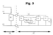
- FIG. 3 is shown the electronics converting the information captured by the clinometer in the preferred embodiment of the invention.
- the angle ⁇ is measured and converted into an oscillatory electrical signal 12, and the number of oscillations is counted and then interpreted by a microprocessor.
- An angle corresponds to an oscillation frequency.
- the supply of 3 Volts is carried out through conductive ball bearings 21 materializing the axis separating the machine and the support, occupying the left part of FIG. 3, of the measuring member whose electronics are shown diagrammatically in the right part of FIG. 3.
- An integrated regulator circuit 15 delivers a stabilized voltage of 3 Volts.
- the current consumption of the electronics of the device is approximately constant, which makes it possible to use the modulation of the current to communicate the angle ⁇ measured by the sensor 17.
- This sensor constituted by an electrolytic clinometer 17, is excited at 10 kHz with a load cycle of 50%. The excitement is achieved by switching alternately the sensor control electrodes 17 between 0 and 3 Volts.
- the 50% charge cycle is ensured by a component 16 representing a CMOS 4047 multivibrator circuit.
- the information captured is read by the central electrode of sensor 17. As, at a given angle, the voltage difference remains constant relative to to the control electrodes, which are permanently subjected to a polarity reversal, a sampling and holding circuit 18 is used to supply to a component 19, representing a voltage controlled oscillator and constituted by a CMOS 4046, the voltage read during the first half of the cycle.
- the voltage controlled oscillator 19 is adjusted to provide a frequency of the order of 1 kHz. Each change of polarity of the output produces a current pulse in the resistance-capacitance element 10, resulting in a voltage oscillation detectable via a resistance between the 5 Volts supply 11 and the oscillatory output 12. This output communicates with a processor used for optimization.
Landscapes
- Physics & Mathematics (AREA)
- General Physics & Mathematics (AREA)
- Engineering & Computer Science (AREA)
- Aviation & Aerospace Engineering (AREA)
- Aerodynamic Tests, Hydrodynamic Tests, Wind Tunnels, And Water Tanks (AREA)
- Testing Or Calibration Of Command Recording Devices (AREA)
Claims (10)
- Gerät zur Bestimmung des Winkels zwischen der Scheinlotlinie (L+D+T) und dem Geschwindigkeitsvektor von dem Gerät relativ zur umgebenden Flüssigkeit, dadurch gekennzeichnet, dass das Gerät- auf einen Halter (3) befestigt ist, welcher mit einer Rotationsachse (7) versehen ist,
dass diese Rotationsachse durch das Massenzentrum von dem Gerät geht,
dass diese Rotationsachse immer orthogonal bezüglich einen Plan, der vom Umgebungsflüssigkeitsrelativgeschwindigkeitsvektor und von der Scheinlotlinie definiert ist,
dass das Gerät weiter- sich frei um die Rotationsachse drehen kann und nur eine Position um diese Rotationsachse hat, wo das Gerät aerodynamisch stabil ist, das heisst, wo der Resultantmoment von den aerodynamischen Kräften Null ist,- ein Messystem hat, das mindestens ein Inklinometer (6) einschliesst, um diesen Winkel zu messen, und Mittel zur Ueberführung von Inklinometerdaten. - Gerät nach Anspruch 1, dadurch gekennzeichnet, dass die Inklinometer (6) Flüssigkeitsmeter sind.
- Gerät nach einem der Ansprüche 1 und 2, dadurch gekennzeichnet, dass das Gerät eine aerodynamische Form hat und mit Stabilisierungsflächen ausgerüstet ist.
- Gerät nach einem der Ansprüche 1 bis 3, dadurch gekennzeichnet, dass der Halter (3) auf ein Flugzeug montiert ist, auf eine Stelle wo Störungen klein oder bekannt sind.
- Gerät nach einem der Ansprüche 1 bis 4, dadurch gekennzeichnet, dass der Halter (3) einen regulierbaren Befestigungsmechanismus hat, um besser die Orthogonalität von der Rotationsachse (7) beizubehalten, und deshalb vorübergehende Störungen reduziert.
- Gerät nach einem der Ansprüche 1 und 5, dadurch gekennzeichnet, dass die Rotationsachse (7) ein niedriger Rotationswiderstand hat.
- Anwendung von dem Gerät nach einem der Ansprüche 1 bis 6, dadurch gekennzeichnet, dass der gemessene Winkel der Winkel zwischen a) der Resultante von Auftriebskräften, Widerstandskräften und eventuell Triebkräften auf ein Flugzeug, auf welchem der Halter montiert ist, und b) dem Relativgeschwindigkeitsvektor des Halters in die Umgebungsflüssigkeit ist.
- Anwendung von dem Gerät nach einem der Ansprüche 1 bis 6, dadurch gekennzeichnet, dass die Flüssigkeit ein Gas, das durch einen Windkanal gebläst wird ist, dass der Halter (3) stationär ist und deshalb erlaubt, die Gasstromrichtung an einer gegebener Stelle im Kanal zu messen.
- Anwendung von dem Gerät nach einem der Ansprüche 1 bis 6, dadurch gekennzeichnet, dass ein zusätzlicher Inklinometer auf das Flugzeug montiert ist, so dass durch Subtraktion der Winkel zwischen dem Gerät und dem Flugzeug berechnet werden kann, unabhängig von der aktuellen Beschleunigung.
- Anwendung von dem Gerät nach einem der Ansprüche 1 bis 6, dadurch gekennzeichnet, dass ein Prozessor die von den Mitteln überführte Daten empfängt via ein Datenübertragungskanal, und davon ein einfach zu verstehen Signal bearbeitet, zum Beispiel zur Optimierung von dem Auftrieb/Widerstandsverhältnis der Flugzeug.
Applications Claiming Priority (2)
| Application Number | Priority Date | Filing Date | Title |
|---|---|---|---|
| CH933/90 | 1990-03-21 | ||
| CH93390 | 1990-03-21 |
Publications (2)
| Publication Number | Publication Date |
|---|---|
| EP0447974A1 EP0447974A1 (de) | 1991-09-25 |
| EP0447974B1 true EP0447974B1 (de) | 1994-07-20 |
Family
ID=4198546
Family Applications (1)
| Application Number | Title | Priority Date | Filing Date |
|---|---|---|---|
| EP19910103998 Expired - Lifetime EP0447974B1 (de) | 1990-03-21 | 1991-03-15 | Winkelmesseinrichtung und Verwendung derselben |
Country Status (2)
| Country | Link |
|---|---|
| EP (1) | EP0447974B1 (de) |
| DE (1) | DE69102914T2 (de) |
Families Citing this family (1)
| Publication number | Priority date | Publication date | Assignee | Title |
|---|---|---|---|---|
| DE4429103A1 (de) * | 1994-08-17 | 1996-02-29 | Anemometerbau Gmbh Rostock | Verfahren und Einrichtung zur Windmessung |
Family Cites Families (3)
| Publication number | Priority date | Publication date | Assignee | Title |
|---|---|---|---|---|
| US2630987A (en) * | 1946-05-28 | 1953-03-10 | Kollsman Instr Corp | Automatic control for aircraft |
| US4230290A (en) * | 1978-05-01 | 1980-10-28 | Townsend Engineering Company | Airplane angle of attack and direction of flight indicator |
| US4541591A (en) * | 1983-04-01 | 1985-09-17 | The United States Of America As Represented By The Secretary Of The Navy | Guidance law to improve the accuracy of tactical missiles |
-
1991
- 1991-03-15 DE DE1991602914 patent/DE69102914T2/de not_active Expired - Fee Related
- 1991-03-15 EP EP19910103998 patent/EP0447974B1/de not_active Expired - Lifetime
Also Published As
| Publication number | Publication date |
|---|---|
| EP0447974A1 (de) | 1991-09-25 |
| DE69102914T2 (de) | 1995-03-16 |
| DE69102914D1 (de) | 1994-08-25 |
Similar Documents
| Publication | Publication Date | Title |
|---|---|---|
| EP0469991B1 (de) | Fühler für Luftfahrzeuge zum Messen der aerodynamischen Parameter der umgebenden Strömung | |
| EP3058431B1 (de) | Verfahren und vorrichtung zur geländeidentifikation während des fluges einer mikrodrohne | |
| FR2990276A1 (fr) | Appareil et procede de determination de l'orientation d'un dispositif de guidage de flute marine | |
| CA1280209C (fr) | Procede et systeme pour la determination de la position longitudinale du centre de gravite d'un aeronef pourvu d'un empennage horizontal reglable et application a la surveillance dudit centre de gravite au voisinage du foyer de l'aeronef | |
| EP3264214A1 (de) | Verfahren zur dynamischen fluglage-konvertierung eines drehflügeldrohne | |
| FR2958033A1 (fr) | Dispositif d'affichage de la variation d'energie d'un aeronef, procede et systeme d'affichage de la variation d'energie correspondants | |
| EP1547920B1 (de) | Verfahren und Vorrichtung zur Verminderung der Vibrationen eines Hubschrauberrumpfes, mittels eines steuerbaren Höhenleitwerks | |
| EP2193379A2 (de) | Verfahren und vorrichtung zum erreichen der prognostischen steig- und sinkgeschwindigkeit bei einem drehflügler | |
| FR3112329A1 (fr) | Dispositif volant à décollage vertical | |
| EP0406061A1 (de) | Mit einer bewegbaren Vorrichtung verbundener Apparat zur Erfassung von Signalen, die der Geschwindigkeit dieser Vorrichtung in einem Fluidum entsprechen sowie Messgerät mit einer solchen Vorrichtung | |
| EP0447974B1 (de) | Winkelmesseinrichtung und Verwendung derselben | |
| EP0680877B1 (de) | Transportflugzeug mit Vorderhöhenruder | |
| WO2001008969A1 (fr) | Plate-forme mobile telecommandee apte a evoluer dans un milieu tel que l'eau ou l'air | |
| EP2333564A1 (de) | Servogesteuertes bistatisches Staurohr | |
| Busch et al. | Cups, vanes, propellers, and laser anemometers | |
| EP0005662A1 (de) | Einrichtung zur schnellen Feststellung des Windgefälles | |
| FR2558137A1 (fr) | Indicateur de vitesse de decollage pour aeronefs | |
| JP7840585B1 (ja) | 飛行体 | |
| EP4105122B1 (de) | Verfahren und vorrichtung zur steuerungsunterstützung eines drehflüglers mit mindestens einem propeller | |
| WO2025104237A1 (fr) | Système de mesure de la hauteur de vol d'un bateau à foil | |
| WO2022148634A1 (fr) | Dispositif d'estimation de distance a une surface et de longueur parcourue | |
| WO2024201374A1 (fr) | Engin autonome avec capteur de vent | |
| JP2026070588A (ja) | 飛行体 | |
| FR3113893A1 (fr) | Aéronef à voilure tournante à stator stabilisé en lacet | |
| FR2514512A1 (fr) | Dispositif anemometrique embarquable a detection |
Legal Events
| Date | Code | Title | Description |
|---|---|---|---|
| PUAI | Public reference made under article 153(3) epc to a published international application that has entered the european phase |
Free format text: ORIGINAL CODE: 0009012 |
|
| AK | Designated contracting states |
Kind code of ref document: A1 Designated state(s): DE FR GB IT |
|
| 17P | Request for examination filed |
Effective date: 19920320 |
|
| 17Q | First examination report despatched |
Effective date: 19931007 |
|
| GRAA | (expected) grant |
Free format text: ORIGINAL CODE: 0009210 |
|
| AK | Designated contracting states |
Kind code of ref document: B1 Designated state(s): DE FR GB IT |
|
| REF | Corresponds to: |
Ref document number: 69102914 Country of ref document: DE Date of ref document: 19940825 |
|
| ITF | It: translation for a ep patent filed | ||
| GBT | Gb: translation of ep patent filed (gb section 77(6)(a)/1977) |
Effective date: 19941024 |
|
| PGFP | Annual fee paid to national office [announced via postgrant information from national office to epo] |
Ref country code: GB Payment date: 19950309 Year of fee payment: 5 |
|
| PGFP | Annual fee paid to national office [announced via postgrant information from national office to epo] |
Ref country code: FR Payment date: 19950317 Year of fee payment: 5 |
|
| PGFP | Annual fee paid to national office [announced via postgrant information from national office to epo] |
Ref country code: DE Payment date: 19950418 Year of fee payment: 5 |
|
| PLBE | No opposition filed within time limit |
Free format text: ORIGINAL CODE: 0009261 |
|
| STAA | Information on the status of an ep patent application or granted ep patent |
Free format text: STATUS: NO OPPOSITION FILED WITHIN TIME LIMIT |
|
| 26N | No opposition filed | ||
| PG25 | Lapsed in a contracting state [announced via postgrant information from national office to epo] |
Ref country code: GB Effective date: 19960315 |
|
| GBPC | Gb: european patent ceased through non-payment of renewal fee |
Effective date: 19960315 |
|
| PG25 | Lapsed in a contracting state [announced via postgrant information from national office to epo] |
Ref country code: FR Effective date: 19961129 |
|
| PG25 | Lapsed in a contracting state [announced via postgrant information from national office to epo] |
Ref country code: DE Effective date: 19961203 |
|
| REG | Reference to a national code |
Ref country code: FR Ref legal event code: ST |
|
| PG25 | Lapsed in a contracting state [announced via postgrant information from national office to epo] |
Ref country code: IT Free format text: LAPSE BECAUSE OF NON-PAYMENT OF DUE FEES;WARNING: LAPSES OF ITALIAN PATENTS WITH EFFECTIVE DATE BEFORE 2007 MAY HAVE OCCURRED AT ANY TIME BEFORE 2007. THE CORRECT EFFECTIVE DATE MAY BE DIFFERENT FROM THE ONE RECORDED. Effective date: 20050315 |