EP0448071B1 - Système de commande pour radio-récepteur - Google Patents
Système de commande pour radio-récepteur Download PDFInfo
- Publication number
- EP0448071B1 EP0448071B1 EP91104325A EP91104325A EP0448071B1 EP 0448071 B1 EP0448071 B1 EP 0448071B1 EP 91104325 A EP91104325 A EP 91104325A EP 91104325 A EP91104325 A EP 91104325A EP 0448071 B1 EP0448071 B1 EP 0448071B1
- Authority
- EP
- European Patent Office
- Prior art keywords
- analogue
- digital
- converter
- control unit
- control
- Prior art date
- Legal status (The legal status is an assumption and is not a legal conclusion. Google has not performed a legal analysis and makes no representation as to the accuracy of the status listed.)
- Expired - Lifetime
Links
Images




Classifications
-
- H—ELECTRICITY
- H03—ELECTRONIC CIRCUITRY
- H03G—CONTROL OF AMPLIFICATION
- H03G3/00—Gain control in amplifiers or frequency changers
- H03G3/20—Automatic control
- H03G3/30—Automatic control in amplifiers having semiconductor devices
- H03G3/3052—Automatic control in amplifiers having semiconductor devices in bandpass amplifiers (H.F. or I.F.) or in frequency-changers used in a (super)heterodyne receiver
-
- H—ELECTRICITY
- H03—ELECTRONIC CIRCUITRY
- H03G—CONTROL OF AMPLIFICATION
- H03G3/00—Gain control in amplifiers or frequency changers
- H03G3/001—Digital control of analog signals
Definitions
- the invention relates to a digital control device for electrical signals, in particular for the intermediate frequency (IF) signal in a radio receiver according to the preamble of claim 1, and to a circuit having a plurality of such control devices connected in series.
- IF intermediate frequency
- a combination of input attenuation and control of the level in the IF amplifier is therefore usually chosen, with the larger control scope being applied to the IF amplifier of 100-120 dB, for example, and a regulation of 10-40 dB is not required for the input attenuator.
- This control is generally carried out as a backward control, the IF output level serving as the control criterion (cf. Meinke / Gundlach "Taschenbuch der Hochfrequenztechnik" (1986), Q 34 (D2)).
- the IF voltage is rectified and separated from the IF and modulation frequency by a filter element.
- This filter element forms the control time constant, which determines the control speed.
- the DC voltage obtained in this way is amplified in a control amplifier and fed as a control voltage to the IF amplifier or the input attenuator as a control voltage. With a large range of rules, several amplifier stages are connected in series.
- a digital control is also known (cf. DE-A-21 61 657 and DE-A-21 64 846), in which the control DC voltage is compared with two threshold voltages in a window comparator. Control signals are generated for an up / down-counting binary counter, the counter reading of which reaches a digital / analog (D / A) converter, which uses it to obtain an analog voltage for regulating the IF amplifier or the input attenuator.
- This digital control device represents a combination of analog gain change with digital control, usually using controllable semiconductors such as diodes, transistors and operational amplifiers, which due to their thermal sensitivity and tolerances in linearity for multi-channel applications in which high synchronism is required lead to a considerable selection effort.
- D2 (Q 36) specifies a switched IF amplifier, which consists of a chain of similar amplifier stages, the gain of which can be switched in a staggered binary manner.
- This digital IF control also receives the control signals via a binary counter.
- This control loop acts as Integrating controller, since the control loop only comes to rest when the rectified IF output voltage has reached its setpoint. The control speed is determined by the clock frequency of the binary counter.
- the object of the invention is to regulate an electrical signal very quickly over a large dynamic range with an essentially constant amplitude.
- a control circuit according to the preamble of claim 1 is known from EP-A-0 272 161.
- the invention is based on the basic idea that a digital quantity is obtained from the input signal and then inverted, and thus the input signal serving as a reference signal is regulated in such a way that the output signal remains essentially constant even when the size of the input signal changes significantly .
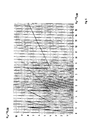
- the voltage U e to be regulated is applied both to a multiplying D / A converter 1 as a reference signal U REF and to an A / D converter 2 which converts the voltage into a digital value.
- This value is switched to the control inputs of the D / A converter 1 in a coding circuit 3 and possibly via a buffer 4.
- the D / A converter multiplies the input voltage by the digital value and supplies an output voltage U a (cf.
- the A / D converter 2 converts the input voltage U e to be controlled into a digital value: Z.
- a / D U e / U LSB , where U LSB is the smallest voltage that can be resolved, and Z A / D covers the range 0 to (2 n -1) with n as the number of bits.
- This digital value Z A / D is recoded into Z ' A / D and applied to the control inputs of the D / A converter (possibly via a buffer). If the reference voltage U REF is replaced by U e , an output voltage is obtained at the output of the D / A converter according to the following function:
- the voltage generated in this way and dependent on the coding of the D / A converter data can serve as input voltage for a similar circuit device.
- An output voltage is obtained in the same way.
- Such circuits can be cascaded as desired.
- an AC voltage U e is applied to the reference input of a D / A converter 1 on the one hand and to the A / D converter 2 via a rectifier 5 and an amplifier 6 on the other hand.
- the A / D converter is implemented, for example, according to the parallel method.
- the reference outputs of the comparators K1 to K4 are staggered such that the comparator states change each time the input voltage is doubled.
- the comparator outputs serve as digital control information for an 8-bit D / A converter.
- the coding of this control information consists in that the comparator outputs are only swapped to the 4 higher-order control inputs of the D / A converter in the order of their values (without conversion to dual numbers).
- the 4 lowest control inputs of the D / A converter are firmly at the highest potential.
- the data of the A / D converter 2 are recoded in dual numbers and connected to a D / A converter with the order of their values reversed.
- the A / D converter supplies the digital data Z.
- a / D U e U LSB which can assume the values from 0 to 15 in the case of a 4-bit converter.
- the D / A converter 1 whose four lowest control inputs are again firmly at the highest potential, is controlled with this digital value Z ' A / D and supplies the output voltage:
- U a U LSB - 15 16 ⁇ U e U LSB + 1 16 U e U LSB 2nd
- control device according to the invention in a multi-channel receiver, such as DF receiver using the Watson-Watt method, has proven to be insensitive to it Overdrive effects, which can result in significant bearing errors, are particularly advantageous.
- all the A / D converter outputs are connected in parallel in stages, so that the channel with the strongest signal amplitude automatically determines the control state and thus the simultaneous control of all stages is ensured.
- the cascaded control stages 10 and the distributed selection means 11 it is advisable to switch the A / D converter data to a microprocessor controller 9 via a parallel port 8.
- the microprocessor receives precise status information about the control state of the receiver and can control the control stages in time in a signal-optimized manner if necessary (different holding time constants by time control signal 12).
- the reception field strength can be precisely determined and evaluated.
Landscapes
- Analogue/Digital Conversion (AREA)
- Control Of Amplification And Gain Control (AREA)
Claims (10)
- Dispositif de régulation numérique pour des signaux électriques analogiques, notamment pour le signal à fréquence intermédiaire dans un récepteur radio, comprenant:a) un traducteur de signal (1) commandé numériquement placé entre l'entrée (Ue) de signal analogique et la sortie (Ua) de signal analogique,b) un convertisseur A/N (2) pour produire le signal d'entrée (Z, Z') numérique destiné au traducteur de signal (1),c) le traducteur de signal étant un convertisseur N/A (1) multiplicateur auquel le signal d'entrée (Ue) analogique est appliqué en tant que tension de référence,d) le signal d'entrée (Ue) analogique étant appliqué également au convertisseur A/N (2) ete) un circuit codeur (3) étant prévu entre le convertisseur A/N (2) et le convertisseur N/A (1) aux fins de convertir le signal d'entrée numérique pour le convertisseur N/A,caractérisé par le fait que le signal de sortie (Ua) du convertisseur N/A (1) est régulé de manière telle que celui-ci ait une amplitude sensiblement constante.
- Dispositif de régulation selon la revendication 1, caractérisé par le fait que le circuit codeur (3) permute l'ordre des valeurs du signal d'entrée numérisé sur le plan de leur valence.
- Dispositif de régulation selon la revendication 1 ou la revendication 2, caractérisé par le fait qu'il est prévu une mémoire intermédiaire (4) entre le circuit codeur (3) et le convertisseur N/A (1).
- Dispositif de régulation selon l'une des revendications 1 à 3, caractérisé par le fait que le convertisseur A/N (2) travaille selon le procédé parallèle, les sorties de référence de comparateurs (K1 à K4) servant d'information numérique de commande pour le convertisseur N/A (1) et les comparateurs étant échelonnés de manière telle qu'il se produise périodiquement un abaissement par paliers de l'intensité du signal de sortie, au fur et à mesure que l'intensité du signal d'entrée augmente.
- Dispositif de régulation selon l'une des revendications 1 à 4, caractérisé par le fait que le signal d'entrée (Ue) qui se présente sous la forme d'une tension alternative est amené au convertisseur A/N (2) après redressement dans un redresseur (5) et amplification dans un amplificateur (6).
- Dispositif de régulation selon l'une des revendications 1 à 5, caractérisé par le fait qu'il est prévu un amplificateur (7) derrière le convertisseur N/A (1).
- Dispositif de régulation selon l'une des revendications 1 à 6, caractérisé par le fait que les données du convertisseur A/N sont envoyées à une commande (9) à microprocesseur.
- Dispositif de régulation selon l'une des revendications 1 à 7, caractérisé par le fait que toutes les sorties du convertisseur A/N sont connectées en parallèle en paliers.
- Dispositif de régulation selon l'une des revendications 1 à 8, caractérisé par le fait que le signal de sortie (Ua) du convertisseur N/A (1) est régulé pratiquement sans retard.
- Circuit, caractérisé par deux dispositifs de régulation ou plus, de même type, selon les revendications 1 à 9, connectés en série.
Applications Claiming Priority (2)
| Application Number | Priority Date | Filing Date | Title |
|---|---|---|---|
| DE4009140 | 1990-03-21 | ||
| DE4009140A DE4009140C2 (de) | 1990-03-21 | 1990-03-21 | Regeleinrichtung für Funkempfänger |
Publications (3)
| Publication Number | Publication Date |
|---|---|
| EP0448071A2 EP0448071A2 (fr) | 1991-09-25 |
| EP0448071A3 EP0448071A3 (en) | 1991-12-18 |
| EP0448071B1 true EP0448071B1 (fr) | 1996-02-28 |
Family
ID=6402773
Family Applications (1)
| Application Number | Title | Priority Date | Filing Date |
|---|---|---|---|
| EP91104325A Expired - Lifetime EP0448071B1 (fr) | 1990-03-21 | 1991-03-20 | Système de commande pour radio-récepteur |
Country Status (2)
| Country | Link |
|---|---|
| EP (1) | EP0448071B1 (fr) |
| DE (2) | DE4009140C2 (fr) |
Families Citing this family (2)
| Publication number | Priority date | Publication date | Assignee | Title |
|---|---|---|---|---|
| EP0798850B1 (fr) * | 1996-03-27 | 2004-10-13 | Philips Intellectual Property & Standards GmbH | Améliorations de ou relatives à récepteurs radio |
| WO2013131966A2 (fr) * | 2012-03-06 | 2013-09-12 | Fraunhofer-Gesellschaft zur Förderung der angewandten Forschung e.V. | Étage de réception et procédé de réception |
Family Cites Families (8)
| Publication number | Priority date | Publication date | Assignee | Title |
|---|---|---|---|---|
| DE2161657C2 (de) * | 1971-12-11 | 1982-10-14 | Licentia Patent-Verwaltungs-Gmbh, 6000 Frankfurt | Regeleinrichtung |
| DE2164846C3 (de) * | 1971-12-27 | 1979-04-12 | Licentia Patent-Verwaltungs-Gmbh, 6000 Frankfurt | Schaltungsanordnung für Schwundausgleich |
| US3887875A (en) * | 1973-09-07 | 1975-06-03 | Ncr Co | Digital signal leveling device |
| US4297527A (en) * | 1979-05-01 | 1981-10-27 | E-Systems, Inc. | Input gain adjusting apparatus and method |
| US4335356A (en) * | 1980-01-21 | 1982-06-15 | Tektronix, Inc. | Programmable two-quadrant transconductance amplifier |
| DE3216707C2 (de) * | 1982-05-05 | 1986-08-14 | ANT Nachrichtentechnik GmbH, 7150 Backnang | Netzwerk mit vorwählbar nichtlinearem Zusammenhang zwischen Eingangs- und Ausgangsgröße |
| FR2609222B1 (fr) * | 1986-09-25 | 1989-11-24 | France Etat | Procede et dispositif de linearisation par memoire morte de la fonction de transfert d'un quadripole, et application y relative |
| US4807167A (en) * | 1987-03-18 | 1989-02-21 | General Electric Company | Rapid method of digital automatic gain control |
-
1990
- 1990-03-21 DE DE4009140A patent/DE4009140C2/de not_active Expired - Fee Related
-
1991
- 1991-03-20 EP EP91104325A patent/EP0448071B1/fr not_active Expired - Lifetime
- 1991-03-20 DE DE59107441T patent/DE59107441D1/de not_active Expired - Fee Related
Also Published As
| Publication number | Publication date |
|---|---|
| DE4009140C2 (de) | 1997-04-03 |
| DE4009140A1 (de) | 1991-09-26 |
| EP0448071A3 (en) | 1991-12-18 |
| DE59107441D1 (de) | 1996-04-04 |
| EP0448071A2 (fr) | 1991-09-25 |
Similar Documents
| Publication | Publication Date | Title |
|---|---|---|
| DE3779683T2 (de) | Schaltungsanordnung zur automatischen verstaerkungsregelung. | |
| DE69605134T2 (de) | Digital-analog-wandler mit referenzsignal | |
| DE19630405C2 (de) | Einrichtung zum Verändern der Eckfrequenz eines Tiefpaßfilters | |
| DE60311356T2 (de) | Referenzleiter mit verbesserter Rückkopplungsstabilität | |
| DE3202789C2 (fr) | ||
| EP0982841A2 (fr) | Convertisseur continu-continu modulé d'impulsions en largeur | |
| DE3104904A1 (de) | Hochgenauer digital/analog-umsetzer und einschwingvorgangs-beseitigungssystem dafuer | |
| EP0472555B1 (fr) | Convertisseur numerique-analogique a haute linearite | |
| DE4320691A1 (de) | Digital/Analog-Wandler | |
| EP1183782B1 (fr) | Procede et circuiterie pour regler le niveau des signaux achemines jusqu'a un convertisseur analogique/numerique | |
| DE102007010591B4 (de) | Schalterzustandsdetektor | |
| DE3427852C2 (fr) | ||
| DE69221231T2 (de) | Vorrichtung zur Leistungssteuerung | |
| DE2337442A1 (de) | Verfahren und schaltungsanordnung zum kombinieren eines analogen signals mit einem digitalen signal | |
| DE4009140C2 (de) | Regeleinrichtung für Funkempfänger | |
| EP0162314A1 (fr) | Convertisseur analogique-numérique | |
| DE69531088T2 (de) | Auswahlvorrichtung zur Wahl elektrischer Zellen und Gerät zur Anwendung einer solchen Vorrichtung | |
| EP0512365A1 (fr) | Dispositif pour régulation de volume à correction auditive | |
| DE1955555C3 (de) | Anelog/Digital-Umsetier für sehr hohe Frequenzen | |
| DE69120783T2 (de) | Elektronischer Analog-Digitalwandler | |
| DE3334364C2 (fr) | ||
| DE19723248B4 (de) | Kompakter Aufbau für eine selbstregelnde Verstärkerschaltung | |
| DE19511594A1 (de) | Verfahren und Schaltungsanordnung zur Wandlung einer analogen Eingangsgröße in einen digitalen Ausgangswert | |
| WO1994024770A1 (fr) | Dipositif permettant de numeriser une tension analogique | |
| DE3410796A1 (de) | Analog/digital-wandler |
Legal Events
| Date | Code | Title | Description |
|---|---|---|---|
| PUAI | Public reference made under article 153(3) epc to a published international application that has entered the european phase |
Free format text: ORIGINAL CODE: 0009012 |
|
| AK | Designated contracting states |
Kind code of ref document: A2 Designated state(s): DE FR GB IT |
|
| PUAL | Search report despatched |
Free format text: ORIGINAL CODE: 0009013 |
|
| AK | Designated contracting states |
Kind code of ref document: A3 Designated state(s): DE FR GB IT |
|
| 17P | Request for examination filed |
Effective date: 19920612 |
|
| 17Q | First examination report despatched |
Effective date: 19941222 |
|
| GRAA | (expected) grant |
Free format text: ORIGINAL CODE: 0009210 |
|
| AK | Designated contracting states |
Kind code of ref document: B1 Designated state(s): DE FR GB IT |
|
| ITF | It: translation for a ep patent filed | ||
| GBT | Gb: translation of ep patent filed (gb section 77(6)(a)/1977) |
Effective date: 19960226 |
|
| REF | Corresponds to: |
Ref document number: 59107441 Country of ref document: DE Date of ref document: 19960404 |
|
| ET | Fr: translation filed | ||
| PLBE | No opposition filed within time limit |
Free format text: ORIGINAL CODE: 0009261 |
|
| STAA | Information on the status of an ep patent application or granted ep patent |
Free format text: STATUS: NO OPPOSITION FILED WITHIN TIME LIMIT |
|
| 26N | No opposition filed | ||
| REG | Reference to a national code |
Ref country code: GB Ref legal event code: IF02 |
|
| REG | Reference to a national code |
Ref country code: FR Ref legal event code: CD |
|
| PGFP | Annual fee paid to national office [announced via postgrant information from national office to epo] |
Ref country code: DE Payment date: 20070427 Year of fee payment: 17 |
|
| PGFP | Annual fee paid to national office [announced via postgrant information from national office to epo] |
Ref country code: GB Payment date: 20070427 Year of fee payment: 17 |
|
| PGFP | Annual fee paid to national office [announced via postgrant information from national office to epo] |
Ref country code: IT Payment date: 20070530 Year of fee payment: 17 |
|
| PGFP | Annual fee paid to national office [announced via postgrant information from national office to epo] |
Ref country code: FR Payment date: 20070503 Year of fee payment: 17 |
|
| GBPC | Gb: european patent ceased through non-payment of renewal fee |
Effective date: 20080320 |
|
| REG | Reference to a national code |
Ref country code: FR Ref legal event code: ST Effective date: 20081125 |
|
| PG25 | Lapsed in a contracting state [announced via postgrant information from national office to epo] |
Ref country code: DE Free format text: LAPSE BECAUSE OF NON-PAYMENT OF DUE FEES Effective date: 20081001 |
|
| PG25 | Lapsed in a contracting state [announced via postgrant information from national office to epo] |
Ref country code: FR Free format text: LAPSE BECAUSE OF NON-PAYMENT OF DUE FEES Effective date: 20080331 |
|
| PG25 | Lapsed in a contracting state [announced via postgrant information from national office to epo] |
Ref country code: GB Free format text: LAPSE BECAUSE OF NON-PAYMENT OF DUE FEES Effective date: 20080320 |
|
| PG25 | Lapsed in a contracting state [announced via postgrant information from national office to epo] |
Ref country code: IT Free format text: LAPSE BECAUSE OF NON-PAYMENT OF DUE FEES Effective date: 20080320 |