EP0448349A2 - Elément d'actionnement piézoélectrique du type laminé - Google Patents
Elément d'actionnement piézoélectrique du type laminé Download PDFInfo
- Publication number
- EP0448349A2 EP0448349A2 EP91302363A EP91302363A EP0448349A2 EP 0448349 A2 EP0448349 A2 EP 0448349A2 EP 91302363 A EP91302363 A EP 91302363A EP 91302363 A EP91302363 A EP 91302363A EP 0448349 A2 EP0448349 A2 EP 0448349A2
- Authority
- EP
- European Patent Office
- Prior art keywords
- piezoelectric
- actuator element
- piezoelectric actuator
- piezoelectric ceramic
- subunits
- Prior art date
- Legal status (The legal status is an assumption and is not a legal conclusion. Google has not performed a legal analysis and makes no representation as to the accuracy of the status listed.)
- Granted
Links
- 239000000853 adhesive Substances 0.000 claims abstract description 74
- 230000001070 adhesive effect Effects 0.000 claims abstract description 74
- 239000000919 ceramic Substances 0.000 claims abstract description 69
- 239000011521 glass Substances 0.000 claims description 36
- 238000010030 laminating Methods 0.000 claims description 21
- 239000000945 filler Substances 0.000 claims description 20
- 229910010293 ceramic material Inorganic materials 0.000 claims description 15
- 238000002844 melting Methods 0.000 claims description 14
- 230000000694 effects Effects 0.000 claims description 13
- 230000002093 peripheral effect Effects 0.000 claims description 11
- 238000005245 sintering Methods 0.000 claims description 10
- 239000003795 chemical substances by application Substances 0.000 claims description 8
- 238000005476 soldering Methods 0.000 claims description 8
- 229920001187 thermosetting polymer Polymers 0.000 claims description 8
- 239000000463 material Substances 0.000 claims description 7
- 229920006351 engineering plastic Polymers 0.000 claims description 6
- 125000003700 epoxy group Chemical group 0.000 claims description 6
- 239000011347 resin Substances 0.000 claims description 6
- 229920005989 resin Polymers 0.000 claims description 6
- 229910052451 lead zirconate titanate Inorganic materials 0.000 claims description 5
- HFGPZNIAWCZYJU-UHFFFAOYSA-N lead zirconate titanate Chemical compound [O-2].[O-2].[O-2].[O-2].[O-2].[Ti+4].[Zr+4].[Pb+2] HFGPZNIAWCZYJU-UHFFFAOYSA-N 0.000 claims description 3
- 238000006073 displacement reaction Methods 0.000 description 32
- 238000000034 method Methods 0.000 description 19
- 230000008569 process Effects 0.000 description 15
- 230000006378 damage Effects 0.000 description 13
- 238000010168 coupling process Methods 0.000 description 10
- 238000010438 heat treatment Methods 0.000 description 10
- 230000008878 coupling Effects 0.000 description 9
- 238000005859 coupling reaction Methods 0.000 description 9
- 238000009413 insulation Methods 0.000 description 8
- 230000006866 deterioration Effects 0.000 description 7
- 230000009471 action Effects 0.000 description 6
- 238000009792 diffusion process Methods 0.000 description 6
- 238000009826 distribution Methods 0.000 description 5
- 238000007639 printing Methods 0.000 description 5
- 239000010936 titanium Substances 0.000 description 5
- CPLXHLVBOLITMK-UHFFFAOYSA-N Magnesium oxide Chemical compound [Mg]=O CPLXHLVBOLITMK-UHFFFAOYSA-N 0.000 description 4
- 230000003247 decreasing effect Effects 0.000 description 4
- 230000000994 depressogenic effect Effects 0.000 description 4
- 238000002474 experimental method Methods 0.000 description 4
- 239000011777 magnesium Substances 0.000 description 4
- 230000010287 polarization Effects 0.000 description 4
- 238000007650 screen-printing Methods 0.000 description 4
- 238000012360 testing method Methods 0.000 description 4
- 239000004734 Polyphenylene sulfide Substances 0.000 description 3
- 229910052746 lanthanum Inorganic materials 0.000 description 3
- 229920000069 polyphenylene sulfide Polymers 0.000 description 3
- PNEYBMLMFCGWSK-UHFFFAOYSA-N Alumina Chemical compound [O-2].[O-2].[O-2].[Al+3].[Al+3] PNEYBMLMFCGWSK-UHFFFAOYSA-N 0.000 description 2
- RTAQQCXQSZGOHL-UHFFFAOYSA-N Titanium Chemical compound [Ti] RTAQQCXQSZGOHL-UHFFFAOYSA-N 0.000 description 2
- 239000012298 atmosphere Substances 0.000 description 2
- 239000007822 coupling agent Substances 0.000 description 2
- 238000005238 degreasing Methods 0.000 description 2
- 238000003475 lamination Methods 0.000 description 2
- FZLIPJUXYLNCLC-UHFFFAOYSA-N lanthanum atom Chemical compound [La] FZLIPJUXYLNCLC-UHFFFAOYSA-N 0.000 description 2
- 239000000395 magnesium oxide Substances 0.000 description 2
- 230000008018 melting Effects 0.000 description 2
- 230000036316 preload Effects 0.000 description 2
- VSZWPYCFIRKVQL-UHFFFAOYSA-N selanylidenegallium;selenium Chemical compound [Se].[Se]=[Ga].[Se]=[Ga] VSZWPYCFIRKVQL-UHFFFAOYSA-N 0.000 description 2
- 239000002904 solvent Substances 0.000 description 2
- 229910052719 titanium Inorganic materials 0.000 description 2
- WFKWXMTUELFFGS-UHFFFAOYSA-N tungsten Chemical compound [W] WFKWXMTUELFFGS-UHFFFAOYSA-N 0.000 description 2
- 229910052721 tungsten Inorganic materials 0.000 description 2
- 239000010937 tungsten Substances 0.000 description 2
- 229910001374 Invar Inorganic materials 0.000 description 1
- FYYHWMGAXLPEAU-UHFFFAOYSA-N Magnesium Chemical compound [Mg] FYYHWMGAXLPEAU-UHFFFAOYSA-N 0.000 description 1
- 239000000956 alloy Substances 0.000 description 1
- 229910045601 alloy Inorganic materials 0.000 description 1
- XAGFODPZIPBFFR-UHFFFAOYSA-N aluminium Chemical compound [Al] XAGFODPZIPBFFR-UHFFFAOYSA-N 0.000 description 1
- 229910052782 aluminium Inorganic materials 0.000 description 1
- 230000008859 change Effects 0.000 description 1
- 230000000881 depressing effect Effects 0.000 description 1
- 238000010586 diagram Methods 0.000 description 1
- 230000005684 electric field Effects 0.000 description 1
- 239000010419 fine particle Substances 0.000 description 1
- -1 for example Substances 0.000 description 1
- 238000005469 granulation Methods 0.000 description 1
- 230000003179 granulation Effects 0.000 description 1
- 230000010354 integration Effects 0.000 description 1
- 229910052749 magnesium Inorganic materials 0.000 description 1
- 238000005259 measurement Methods 0.000 description 1
- 230000005012 migration Effects 0.000 description 1
- 238000013508 migration Methods 0.000 description 1
- 239000000203 mixture Substances 0.000 description 1
- 239000002245 particle Substances 0.000 description 1
- 239000000843 powder Substances 0.000 description 1
- 238000002360 preparation method Methods 0.000 description 1
- 229910052726 zirconium Inorganic materials 0.000 description 1
Images


Classifications
-
- B—PERFORMING OPERATIONS; TRANSPORTING
- B41—PRINTING; LINING MACHINES; TYPEWRITERS; STAMPS
- B41J—TYPEWRITERS; SELECTIVE PRINTING MECHANISMS, i.e. MECHANISMS PRINTING OTHERWISE THAN FROM A FORME; CORRECTION OF TYPOGRAPHICAL ERRORS
- B41J2/00—Typewriters or selective printing mechanisms characterised by the printing or marking process for which they are designed
- B41J2/22—Typewriters or selective printing mechanisms characterised by the printing or marking process for which they are designed characterised by selective application of impact or pressure on a printing material or impression-transfer material
- B41J2/23—Typewriters or selective printing mechanisms characterised by the printing or marking process for which they are designed characterised by selective application of impact or pressure on a printing material or impression-transfer material using print wires
- B41J2/27—Actuators for print wires
- B41J2/295—Actuators for print wires using piezoelectric elements
-
- H—ELECTRICITY
- H10—SEMICONDUCTOR DEVICES; ELECTRIC SOLID-STATE DEVICES NOT OTHERWISE PROVIDED FOR
- H10N—ELECTRIC SOLID-STATE DEVICES NOT OTHERWISE PROVIDED FOR
- H10N30/00—Piezoelectric or electrostrictive devices
- H10N30/50—Piezoelectric or electrostrictive devices having a stacked or multilayer structure
Definitions
- This invention relates to a piezoelectric actuator element, and more particularly to a laminate type piezoelectric actuator element used in a piezoelectric actuator for a printer or the like.
- Such a laminate piezoelectric actuator element which is called as a longitudinal effect type of laminate piezoelectric actuator element, is expanded and contracted in the longitudinal or laminating direction thereof in accordance with polarity of the applied voltage to the internal electrode layers, and thus this displacing motion of the element has been utilized in an actuator for a piezoelectric dot impact printer head or a VTR head, or an oscillator for an ultrasonic motor or the like.
- Each piezoelectric ceramic layer of this type of piezoelectric actuator element generally has a thickness of approximately 100 microns, however, in accordance with requirement for diversification of the laminate piezoelectric actuator element, a laminate piezoelectric actuator element which has thinner piezoelectric ceramic layers of approximately several tens microns in thickness has been recently proposed.
- the laminate piezoelectricelement In order to prevent deterioration of the insulation and improve a moisture-resistant property of the piezoelectric actuator element, the laminate piezoelectricelement has been provided with an internal electrode structure in which so-called piezoelectrically-inactive portion having no internal electrode layer is formed at the peripheral portion of each piezoelectric ceramic layer.
- each of the piezoelectric ceramic layers In order to perform a driving operation with a low voltage in such a laminate piezoelectric actuator element, it is required that each of the piezoelectric ceramic layers should be further thinner in thickness and the laminating number thereof is increased. However, as each of the piezoelectric ceramic layers is thinner in thickness and the laminating number thereof is increased, it more frequently occurs that a degreasing member used in a degreasing process is damaged, and inhomogeneity of each piezoelectric ceramic layer occurs in a sintering process, so that reliability of the piezoelectric actuator element is more decreased.
- the piezoelectrically-inactive portion has a restrictive action on the displacing motion of the piezoelectric actuator element when a voltage is supplied, that is, the displacing motion of the piezoelectric actuator element is disturbed by a clamping action of the piezoelectrically-inactive portion, and thus there occurs a problem that displacement loss, inhomogeneous displacement distribution, and internal stress occur in the piezoelectric actuator element.
- An object of this invention is to provide a highly reliable, mechanically and thermally strong laminate piezoelectric actuator element having a piezoelectrically-inactive portion which is operable with a low driving voltage, and capable of preventing displacement loss, inhomegeneous displacing distribution and internal stress due to the piezoelectrically-inactive portion.
- a laminate piezoelectric actuator element for generating a longitudinal electrostrictive strain by means of a piezoelectric/electrostrictive longitudinal effect caused by application of voltage thereto, comprising: piezoelectric ceramic layers for generating the longitudinal electrostrictive strain therethrough with an applied voltage thereto, internal electrode layers each comprising an internal electrode and a drawing electrode for applying the voltage to said piezoelectric ceramic layers, and piezoelectrically-inactive portions for generating no longitudinal electrostrictive strain, said piezoelectric ceramic layers and said internal electrode layers being alternately laminated on each other, and said internal electrodes having an area smaller than an area of said piezoelectric ceramic layers to define said piezoelectrically-inactive portions as parts of said piezoelectric ceramic layer having no internal electrodes laminated thereon; and slit portions in the laminate element at predetermined spacings in the laminating direction; external electrodes provided at both sides of said piezoelectric subunits in such a manner as to be connected to said internal electrode through said drawing electrode to apply
- the laminate piezoelectric actuator element may comprise a plurality of laminated piezoelectric subunits each comprising alternately laminated piezoelectric ceramic layers and internal electrode layers, said subunits being attached to one another by an adhesive member of area equal or smaller than the electrode layers and thereby forming the slits between adjacent subunits.
- the actuator element may be formed integrally with slit portions formed in peripheral portions of the laminated piezoelectric ceramic layers at a predetermined interval in a laminating direction.
- the slit portions may be filled with filler such as thermosetting resin of epoxy group preventing deterioration in mechanical strength of the piezoelectric actuator element due to the presence of the slit portions.
- the piezoelectrically-inactive portion at the peripheral portion of the piezoelectric ceramic layer are laminated through the adhesive member having an attaching area equal to or smaller than the area of the internal electrode in the laminating or longitudinal direction, and the piezoelectric actuator element performs its displacing motion with a desired driving voltage without disturbance of the displacing motion of the piezoelectric actuator element by the piezoelectrically-inactive portions.
- Fig. 1 shows a first embodiment of a type laminate piezoelectric actuator element according to this invention.
- the piezoelectric actuator element 10 of this embodiment has a laminate structure, and comprises plural longitudinal effect type of laminate piezoelectric actuator element subunits 5 (hereinafter referred to as "piezoelectric subunit") which are laminated in a tandem form, adhesive members 3 each for attaching neighboring piezoelectric subunits 5 therethrough, external electrodes 4 each for supplying a driving voltage to the piezoelectric subunit 5 and external electrode connecting members 8 for electrically connecting the external electrodes 4 to one another.
- piezoelectric subunit laminated in a tandem form
- adhesive members 3 each for attaching neighboring piezoelectric subunits 5 therethrough
- external electrodes 4 each for supplying a driving voltage to the piezoelectric subunit 5
- external electrode connecting members 8 for electrically connecting the external electrodes 4 to one another.
- Fig. 2 is a cross-sectional view of each of the piezoelectric subunits 5 as shown in Fig. 1.
- Each peizoelectric subunit 5 includes plural substantially-square piezoelectric ceramic layers 1 each of which is formed of lead zirconate titanate (PZT) group (e.g. including components of (Pb,La) (Ti,Zr)O3 and Pb(Mg 1/2 W 1/2 )O3) and has a 20 microns thickness and a 3.0 mm X 3.0 mm area, and plural substantially-square internal electrode layers 2 having a smaller area than that of each piezoelectric ceramic layer, for example, a 2.5 X 2.5 mm area and formed of Ag-Pd group.
- PZT lead zirconate titanate
- the piezoelecstric ceramic layers 1 and the internal electrode layers 2 are alternately laminated to form the piezoelectric subunit 5.
- the internal electrode layer 2 comprises an internal electrode 2a (2b) and a drawing electrode 2c (1c) for electrically connecting the internal electrode 2a (2b) to the external electrodes 4.
- the internal electrode layer 2 is formed on the piezoelectric ceramic layer 1 by a screen printing process to form a piezoelectric layer having a piezoelectric ceramic layer 1, an internal electrode 2a (2b), a drawing electrode 2c (1c) and a piezoelectrically-inactive portion 7 as shown in Figs, 3(A) and 3(B).
- the piezoelectrically-inactive portion 7 comprises a part of the piezoelectric ceramic layer 7 (e.g.
- a plurality (e.g. several to several tens) of piezoelectric layers thus formed are further laminated in such a manner that the piezoelectric ceramic layers 1 and the internal electrode layers 2 are alternately laminated on one another, thereby forming a piezoelectric subunit 5.
- the two groups of internal electrode layers as shown in Fig. 3(A) and Fig. 3(B) whose drawing electrodes 2c and 1c are extended in opposite directions to each other, are alternately arranged in a longitudinal (laminating) direction.
- a piezoelectric ceramic layer having 40 microns thickness which does not contribute to the displacing motion.
- the piezoelectric subunit 5 thus formed is sintered into one body at a sintering temperature of 1050 °C.
- the external electrodes 4 are formed at both sides of the subunit 5, and the drawing electrodes 2c and 1c of the laminated internal electrode layers 2 are connected to the external electrodes 4 located at the opposite sides of the subunit 5, respectively, and the alternative laminated external electrodes 2 are charged at positive and negative polarities, respectively (for example, when the external electrode 4 at one side of the subunit 5 is applied with a positive voltage, while the external electrode 4 at the other side of the subunit 5 is applied with a negative voltage, and vice versa).
- the internal electrodes 2a and 2b are subjected to a polarization process with a direct current electric field through the external electrodes 4 so that the neighboring piezoelectric ceramic layers 1a and 1b are polarized in the opposite directions to each other along the longitudinal (laminating) direction.
- the piezoelectric subunit 5 When applied with a voltage having the same polarity as used in the polarization process, the piezoelectric subunit 5 is deformed or displaced through piezoelectric/eletrostrictive longitudinal effect as shown in Fig. 4.
- the piezoelectrically-inactive portions 7 which are not applied with the voltage, are not deformed (displaced) irrespective of the deformation (displacement) of the other parts of the piezoelectric ceramic layers 1 which are laminated by the internal electrodes 2a (2c), and thus the deformation (displacement) of the piezoelectric subunit 5 is prevented by the piezoelectrically-inactive portions 7, that is, a restrictive force of disturbing a displacing motion of the subunit 5 occurs through the piezoelectrically-inactive portions 7, so that inhomegeneous displacement distribution, displacement loss and inner stress occur within the piezoelectric subunit 5.
- the adhesive member 3 may be provided between the neighboring piezoelectric subunits to attach or couple the neighboring piezoelectric subunits 5 to each other.
- Organic adhesive such as thermo-setting organic adhesive, engineering plastic, for example, polyphenylene sulfide (PPS), or soldering agent such as Ag or the like may be used as the adhesive member 3.
- the adhesive member 3 are provided between the neighboring piezoelectric subunits 5 in such a manner that the area of the adhesive member 3 is equal to or smaller than the area of the internal electrodes 2a (2b). Accordingly, a space portion (hereinafter referred to as "slit portion") 9 is formed between the neighboring piezoelectric subunits 5 in such a manner as to surround each adhesive member 3.
- slit portion a space portion
- plural piezoelectric subunits 5 as shown in Fig. 2 are laminated on one another through the square adhesive menbers 3 of organic adhesive (e.g. having an area below 2.5 X 2.5 mm area for the internal electrode having an area of 2.5 X 2.5 mm), thereby producing a laminate piezoelectric actuator element 10 in which the slit portions 9 of approximately above 0.25 mm width are formed at the peripheral portion of the adhesive member 3, that is, so as to surround the adhesive member 3.
- organic adhesive e.g. having an area below 2.5 X 2.5 mm area for the internal electrode having an area of 2.5 X 2.5 mm
- each piezoelectric ceramic layer 2 is designed to be very thin (e.g. a thickness of 20 microns) and a laminating number of the piezoelectric layers is in the range of several microns to several tens microns, so that it is easy to perform a sintering control to the thickness of the layer, and homogeneity and minuteness of grain diameter, and reliability to piezoelectricity and insulation of the piezoelectric actuator element are assured.
- the number of piezoelectric subunits to be laminated, each subunit having a thin piezoelectric ceramic layer of several microns to several tens microns in thickness is arbitrarily determined, so that a piezoelectric subunit having high reliability is obtained. Therefore, reliability to the laminate piezoelectric actuator element comprising the piezoelectric subunits can be wholly improved.
- the piezoelectric subunit has piezoelectrically-inactive portions at the peripheral portions of the internal electrode layers, insulation between internal electrode layers formed at both sides of the piezoelectric actuator element is improved in reliability, and moisture-resistant property therebetween is sufficient.
- the longitudinal effect type of laminate piezoelectric actuator element 10 (having internal electrode of 2.5 mm X 2.5 mm in area, adhesive member of 2.5 mm X 2.5 mm in area, and slit portion of 0.25 mm width) of this embodiment performed a 7-micron displacement by applying a driving voltages of 60 volts to the external electrode 4 thereof.
- plural (e.g. 10) piezoelectric subunits 5 were attached through the adhesive members 3 each having 2.0 x 2.0 mm area, and then a slit portion 9 having 0.5 mm width were formed at the peripheral portion of each adhesive member 3 to form a laminate piezoelectric actuator element 10.
- the laminate piezoelectric actuator element 10 thus constructed performed a 8-micron displacement by applying 60 volts to the external electrode 4.
- two laminate piezoelectric actuator elements were formed, one in which tens piezoelectric element subunits 5 were directly laminated on and attached to one another, and the other in which tens piezoelectric subunits 5 were laminated on and attached to one another through adhesive members each having 2.7 X 2.7 mm area and then a slit portion 9 having a 0.15 mm width was formed at the peripheral portion of each of the adhesive member 3.
- These laminate piezoelectric actuator elements performed 4.8-micron displacement and 5-micron displacement, respectively, by applying 60 volts to the external electrode 4.
- the slit portions 9 prevent the piezoelectrically-inactive portions from restricting the displacing motion of the longitudinal effect type of piezoelectric actuator element 10. Further, an internal stress occurring in a driving operation can be depressed and a mechanical damage of the element due to the piezoelectrically-inactive portions 7 can be prevented by the slit portions 9.
- various types of adhesive members such as organic adhesive, engineering plastic and soldering agent may be used to perform an attaching process between the piezoelectric subunits.
- adhesive members bring the following disadvantages to the piezoelectric actuator element.
- thermosetting organic adhesive In a case of the thermosetting organic adhesive, it is difficult to accurately adjust am attaching area in which the adhesive is partially coated in an attaching process, and there occur deterioration of adhesiveness of the adhesive or damage of the adhesive due to increase of temperature by heat, which is caused by dielectric loss of the piezoelectric ceramic layers when the piezoelectric actuator element is driven.
- soldering agent In a case of the soldering agent, an excellent attaching in mechanical strength would be made between the soldering agent and other elements, however, the soldering agent has a conductivity unlike the organic adhesive and the glass, and thus a specific process is required to assure insulation between the soldering agent and the external electrodes in a process of connecting the external electrodes of the laminated piezoelectric subunits. This process makes a whole process complicate and causes the total cost of the piezoelectric actuator element to be high.
- the above adhesive materials require a heating process of heating the materials at a high temperature to cure them.
- the piezoelectric ceramic layers and the internal electrodes are also heated, so that electrical and physical characteristics of the piezoelectric ceramic layers and the internal electrodes are deteriorated.
- low-melting glass e.g. glass having a melting point below 700 °C, and preferably below 500 °C
- lead low-melting glass having a thickness below 15 microns
- a piezoelectric ceramic material having similar components to those of a piezoelectric ceramic material of the piezoelectric subunit 5 and lower sintering temperature than that of the piezoelectric ceramic material of the piezoelectric subunit 5.
- a piezoelectric actuator element using the low-melting glass as adhesive member will be first described.
- the piezoelectric actuator element has excellent mechanical and thermal properties.
- the low-melting glass has advantages that a screen printing method is used by pasting the glass with glass frit, and thus the adjustment of the attaching area is accurately made, and that a layer thickness can be controlled to some extent by managing a load in a heat treating process.
- the glass itself is very fragile and delicate, and thus there is a possibility that the glass itself is broken by an expanding stress in a driving operation of the piezoelectric actuator element when the glass adhesive member has an ordinary thickness (several tens microns).
- the thickness of the glass adhesive member is formed of lead group low-melting glass having a thickness below 15 microns, the disadvantageous properties of the glass such as fragility and delicateness are overcome.
- Lead low-melting glass frit (softening point of 530 °C) is mixed with organic coupling agent and solvent in a planetary ball mill to be in a pasted form.
- the pasted glass is printed on a piezoelectric subunit 5 by a screen printing method in such a manner that the pasted material having a 10-micron thickness is located concentrically with the internal electrode 2a (2c) and within an area (e.g. 1.7 X 1.7 mm) which is equal to or smaller than that (e.g. 2.2 mm X 2.2 mm) of the internal electrode 2a (2b) after a heat-treating process.
- the printed glass is not overlapped with the piezoelectrically-inactive portion.
- the five) piezoelectric subunits are laminated through the pasted glass in the laminating direction (a direction of the displacing motion due to longitudinal effect) in a magnesia and alumina ceramic pressure unit for heat treatment, and then subjected to a heat treatment at 560 to 580 °C in atmosphere for purpose of coupling of the elements.
- the thickness of the glass adhesive member 3 is about 6 microns, and the attaching area is about 2.2 mm X 2.2 mm.
- the temperature for the above heat treatment is in the range of 560 to 580 °C, and is sufficiently lower than the sintering temperature of the piezoelectric subunit. Therefore, the piezoelectric ceramic layers and the internal electrodes are not deteriorated by the heat treatment.
- the external electrodes 4 of the piezoelectric actuator element 10 are connected through the external electrode connecting members 8 to one another.
- insulation between the external electrodes located at both sides of the piezoelectric actuator element (positive and negative external electrodes) is completely assured because the low-melting glass is used as the adhesive member, so that the positive (negative) external electrodes between the neighboring piezoelectric subunits are connected to one another without a special treatment such as an insulating treatment.
- the piezoelectric actuator element thus obtained was supplied with a pulse DC voltage of 60 volts, and its displacing motion was measured by a laser displacement measuring unit. A displacement about 11.5 microns was measured.
- Each of the five laminated piezoelectric subunits has a displacement of approximately 2.2 to 2.4 microns for a driving voltage of 60 volts, and thus a displacement loss due to lamination of the piezoelectric subunits was very slight. Further, deterioration of the piezoelectric characteristic of the piezoelectric ceramic layer due to the heat treatment for the coupling of the piezoelectric subunits through the glass adhesive member was not found.
- a measured value of tensile strength of each piezoelectric subunit 5 was in the range of 9 kgf (88.3N) to 20 kgf (196.2N) (average value of 13 kgf (127.5N)).
- the piezoelectric actuator element comprising the piezoelectric subunits which had been laminated through the low-melting glass adhesive member, provided a measured value of 11 kgf (107.9N) to 26 kgf (225.1N) in tensile strength.
- the destruction was not found at an attaching or coupling boundary between the glass adhesive member and the piezoelectric subunits and within the glass adhesive member, but it was found within the piezoelectric subunits 5.
- the strength at the attaching or coupling boundary is substantially equal to that of the piezoelectric subunit, and thus a specifically weak portion does not exist in the piezoelectric actuator element of this embodiment, and has substantially the same strength as a conventional integrally-sintered piezoelectric actuator element using no adhesive member. Accordingly, the piezoelectric actuator element of this embodiment may be applied to any field which has been conventionally applied.
- a piezoelectric actuator element using the piezoelectric ceramic material as adhesive member will be described hereunder.
- Pre-sintered powder of piezoelectric ceramic material which includes lead (Pb), lanthanum (La), titanium (Ti), zirconium (Zr), magnesiumn (Mg), and tungsten (W) in different composition ratio is finely pulverized to produce particles having average diameter of 0.05 micron, and then the fine particles thus obtained are mixed with organic coupling agent and solvent in a planetary ball mill to obtain the pasted material (piezoelectric ceramic material).
- the pasted material is printed on a piezoelectric subunit 5 by a screen printing method in such a manner that the pasted material having a 10-micron thickness is located concentrically with the internal electrode 2a (2c) and within an area which is equal to or smaller than that of the internal electrode 2a (2b).
- Plural (e.g. five) piezoelectric subunits each of which is coated with the pasted piezoelectric ceramic material, are laminated through the pasted piezoelectric ceramic material in the laminating direction (a direction of the displacing motion due to longitudinal effect) in a magnesia and alumina ceramic pressure unit for heat treatment, and then subjected to a heat treatment at 950 °C in atmosphere for purpose of attaching or coupling of the elements. .
- the piezoelectric ceramic material as described above is sufficiently closely aggregated at temperature of 900 °C and has high density.
- mutual thermal diffusion occurs among the components of lead (Pb), lanthanum (La), titanium (Ti), zirconium (Zr), magnesium (Mg), and tungsten (W) due to difference in concentration, and a thermal diffusion layer is formed at the boundaries between the piezoelectric ceramic adhesive member and each piezoelectric subunit.
- the thickness of the thermal diffusion layer is in the range of approximately 15 to 25 microns.
- the piezoelectric ceramic layer 1 of the piezoelectric subunit 5, which is contacted with the piezoelectric ceramic adhesive member 3, has a thickness of 40 microns, and thus a piezoelectric characteristic of the piezoelectric ceramic layer 1 is not damaged by the thermal diffusion of the components of the adhesive member 3 into the piezoelectric ceramic layer 1. Further, since the coupling temperature of the 950 °C for the heat treatment is lower than the sintering temperature (1050 °C) of the piezoelectric subunits 5 by 100 °C, granulation of the piezoelectric ceramic layers 1 and deterioration of the internal electrode layers 2 due to the thermal diffusion never occur.
- the external electrodes 4 of the piezoelectric actuator element 10 thus obtained are connected through the external electrode connecting members 8 to one another.
- insulation between the external electrodes located at both sides of the piezoelectric actuator element (positive and negative external electrodes) is completely assured because the piezoelectric ceramic material is used as the adhesive member, so that the positive (negative) external electrodes between the neighboring piezoelectric subunits are connected to one another without a special treatment.
- the piezoelectric actuator element thus obtained was supplied with a voltage of 60 volts, and its displacing motion was measured by a laser displacement measuring unit. A displacement about 11.5 microns was measured.
- Each of the five laminated piezoelectric subunits has a displacement of approximately 2.2 to 2.4 microns for a driving voltage of 60 volts, and thus a displacement loss due to lamination of the piezoelectric subunits was very slight. Further, deterioration of the piezoelectric characteristic of the piezoelectric ceramic layer due to the coupling process was not found.
- a measured value of tensile strength of each piezoelectric subunit 5 was in the range of 9 kgf (88.3N) to 20 kgf (196.2N) (average value of 13 kgf (127.5N)).
- the piezoelectric actuator element comprising the piezoelectric subunits which had been laminated through the piezoelectric ceramic adhesive member, provided a measured value of 8 kgf (78.5N) to 15 kgf (147.2N) in tensile strength.
- For a destruction test it was not necessarily found that destruction occurred at an attaching or coupling boundary between the piezoelectric ceramic adhesive member and the other elements and within the piezoelectric ceramic adhesive member, but it was found that the destruction occurred within the piezoelectric subunits 5.
- the strength at the attaching or coupling boundary is substantially equal to that of the piezoelectric subunit, and thus a specifically weak portion does not exist in the piezoelectric actuator element of this embodiment, and has substantially the same strength as a conventional integrally-sintered piezoelectric actuator element using no adhesive member. Accordingly, the piezoelectric actuator element of this embodiment may be applied to any field which has been conventionally applied.
- the piezoelectrically-inactive portions cause the displacement loss, the inhomegeneous displacement distribution and the internal stress through the clamping action thereof, and in order to depress the clamping action of the piezoelectrically-inactive portions, the slit portions 9 are provided at the peripheral portions of the adhesive members 3.
- the slit portions 9 are provided at the peripheral portions of the adhesive members 3.
- destruction is liable to occur in the neighborhood of the slit portions 9 because each of the slit portions 9 is a space. Therefore, the whole strength of the piezoelectric actuator element is lowered due to existence of the spatial slit portions 9.
- the slit portions 9 may be filled with a filler having a smaller Young's modulus than that of the piezoelectric ceramic material constituting the piezoelectric ceramic layers 1.
- the filling of such a filler into the slit portions 9 prevents deterioration of the whole mechanical strength of the piezoelectric actuator element while maintaining an effect of depressing the clamping action of the piezoelectrically-inactive portions by the slit portions 9.
- the filler to be used may be, for example, thermosetting resin of epoxy group.
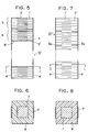
- Fig. 5 shows a second embodiment of the piezoelectric actuator element utilizing the thermosetting resin of epoxy group as the filler
- Fig. 6 is a cross-sectional view of the piezoelectric actuator element as shown in Fig. 5 which is taken along a line I-I.
- the same elements as those of the first embodiment as shown in Fig. 1 are represented by the same reference numerals.
- the piezoelectric actuator element 10′ of this embodiment comprises plural (e.g. 10) laminated piezoelectric subunits 5 each having a 3 mm X 3 mm area and a 0.5 mm thickness.
- Each of the piezoelectric subunits 5 comprises plural (e.g. 23) piezoelectric ceramic layers 1 each having an area of 3.0 mm X 3.0 mm and a thickness of 20 microns and internal electrode layers 2 each comprising an internal electrode 2a (2b) having an area of 2.5 mm X 2.5 mm and a thickness of 2 microns, the piezoelectric ceramic layers 1 and the internal electrode layers 2 being alternately laminated on one another in the same manner as that of the first embodiment.
- the external electrodes and the external electrode connecting members are integrally formed as external electroles 4′, but they may be formed separately from each other as the external electrodes and the external electrode connecting members like the first embodiment.
- the internal electrodes 2a (2c) of this embodiment are also connected to the external electrodes 4 through the internal electrode drawing portions (drawing electrodes) 2c (1c).
- the neighboring piezoelectric subunits 5 are attached through the adhesive member 3 such as the thermosetting organic adhesive, the glass having a low melting point, the soldering agent, or the piezoelectric ceramic material as described above.
- the adhesive member 3 has an area equal to or smaller than that of each internal electrode 2 a (2c), for example, a 2.5 mm X 2.5 mm area and a 10-micron thickness, and the thermosetting resin of epoxy group is filled as a filler 9′ into the slit portions 9 in such a manner as to surround the adhesive member 3.
- the piezoelectric actuator element 10′ (first element) thus constructed was applied with 60 volts, a displacement of 6.3 microns was obtained.
- a piezoelectric actuator element (second element) having no filler 9′ provided a displacement of 7.0 microns
- a piezoelectric actuator element (third element) having no filler and no adhesive member (the subunits were wholly and directly attached to each other) provided a displacement of 4.8 microns.
- the tensile strength was measured to be 4.0 kgf (39.2N), 3.2 kgf (31.4N) and 4.6 kgf (45.1N) for the first, second and third elements, respectively.
- Fig. 7 shows a third embodiment of the piezoelectric actuator element utilizing the filler as described above, in which all of the piezoelectric ceramic layers and the internal electrode layers 2 are integrally formed to form the piezoelectric actuator element. That is, the piezoelectric actuator element of this embodiment is produced not by laminating individually-formed plural piezoelectric subunits and then assembling them with the adhesive member, but by integrally laminating piezoelectric ceramic layers and internal electrode layers to directly form the piezoelectric actuator element.
- the piezoelectric actuator element 10" of this embodiment has an integration type of laminate structure in which piezoelectric ceramic layers 1′ each having a thickness of approximately 30 microns and internal electrode layers each having 3 microns are alternately laminated on each other, and includes slit portions 3a formed at a predetermined distance (every nine piezoelectric layers each of which comprises a piezoelectric ceramic layer and an internal electrode layer) in a laminating direction in such a manner as to surround the piezoelectric ceramic layers as shown in Fig. 8.
- the laminated internal electrode layers 2′ are connected alternately to two groups of external electrodes (positive and negative external electrodes) 4′ located at both sides of the piezoelectric actuator element 10".
- the odd-numbered internal electrode layers are connected to the (e.g. positive) external electrode 4′ located at the left side of the piezoelectric actuator element 10" while the even-numbered internal electrode layers are connected to the (e.g. negative) external electrode 4′ located at the right side of the piezoelectric actuator element 10".
- Each of the slit portions 3a is formed in the piezoelectric actuator element 10" in such a manner that an inner boundary (periphery) of each slit portion 3a has the same shape as the square internal electrode and the boundaries of the slit portion 3a and the internal electrode are over-lapped with each other. Further, the filler 9′ formed of thermosetting resin of epoxy group is filled in the slit portions 3a as shown in Fig. 8.
- a piezoelectric actuator element 10" (first element) having a apparent dimension of 6 mm X 6 mm X 10 mm was used, in which the internal electrode had an area of 5.5 mm X 5.5 mm, and the piezoelectrically-inactive portions and the slit portions had approximately 0.25 micron width and 10-micron thickness.
- a piezoelectric actuator element (second element) having the same structure and no filler 9′ and a piezoelectric actuator element (third element) having the same structure and no slit portion were also measured.
- the piezoelectric actuator element having the filler 9′ is slightly inferior in displacement value to the piezoelectric actuator element having no filler 9′, it is superior over the conventional piezoelectric actuator element having no slit portion. Further, the piezoelectric actuator element having the filler is superior in tensile strength over the piezoelectric actuator element having no filler.
- Fig. 9 shows an embodiment of a driving unit for driving a printing wire of a printer, in which the piezoelectric actuator element is used as a driving source.
- the driving unit 20 includes am U-shaped body frame 22 formed of Invar alloy whose linear expansion coefficient is 2.0 ppm/°C at a temperature ranging from room temperature to 100 °C.
- a leaf spring 26 is provided at one of hand portions of the U-shaped body frame 22, and formed integrally with both of another leaf spring 27 provided in parallel with the leaf spring 26 and a slant-moving member 28 in an inverse U-shaped form.
- the leaf spring 27 is connected to a moving member 25.
- a longitudinal effect type of laminate piezoelectric actuator element 21 of this invention is mounted below the moving member 25, and a wedge-shaped pre-load member 32 of aluminum is provided below the piezoelectric actuator element 21 to provide the piezoelectric actuator element 21 with a pre-load and compensate for difference in expansion coefficient due to temperature change.
- the slant-moving member 28 is equipped with a slant-moving arm 30, and a printing wire 31 is provided to a pointed end of the slant-moving arm 30.
- the moving member 25 is upwardly moved by expansion of the piezoelectric actuator element 21 with a piezoelectric or electrostrictive effect in the laminating or longitudinal direction.
- both of the leaf springs 26 and 27 are deformed and then the slant-moving member 28 is counterclockwise slanted, and the slant-moving arm 30 is also counterclockwise slanted, so that the printing wire 31 is upwardly moved to thereby perform a printing operation.
- the laminate piezoelectric actuator element of this invention has high reliability, and can be driven with a low driving voltage. Therefore, for example, when the laminate piezoelectric actuator element of this invention is used as a driving source of a impact type piezoelectric printer head, a driving voltage is remarkably decreased, and thus a power source is commonly used with a motor for driving other elements. As a result, miniaturization of a printer apparatus and decrease in cost can be performed.
- the laminate piezoelectric actuator element has a piezoelectrically-inactive portion including no internal electrode layer at the peripheral portion thereof, and thus reliability of insulation between internal electrode layers is high, and resistance against humidity is excellent.
- the laminate piezoelectric actuator element of this invention is designed so that the area of the adhesive member for attaching the neighboring piezoelectric subunits therethrough is equal or smaller than the area of the internal electrode to form a slit portion at the peripheral portion of the adhesive member, and a restrictive action of the piezoelectrically-inactive portion on the displacing motion of the piezoelectric actuator element is depressed.
- the piezoelectric actuator element is protected from being broken down.
- the piezoelectric actuator element of this invention may be filled with a filler into the slit portions, so that the mechanical strength thereof is not prevented from being depressed due to the presence of the slit portions.
Landscapes
- General Electrical Machinery Utilizing Piezoelectricity, Electrostriction Or Magnetostriction (AREA)
Applications Claiming Priority (8)
| Application Number | Priority Date | Filing Date | Title |
|---|---|---|---|
| JP2069504A JPH03270085A (ja) | 1990-03-19 | 1990-03-19 | 積層圧電アクチュエータ素子 |
| JP69504/90 | 1990-03-19 | ||
| JP22763590A JPH04107151A (ja) | 1990-08-28 | 1990-08-28 | 積層圧電アクチュエータ素子 |
| JP227635/90 | 1990-08-28 | ||
| JP2256083A JPH04133482A (ja) | 1990-09-26 | 1990-09-26 | スリット構造積層縦効果圧電素子 |
| JP256083/90 | 1990-09-26 | ||
| JP2294582A JPH04167580A (ja) | 1990-10-31 | 1990-10-31 | 積層圧電アクチュエータ素子 |
| JP294582/90 | 1990-10-31 |
Publications (3)
| Publication Number | Publication Date |
|---|---|
| EP0448349A2 true EP0448349A2 (fr) | 1991-09-25 |
| EP0448349A3 EP0448349A3 (en) | 1992-01-22 |
| EP0448349B1 EP0448349B1 (fr) | 1996-05-15 |
Family
ID=27465141
Family Applications (1)
| Application Number | Title | Priority Date | Filing Date |
|---|---|---|---|
| EP91302363A Expired - Lifetime EP0448349B1 (fr) | 1990-03-19 | 1991-03-19 | Elément d'actionnement piézoélectrique du type laminé |
Country Status (3)
| Country | Link |
|---|---|
| US (1) | US5089739A (fr) |
| EP (1) | EP0448349B1 (fr) |
| DE (1) | DE69119460T2 (fr) |
Cited By (11)
| Publication number | Priority date | Publication date | Assignee | Title |
|---|---|---|---|---|
| EP0536637A3 (en) * | 1991-10-09 | 1993-07-28 | Fujitsu Limited | Piezo-electric device type actuator |
| WO1997026681A1 (fr) * | 1996-01-18 | 1997-07-24 | Philips Electronics N.V. | Element piezo-electrique multicouche composite et procede de fabrication dudit element |
| WO1997040536A1 (fr) * | 1996-04-19 | 1997-10-30 | Siemens Aktiengesellschaft | Actionneur piezo multicouche monolithique, et son procede de production |
| WO2006077245A1 (fr) * | 2005-01-21 | 2006-07-27 | Siemens Aktiengesellschaft | Actionneur multicouche monolithique et procede pour sa production |
| EP1767770A1 (fr) * | 2005-09-27 | 2007-03-28 | Robert Bosch Gmbh | Actionneur piézo-électrique |
| EP1814170A3 (fr) * | 2006-01-27 | 2008-07-09 | Ngk Insulators, Ltd. | Actionneur piézo-electrique/électrostrictif |
| EP2043171A3 (fr) * | 2007-09-27 | 2010-01-27 | Robert Bosch GmbH | Module de piézoactionneur comprenant plusieurs piézoactionneurs reliés ensembles et son procédé de fabrication |
| EP2043170A3 (fr) * | 2007-09-27 | 2010-01-27 | Robert Bosch GmbH | Module de piézoactionneur comprenant plusieurs piézoactionneurs reliés ensembles et son procédé de fabrication |
| EP1898476A4 (fr) * | 2005-06-15 | 2012-03-28 | Kyocera Corp | Élément piézoélectrique multicouche et éjecteur utilisant ce dernier |
| CN113508471A (zh) * | 2019-02-08 | 2021-10-15 | Pi 陶瓷有限责任公司 | 用于制造压电叠堆执行器的方法和压电叠堆执行器 |
| CN117533020A (zh) * | 2023-11-30 | 2024-02-09 | 珠海纳思达企业管理有限公司 | 再生带头墨盒及回收方法、芯片 |
Families Citing this family (35)
| Publication number | Priority date | Publication date | Assignee | Title |
|---|---|---|---|---|
| JPH04214686A (ja) * | 1990-10-05 | 1992-08-05 | Nec Corp | 電歪効果素子 |
| JPH04159785A (ja) * | 1990-10-23 | 1992-06-02 | Nec Corp | 電歪効果素子 |
| DE4201937C2 (de) * | 1991-01-25 | 1997-05-22 | Murata Manufacturing Co | Piezoelektrisches laminiertes Stellglied |
| US5175465A (en) * | 1991-10-18 | 1992-12-29 | Aura Systems, Inc. | Piezoelectric and electrostrictive actuators |
| US6050679A (en) * | 1992-08-27 | 2000-04-18 | Hitachi Koki Imaging Solutions, Inc. | Ink jet printer transducer array with stacked or single flat plate element |
| US20070091230A1 (en) * | 1993-12-21 | 2007-04-26 | 3M Innovative Properties Company | Display incorporating reflective polarizer |
| JPH07335951A (ja) * | 1994-06-14 | 1995-12-22 | Philips Japan Ltd | 圧電アクチュエータ |
| EP0784349B1 (fr) * | 1996-01-11 | 2005-06-01 | Wac Data Services Co. Ltd. | Organe d'actionnement piezoélectrique laminé et procédé d'opération |
| DE19817802B4 (de) * | 1996-11-12 | 2009-08-06 | Marco Systemanalyse Und Entwicklung Gmbh | Piezoaktuatorisches Antriebs- oder Verstellelement |
| EP1061591A4 (fr) * | 1998-12-18 | 2007-05-02 | Denso Corp | Corps multicouche piezoelectrique |
| US6265139B1 (en) * | 1998-12-30 | 2001-07-24 | Samsung Electro-Mechanics Co., Ltd. | Method for fabricating piezoelectric/electrostrictive ceramic micro actuator using photolithography |
| DE19928176A1 (de) * | 1999-06-19 | 2001-01-04 | Bosch Gmbh Robert | Piezoaktor |
| DE10234787C1 (de) * | 2002-06-07 | 2003-10-30 | Pi Ceramic Gmbh Keramische Tec | Verfahren zur Herstellung eines monolithischen Vielschichtaktors, monolithischer Vielschichtaktor aus einem piezokeramischen oder elektrostriktiven Material |
| DE10307825A1 (de) * | 2003-02-24 | 2004-09-09 | Epcos Ag | Elektrisches Vielschichtbauelement und Schichtstapel |
| JP4258238B2 (ja) * | 2003-03-13 | 2009-04-30 | 株式会社デンソー | 積層型圧電素子及びその製造方法 |
| KR100849155B1 (ko) * | 2003-11-20 | 2008-07-30 | 바이킹 테크놀러지스, 엘.씨. | 전기-기계식 액추에이터를 위한 통합적 열 보상 장치 및방법 |
| JP2005294761A (ja) * | 2004-04-05 | 2005-10-20 | Tdk Corp | 積層型圧電素子 |
| JP4569153B2 (ja) * | 2004-04-14 | 2010-10-27 | 株式会社デンソー | 積層型圧電素子及び、その製造方法 |
| DE602005027914D1 (de) * | 2005-09-16 | 2011-06-16 | Delphi Tech Holding Sarl | Piezoelektrischer Aktor |
| US7443080B2 (en) * | 2006-01-23 | 2008-10-28 | Ngk Insulators, Ltd. | Laminated piezoelectric/electrostrictive device |
| WO2008017655A1 (fr) * | 2006-08-09 | 2008-02-14 | Continental Automotive Gmbh | Actionneur multicouche en céramique piézoélectrique à haute fiabilité |
| EP1978569B1 (fr) * | 2007-02-19 | 2011-11-30 | Siemens Aktiengesellschaft | Actionneur multicouche en piézocéramique et son procédé de fabrication |
| EP1978568B1 (fr) * | 2007-02-19 | 2011-10-12 | Siemens Aktiengesellschaft | Actionneur multicouche piézocéramique et procédé de fabrication de celui-ci |
| EP1978567B1 (fr) * | 2007-02-19 | 2014-06-25 | Continental Automotive GmbH | Actionneur multicouche en piézocéramique et son procédé de fabrication |
| JP2008218864A (ja) * | 2007-03-07 | 2008-09-18 | Denso Corp | 積層型圧電体素子 |
| JP2009076760A (ja) | 2007-09-21 | 2009-04-09 | Denso Corp | 積層型圧電素子及びその製造方法 |
| JP5029692B2 (ja) * | 2007-10-16 | 2012-09-19 | 株式会社村田製作所 | 圧電ポンプ |
| JP5584066B2 (ja) * | 2010-09-14 | 2014-09-03 | 太陽誘電株式会社 | 積層型圧電構造体 |
| US9070880B2 (en) | 2010-12-23 | 2015-06-30 | Lockheed Martin Corporation | Method of manufacturing a tape cast multilayer sonar transducer |
| JP5472218B2 (ja) * | 2011-06-30 | 2014-04-16 | Tdk株式会社 | 圧電素子 |
| JP2017034527A (ja) * | 2015-08-04 | 2017-02-09 | セイコーエプソン株式会社 | 圧電素子、プローブ、超音波測定装置、電子機器、分極処理方法、及び、初期化装置 |
| WO2017142486A1 (fr) * | 2016-02-19 | 2017-08-24 | National University Of Singapore | Capteur pour mesure de charge |
| DE102016110209B3 (de) * | 2016-06-02 | 2017-11-02 | Physik Instrumente (Pi) Gmbh & Co. Kg | Verfahren zum Verbinden eines keramischen Friktionselements mit einem piezokeramischen Element |
| US10312429B2 (en) * | 2016-07-28 | 2019-06-04 | Eyob Llc | Magnetoelectric macro fiber composite fabricated using low temperature transient liquid phase bonding |
| GB201617171D0 (en) | 2016-10-10 | 2016-11-23 | Universitetet I Troms� - Norges Arktiske Universitet | Piezoelectric films |
Family Cites Families (9)
| Publication number | Priority date | Publication date | Assignee | Title |
|---|---|---|---|---|
| US3649857A (en) * | 1970-07-30 | 1972-03-14 | Ibm | Mechanical energy storage and release device |
| DE3330538A1 (de) * | 1983-08-24 | 1985-03-14 | Siemens AG, 1000 Berlin und 8000 München | Piezoelektrisches stellglied |
| JPS6086880A (ja) * | 1983-10-19 | 1985-05-16 | Nec Corp | 電歪効果素子 |
| JPS60229380A (ja) * | 1984-04-27 | 1985-11-14 | Yokogawa Hokushin Electric Corp | セラミツクアクチユエ−タ |
| US4632856A (en) * | 1985-02-06 | 1986-12-30 | Marcus Michael A | Multilayer thin film electrical devices free of adhesive |
| JPS61206281A (ja) * | 1985-03-08 | 1986-09-12 | Toshiba Corp | 圧電変位素子 |
| DE3530383A1 (de) * | 1985-08-24 | 1987-03-05 | Reifenhaeuser Masch | Formgebendes werkzeugaggregat fuer eine strangpressvorrichtung fuer thermoplastifizierten kunststoff |
| JPH0217860U (fr) * | 1988-07-20 | 1990-02-06 | ||
| US4932119A (en) * | 1989-03-28 | 1990-06-12 | Litton Systems, Inc. | Method of making standard electrodisplacive transducers for deformable mirrors |
-
1991
- 1991-03-15 US US07/669,982 patent/US5089739A/en not_active Expired - Lifetime
- 1991-03-19 DE DE69119460T patent/DE69119460T2/de not_active Expired - Fee Related
- 1991-03-19 EP EP91302363A patent/EP0448349B1/fr not_active Expired - Lifetime
Cited By (15)
| Publication number | Priority date | Publication date | Assignee | Title |
|---|---|---|---|---|
| EP0536637A3 (en) * | 1991-10-09 | 1993-07-28 | Fujitsu Limited | Piezo-electric device type actuator |
| WO1997026681A1 (fr) * | 1996-01-18 | 1997-07-24 | Philips Electronics N.V. | Element piezo-electrique multicouche composite et procede de fabrication dudit element |
| US5841216A (en) * | 1996-01-18 | 1998-11-24 | U.S. Philips Corporation | Composite piezoelectric multilayer element and method of manufacturing such an element |
| WO1997040536A1 (fr) * | 1996-04-19 | 1997-10-30 | Siemens Aktiengesellschaft | Actionneur piezo multicouche monolithique, et son procede de production |
| US6260248B1 (en) | 1996-04-19 | 2001-07-17 | Siemens Aktiengesellschaft | Method for producing a monolithic multilayer piezo actuator |
| WO2006077245A1 (fr) * | 2005-01-21 | 2006-07-27 | Siemens Aktiengesellschaft | Actionneur multicouche monolithique et procede pour sa production |
| EP1898476A4 (fr) * | 2005-06-15 | 2012-03-28 | Kyocera Corp | Élément piézoélectrique multicouche et éjecteur utilisant ce dernier |
| US8648517B2 (en) | 2005-06-15 | 2014-02-11 | Kyocera Corporation | Multilayer piezoelectric element and injector using the same |
| US8441174B2 (en) | 2005-06-15 | 2013-05-14 | Kyocera Corporation | Multilayer piezoelectric element and injector using the same |
| EP1767770A1 (fr) * | 2005-09-27 | 2007-03-28 | Robert Bosch Gmbh | Actionneur piézo-électrique |
| EP1814170A3 (fr) * | 2006-01-27 | 2008-07-09 | Ngk Insulators, Ltd. | Actionneur piézo-electrique/électrostrictif |
| EP2043170A3 (fr) * | 2007-09-27 | 2010-01-27 | Robert Bosch GmbH | Module de piézoactionneur comprenant plusieurs piézoactionneurs reliés ensembles et son procédé de fabrication |
| EP2043171A3 (fr) * | 2007-09-27 | 2010-01-27 | Robert Bosch GmbH | Module de piézoactionneur comprenant plusieurs piézoactionneurs reliés ensembles et son procédé de fabrication |
| CN113508471A (zh) * | 2019-02-08 | 2021-10-15 | Pi 陶瓷有限责任公司 | 用于制造压电叠堆执行器的方法和压电叠堆执行器 |
| CN117533020A (zh) * | 2023-11-30 | 2024-02-09 | 珠海纳思达企业管理有限公司 | 再生带头墨盒及回收方法、芯片 |
Also Published As
| Publication number | Publication date |
|---|---|
| EP0448349A3 (en) | 1992-01-22 |
| US5089739A (en) | 1992-02-18 |
| DE69119460T2 (de) | 1996-10-31 |
| EP0448349B1 (fr) | 1996-05-15 |
| DE69119460D1 (de) | 1996-06-20 |
Similar Documents
| Publication | Publication Date | Title |
|---|---|---|
| EP0448349B1 (fr) | Elément d'actionnement piézoélectrique du type laminé | |
| US6441537B1 (en) | Piezoelectric/electrostrictive actuator having at least one piezoelectric/electrostrictive film | |
| US6534898B1 (en) | Piezoelectric/electrostrictive device having mutually opposing thin plate section | |
| CN101694865B (zh) | 叠层型压电元件及其制造方法 | |
| JP3120260B2 (ja) | 圧電/電歪膜型素子 | |
| EP0479328B1 (fr) | Organe d'actionnement piezoélectrique | |
| JP2842448B2 (ja) | 圧電/電歪膜型アクチュエータ | |
| US5208506A (en) | Laminated piezoelectric actuator | |
| JPH05267742A (ja) | 圧電/電歪膜型素子 | |
| US8941290B2 (en) | Vibrating body and vibration wave actuator | |
| US6404109B1 (en) | Piezoelectric/electrostrictive device having increased strength | |
| US6643902B2 (en) | Piezoelectric/electrostrictive device and method of manufacturing same | |
| US6498419B1 (en) | Piezoelectric/electrostrictive device having mutually opposing end surfaces and method of manufacturing the same | |
| CN102844900B (zh) | 喷墨头、使用喷墨头形成图像的方法、角速度传感器、使用角速度传感器测定角速度的方法、压电发电元件以及使用压电发电元件的发电方法 | |
| JP2001250996A (ja) | 圧電/電歪デバイス | |
| JPH04167580A (ja) | 積層圧電アクチュエータ素子 | |
| JPH03270085A (ja) | 積層圧電アクチュエータ素子 | |
| EP0350258B1 (fr) | Têtes d'impression matricielles par points | |
| JPH10284763A (ja) | 圧電アクチュエータ | |
| JPS6372171A (ja) | 電歪駆動体の製造方法 | |
| JP2003309298A (ja) | 圧電/電歪素子およびその製造方法 | |
| JPH11340535A (ja) | 積層型圧電アクチュエータ | |
| JP2706083B2 (ja) | 圧電アクチュエータ | |
| JP2533861B2 (ja) | 圧電アクチユエ−タ | |
| JPH04133482A (ja) | スリット構造積層縦効果圧電素子 |
Legal Events
| Date | Code | Title | Description |
|---|---|---|---|
| PUAI | Public reference made under article 153(3) epc to a published international application that has entered the european phase |
Free format text: ORIGINAL CODE: 0009012 |
|
| AK | Designated contracting states |
Kind code of ref document: A2 Designated state(s): DE FR GB |
|
| PUAL | Search report despatched |
Free format text: ORIGINAL CODE: 0009013 |
|
| AK | Designated contracting states |
Kind code of ref document: A3 Designated state(s): DE FR GB |
|
| 17P | Request for examination filed |
Effective date: 19920313 |
|
| 17Q | First examination report despatched |
Effective date: 19931026 |
|
| GRAA | (expected) grant |
Free format text: ORIGINAL CODE: 0009210 |
|
| AK | Designated contracting states |
Kind code of ref document: B1 Designated state(s): DE FR GB |
|
| ET | Fr: translation filed | ||
| REF | Corresponds to: |
Ref document number: 69119460 Country of ref document: DE Date of ref document: 19960620 |
|
| PGFP | Annual fee paid to national office [announced via postgrant information from national office to epo] |
Ref country code: GB Payment date: 19970310 Year of fee payment: 7 |
|
| PGFP | Annual fee paid to national office [announced via postgrant information from national office to epo] |
Ref country code: FR Payment date: 19970313 Year of fee payment: 7 |
|
| PLBE | No opposition filed within time limit |
Free format text: ORIGINAL CODE: 0009261 |
|
| STAA | Information on the status of an ep patent application or granted ep patent |
Free format text: STATUS: NO OPPOSITION FILED WITHIN TIME LIMIT |
|
| PGFP | Annual fee paid to national office [announced via postgrant information from national office to epo] |
Ref country code: DE Payment date: 19970401 Year of fee payment: 7 |
|
| 26N | No opposition filed | ||
| PG25 | Lapsed in a contracting state [announced via postgrant information from national office to epo] |
Ref country code: GB Free format text: LAPSE BECAUSE OF NON-PAYMENT OF DUE FEES Effective date: 19980319 |
|
| PG25 | Lapsed in a contracting state [announced via postgrant information from national office to epo] |
Ref country code: FR Free format text: THE PATENT HAS BEEN ANNULLED BY A DECISION OF A NATIONAL AUTHORITY Effective date: 19980331 |
|
| GBPC | Gb: european patent ceased through non-payment of renewal fee |
Effective date: 19980319 |
|
| PG25 | Lapsed in a contracting state [announced via postgrant information from national office to epo] |
Ref country code: DE Free format text: LAPSE BECAUSE OF NON-PAYMENT OF DUE FEES Effective date: 19981201 |
|
| REG | Reference to a national code |
Ref country code: FR Ref legal event code: ST |