EP0448423A1 - Entdeckungssystem fÀ¼r schlingernstabilisiertes Luftfahrzeug - Google Patents
Entdeckungssystem fÀ¼r schlingernstabilisiertes Luftfahrzeug Download PDFInfo
- Publication number
- EP0448423A1 EP0448423A1 EP91400422A EP91400422A EP0448423A1 EP 0448423 A1 EP0448423 A1 EP 0448423A1 EP 91400422 A EP91400422 A EP 91400422A EP 91400422 A EP91400422 A EP 91400422A EP 0448423 A1 EP0448423 A1 EP 0448423A1
- Authority
- EP
- European Patent Office
- Prior art keywords
- aircraft
- crown
- roll axis
- rotary
- window
- Prior art date
- Legal status (The legal status is an assumption and is not a legal conclusion. Google has not performed a legal analysis and makes no representation as to the accuracy of the status listed.)
- Granted
Links
Images




Classifications
-
- F—MECHANICAL ENGINEERING; LIGHTING; HEATING; WEAPONS; BLASTING
- F41—WEAPONS
- F41G—WEAPON SIGHTS; AIMING
- F41G7/00—Direction control systems for self-propelled missiles
- F41G7/20—Direction control systems for self-propelled missiles based on continuous observation of target position
- F41G7/22—Homing guidance systems
- F41G7/2253—Passive homing systems, i.e. comprising a receiver and do not requiring an active illumination of the target
-
- F—MECHANICAL ENGINEERING; LIGHTING; HEATING; WEAPONS; BLASTING
- F41—WEAPONS
- F41G—WEAPON SIGHTS; AIMING
- F41G7/00—Direction control systems for self-propelled missiles
- F41G7/20—Direction control systems for self-propelled missiles based on continuous observation of target position
- F41G7/22—Homing guidance systems
- F41G7/222—Homing guidance systems for spin-stabilized missiles
-
- F—MECHANICAL ENGINEERING; LIGHTING; HEATING; WEAPONS; BLASTING
- F41—WEAPONS
- F41G—WEAPON SIGHTS; AIMING
- F41G7/00—Direction control systems for self-propelled missiles
- F41G7/20—Direction control systems for self-propelled missiles based on continuous observation of target position
- F41G7/22—Homing guidance systems
- F41G7/2273—Homing guidance systems characterised by the type of waves
- F41G7/2293—Homing guidance systems characterised by the type of waves using electromagnetic waves other than radio waves
Definitions
- the present invention relates to a detection system for an aircraft stabilized in roll.
- the object of the present invention is to remedy these drawbacks. It relates to a detection system which comprises a limited number of detectors and which is particularly, although not exclusively, suitable for the self-protection of a missile flying at high altitude, vis-à-vis other ground / air or air missiles / air tending to destroy it.
- said rotary crown To detect an enemy which could be anywhere relative to the missile of the invention, it is advantageous for said rotary crown to rotate continuously around the roll axis of said aircraft. However, in the case where the enemy missile is necessarily on one side of the missile of the invention, it may be sufficient for said rotary crown to oscillate back and forth around the axis of roll of said aircraft. This is for example the case when the missile of the invention flies at very high altitude and must monitor enemy missiles arriving from below.
- said drive means said photosensitive means, said measurement means and said processing means, some are integral with said aircraft and others with said rotary ring, so that a device with a rotating joint or the like is provided for electrically supply said means and to connect them together.
- said crown may include a journaled shaft in the aircraft, it is preferable for said rotary crown to rotate around a shaft integral with said aircraft.
- said aircraft can be produced in two removable parts, nestable by means of said shaft.
- said rotary crown can be mounted on said shaft when said parts of the aircraft are dismantled.
- said rotary crown which can be produced in two parts which can be assembled around said shaft.
- said aircraft can be in one piece.
- the peripheral wall of said rotary crown is flush with the external face of the skin of said aircraft.
- the peripheral wall of said rotary crown is set back from the external face of the skin of said aircraft and the part of said skin opposite said rotary crown is made at least in part from a material transparent to radiation. to which said photosensitive means are sensitive.
- the external face of the skin of the aircraft can be continuous.
- said material transparent to radiation forms a complete crown of said skin of the aircraft.
- said transparent material may form only one segment of the crown of the skin of the aircraft, this segment corresponding to the maximum stroke of the rotating crown.
- said window includes an objective of the fish eye type making it possible to cover a field of 180 ° in the rotary plane passing through the center of said window and through the roll axis of said aircraft.
- said photosensitive means consist of several individual detectors and an observation window is associated with each of said individual detectors, the field scanned by each individual detector-window pair being part of the total field in the plane rotary passing through the center of said window and through the roll axis of said aircraft.
- Figure 1 shows, schematically, a missile according to the present invention, of which only the outer contour has been shown in phantom, while the rotary crown which it comprises is shown in solid lines.
- FIG. 2 is a diametral section through a plane passing through the roll axis of the missile, of the crown shown in FIG. 1.
- Figure 3 is a block diagram illustrating the detection system according to the invention, partly secured to the missile and partly secured to the crown.
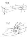
- FIG. 4 illustrates the operation of the system of FIGS. 1 to 3.
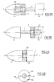
- FIGS. 5A and 5B illustrate two modes of mounting the rotary crown on the missile.
- FIGS. 6A and 6B illustrate an alternative embodiment of the mounting of the crown on the missile.
- FIGS. 7A, 7B and 7C illustrate alternative arrangements of the rotary crown in the missile.
- FIG. 8 is a cross section of the observation window provided in the rotary crown.
- FIG. 9 illustrates, in a view identical to FIG. 1, an alternative embodiment of the rotary crown.
- Figure 10 is a section of the crown of the system of Figure 9, by a plane orthogonal to the roll axis of the missile.
- Figures 11, 12 and 13 correspond respectively to sections along lines XI-XI, XII-XII and XIII-XIII of Figure 10.
- Figures 14, 15 and 16 show the system according to the present invention, mounted respectively on a satellite and aircraft.
- the missile 1, shown schematically in FIG. 1, is stabilized in roll around its longitudinal axis, or roll axis, L-L.
- the missile 1 comprises a hollow rotary crown 3, capable of turning around said roll axis L-L.
- the crown 3 comprises, near its center, bearings 7A.
- the crown 3 has an observation window 5, with a center 6.
- the crown 3 is rotatably mounted by means of the bearings 7A, on a shaft 7, integral with the missile 1.
- photosensitive means 8 arranged opposite the observation window 5.
- the photosensitive means 8 are for example produced in the form of bars or arrays of elements CCD type photosensitive, sensitive to infrared radiation.
- These photosensitive means are integral in rotation with the crown 3.
- the latter comprises a motor 9, integral in rotation with said crown, and rotating a pinion 10 meshing with a toothed wheel 11 integral of the shaft 7.
- the shaft 13 of the motor 9, on which the pinion 10 is wedged, is journalled in a frame 12 secured to the rotary crown 3.
- the shaft 13 is also secured to an indexing disc 14 cooperating with an angular position encoder 15, integral with the crown 3.
- An electrical supply device 16, integral with the missile 1, is provided for supplying the photosensitive means 8, the motor 9, as well as a device 17 for processing information, this device 17 being integral with the missile 1.
- a rotary joint or manifold device 18 is provided to allow the photosensitive means 8 and the motor 9 to be supplied from the supply device 16, as well as to transmit the information coming from the photosensitive means 8 to the processing device 17 and of the encoder 15.
- Figure 3 there is shown, in block diagram, the power supply and data transmission links between the devices 16 and 17 linked to the missile 1 and the devices 8, 9, 14 and 15 linked to the rotary crown 3. It has been shown that these connections pass through the rotary joint device or the like 18, and that the crown 3 was linked to the missile 1 by the drive 10, 11.
- the motor 9 is controlled to drive the crown 3 in rotation about the axis LL, either continuously over 180 °, or alternately back and forth, around from a middle position over an angular amplitude less than or equal to 180 °.
- the photosensitive means 8 are arranged so as to cover, in the axial plane passing through the center 6 of the observation window 5 and through the roll axis LL, a field A (see FIG. 1) of opening as close as possible 180 °.
- this field A Due to the rotation of this field A around the roll axis LL with the rotation of the crown 3, the field A scans, or the entire environment around the missile 1 (continuous rotation of the crown 3), or part of this environment (alternative rotation of said crown 3).
- the device 17, receiving the information from the photosensitive means 8 and from the angular position encoder 14, 15, is capable of determining the coordinates of any missile M located around the missile 1, by example in the form of the angular coordinates ⁇ and ⁇ illustrated in FIG. 4.
- the photosensitive means 8 indicate the position of the missile M in the field A
- the encoder 14, 15 indicates the position of the field A around the 'axis LL.
- the missile 1 is made up of two parts 1A and 1B which can be assembled together via the shaft 7.
- the shaft 7 is integral with the cylindrical part 1B and can enter a recess 20 provided in the conical part 1A.
- the shaft 7 was integral with the conical part 1A and could penetrate into a recess 21 in the cylindrical part 1B. In both cases, we sees that it is easy to arrange the crown 3 on the shaft 7 before assembling the two parts 1A and 1B.
- FIGS. 6A and 6B it has been assumed that the missile 1 was in one piece, while the crown 3 was composed of two half-crowns 3A and 3B, diametrically assembled by means of devices 22. In this case, we see that the crown can be easily put in place on the shaft 7 and assembled on it thanks to the device 22.
- FIG. 7A shows an embodiment of the system according to the present invention, in which the external peripheral wall 4 of the crown 3 is flush with the external face 30A of the skin 30 of the missile 1.
- transverse slots 31 appear on either side of the rotary crown 3.
- FIGS. 7B and 7C an embodiment has been shown in which the external peripheral wall 4 of the crown 3 is set back relative to the external wall 30A of the skin 30 of the missile.
- the part 32 of the skin 30 is formed by an omega transparent to the radiation to which the photosensitive elements are sensitive 8.
- this irdome constitutes a complete crown 32, as shown in FIG. 7B, or only part of the crown 33, as shown in FIG. 7C.
- the observation window 5 is advantageous for the observation window 5 to be constituted by an objective 34 in the shape of a fish eye, allowing the field A to cover 180 °.
- FIGS. 9 to 13 several observation windows 35, 36 and 37 are provided in the external peripheral wall 4 of the crown 3. At each of these observation windows 35, 36 and 37 are associated photosensitive means respectively bearing the references 38, 39 and 40.
- the window 35 couple - photosensitive means 38 is oriented towards the front of the missile, to embrace part A1 of the field A.
- the window couple 37 - photosensitive means 40 is oriented towards the rear of the missile to embrace part A3 of field A.
- the pair of window 36 - photosensitive means 39 is oriented so as to embrace the middle part A2 of field A.
- FIG. 14 there is shown an artificial satellite 41 having a rotating ring 3, as described above, rotating around its roll axis L-L.
- FIGS. 15 and 16 an observation plane 42 and a combat aircraft 43 are respectively shown, comprising a crown 3 rotating around their roll axis.
Landscapes
- Engineering & Computer Science (AREA)
- Chemical & Material Sciences (AREA)
- Combustion & Propulsion (AREA)
- General Engineering & Computer Science (AREA)
- Physics & Mathematics (AREA)
- Electromagnetism (AREA)
- Length Measuring Devices By Optical Means (AREA)
- Aiming, Guidance, Guns With A Light Source, Armor, Camouflage, And Targets (AREA)
- Length Measuring Devices With Unspecified Measuring Means (AREA)
Applications Claiming Priority (2)
| Application Number | Priority Date | Filing Date | Title |
|---|---|---|---|
| FR9003410A FR2659747B1 (fr) | 1990-03-16 | 1990-03-16 | Systeme de detection pour aeronef stabilise en roulis. |
| FR9003410 | 1990-03-16 |
Publications (2)
| Publication Number | Publication Date |
|---|---|
| EP0448423A1 true EP0448423A1 (de) | 1991-09-25 |
| EP0448423B1 EP0448423B1 (de) | 1994-12-21 |
Family
ID=9394833
Family Applications (1)
| Application Number | Title | Priority Date | Filing Date |
|---|---|---|---|
| EP91400422A Expired - Lifetime EP0448423B1 (de) | 1990-03-16 | 1991-02-18 | Entdeckungssystem für schlingernstabilisiertes Luftfahrzeug |
Country Status (6)
| Country | Link |
|---|---|
| US (1) | US5381139A (de) |
| EP (1) | EP0448423B1 (de) |
| CA (1) | CA2038373C (de) |
| DE (1) | DE69106018T2 (de) |
| ES (1) | ES2067879T3 (de) |
| FR (1) | FR2659747B1 (de) |
Cited By (1)
| Publication number | Priority date | Publication date | Assignee | Title |
|---|---|---|---|---|
| FR2867867A1 (fr) * | 2004-03-19 | 2005-09-23 | Thales Sa | Systeme aeroporte avec mecanisme de contre-roulis |
Families Citing this family (2)
| Publication number | Priority date | Publication date | Assignee | Title |
|---|---|---|---|---|
| US7113779B1 (en) | 2004-01-08 | 2006-09-26 | Iwao Fujisaki | Carrier |
| US10345087B2 (en) * | 2017-08-01 | 2019-07-09 | BAE Systems Informaticn and Electronic Systems Integration Inc. | Mid body seeker payload |
Citations (7)
| Publication number | Priority date | Publication date | Assignee | Title |
|---|---|---|---|---|
| US2873381A (en) * | 1957-08-29 | 1959-02-10 | Thomas J Lauroesch | Rotary scanning device |
| GB1511643A (en) * | 1960-07-13 | 1978-05-24 | Dehavilland Aircraft | Missiles |
| US4142696A (en) * | 1962-02-27 | 1979-03-06 | Novatronics, Inc. | Guidance devices |
| US4193688A (en) * | 1970-10-28 | 1980-03-18 | Raytheon Company | Optical scanning system |
| GB2162014A (en) * | 1984-07-21 | 1986-01-22 | Messerschmitt Boelkow Blohm | Navigation and flight guidance |
| GB2190177A (en) * | 1986-05-06 | 1987-11-11 | Diehl Gmbh & Co | A proximity detonation device |
| WO1988004400A1 (fr) * | 1986-12-08 | 1988-06-16 | Bernard Baudrous | Guidage par infra-rouge simplifie pour tout projectile |
Family Cites Families (6)
| Publication number | Priority date | Publication date | Assignee | Title |
|---|---|---|---|---|
| SE396136B (sv) * | 1974-06-25 | 1977-09-05 | Bofors Ab | Passivt ir-zonror |
| US3942446A (en) * | 1974-09-06 | 1976-03-09 | The United States Of America As Represented By The Secretary Of The Army | Optical fuze and/or miss distance indicator |
| US3924826A (en) * | 1974-12-20 | 1975-12-09 | Us Air Force | Rotatable window means |
| US4044251A (en) * | 1976-05-18 | 1977-08-23 | Minnesota Mining And Manufacturing Company | Electromagnetic radiation detector with large area sensing medium |
| US4527158A (en) * | 1982-07-29 | 1985-07-02 | Runnels Russell W | Aircraft collision pilot warning indicating system |
| US4755818A (en) * | 1986-08-15 | 1988-07-05 | The United States Of America As Represented By The Secretary Of The Army | Aircraft collision warning system |
-
1990
- 1990-03-16 FR FR9003410A patent/FR2659747B1/fr not_active Expired - Fee Related
-
1991
- 1991-02-18 DE DE69106018T patent/DE69106018T2/de not_active Expired - Fee Related
- 1991-02-18 EP EP91400422A patent/EP0448423B1/de not_active Expired - Lifetime
- 1991-02-18 ES ES91400422T patent/ES2067879T3/es not_active Expired - Lifetime
- 1991-03-15 CA CA002038373A patent/CA2038373C/fr not_active Expired - Fee Related
-
1993
- 1993-01-06 US US08/001,212 patent/US5381139A/en not_active Expired - Lifetime
Patent Citations (7)
| Publication number | Priority date | Publication date | Assignee | Title |
|---|---|---|---|---|
| US2873381A (en) * | 1957-08-29 | 1959-02-10 | Thomas J Lauroesch | Rotary scanning device |
| GB1511643A (en) * | 1960-07-13 | 1978-05-24 | Dehavilland Aircraft | Missiles |
| US4142696A (en) * | 1962-02-27 | 1979-03-06 | Novatronics, Inc. | Guidance devices |
| US4193688A (en) * | 1970-10-28 | 1980-03-18 | Raytheon Company | Optical scanning system |
| GB2162014A (en) * | 1984-07-21 | 1986-01-22 | Messerschmitt Boelkow Blohm | Navigation and flight guidance |
| GB2190177A (en) * | 1986-05-06 | 1987-11-11 | Diehl Gmbh & Co | A proximity detonation device |
| WO1988004400A1 (fr) * | 1986-12-08 | 1988-06-16 | Bernard Baudrous | Guidage par infra-rouge simplifie pour tout projectile |
Cited By (2)
| Publication number | Priority date | Publication date | Assignee | Title |
|---|---|---|---|---|
| FR2867867A1 (fr) * | 2004-03-19 | 2005-09-23 | Thales Sa | Systeme aeroporte avec mecanisme de contre-roulis |
| WO2005101152A1 (fr) * | 2004-03-19 | 2005-10-27 | Thales | Systeme aeroporte avec mecanisme de contre-roulis |
Also Published As
| Publication number | Publication date |
|---|---|
| FR2659747A1 (fr) | 1991-09-20 |
| FR2659747B1 (fr) | 1992-08-14 |
| DE69106018T2 (de) | 1995-05-04 |
| CA2038373C (fr) | 2001-10-16 |
| EP0448423B1 (de) | 1994-12-21 |
| US5381139A (en) | 1995-01-10 |
| ES2067879T3 (es) | 1995-04-01 |
| CA2038373A1 (fr) | 1991-09-17 |
| DE69106018D1 (de) | 1995-02-02 |
Similar Documents
| Publication | Publication Date | Title |
|---|---|---|
| EP3404481A1 (de) | Schutzvorrichtung eines optischen sensors, und entsprechendes lenkassistenzsystem | |
| FR3047346A1 (fr) | Bloc propulseur permettant l'affichage d'un message. | |
| EP0465282B1 (de) | Kugeldrehantrieb | |
| EP3010800A1 (de) | Drohne mit einer bildgebenden vorrichtung und mit mittel zum schutz der bildgebenden vorrichtung | |
| WO2013079657A1 (fr) | Piece d'horlogerie | |
| EP0448423B1 (de) | Entdeckungssystem für schlingernstabilisiertes Luftfahrzeug | |
| WO1998003882A1 (fr) | Systeme d'observation ou de visee | |
| EP2316731B1 (de) | Vorrichtung zur Vibrationsverringerung eines Drehflüglerrotors sowie Drehflügler mit einer solchen Vorrichtung | |
| FR3112120A1 (fr) | Ensemble de capture d'image et de detection d'obstacle destine a ëtre monte sur une plateforme telle qu'un drone et drone muni d'un tel ensemble de capture d'image et de detection d'obstacle | |
| EP0229681B1 (de) | Antriebsvorrichtung zum Drehen der Rolle eines Rolladens, Rollstores oder dergleichen | |
| EP1045588A1 (de) | Vorrichtung zur Übertragung von digitalen Videobildern | |
| WO2000002000A1 (fr) | Dispositif d'autoprotection passive pour engin mobile tel qu'un helicoptere | |
| EP0536048B1 (de) | Mine zur Flächenverteidigung | |
| WO2005110848A1 (fr) | Satellite, procede et flotte de satellites d'observation d'un corps celeste | |
| FR2629579A1 (fr) | Perfectionnements aux dispositifs d'observation pour engins militaires | |
| EP0567545B1 (de) | Vorrichtung zur ausrichtung und einstellung der position eines gegenstandes, insbesondere einer sende-/empfangsantenne für elektromagnetische wellern, in wenigstens einer von drei richtungen im raum | |
| EP0468890B1 (de) | Verschlussvorrichtung für einen Strahl, der einen bestimmten Punkt zu treffen hat | |
| CA2789462A1 (fr) | Turbopropulseur muni d'un dispositif d'orientation de pales | |
| BE1006654A5 (fr) | Dispositif de securite de prise de force sur tracteur agricole ou sur une autre machine avec arbre tournant. | |
| EP1635485A1 (de) | Optisches Übertragungsverfahren zwischen einem Terminal an Bord eines Raumfahrzeuges, und Raumfahrzeug für das Verfahren | |
| FR2725514A1 (fr) | Systeme gyroscopique pour missile en autorotation | |
| EP0418132B1 (de) | Gerät zur Ermittlung von Zielen | |
| FR2798460A1 (fr) | Tete offensive equipee d'une masse a elements actifs | |
| EP4538166A1 (de) | Selbstfahrende oder ferngesteuerte medienwechselmaschine | |
| FR3148547A1 (fr) | Engin roulant automoteur à déplacement automatique encore appelé robot |
Legal Events
| Date | Code | Title | Description |
|---|---|---|---|
| PUAI | Public reference made under article 153(3) epc to a published international application that has entered the european phase |
Free format text: ORIGINAL CODE: 0009012 |
|
| AK | Designated contracting states |
Kind code of ref document: A1 Designated state(s): BE CH DE ES GB IT LI NL SE |
|
| 17P | Request for examination filed |
Effective date: 19911114 |
|
| 17Q | First examination report despatched |
Effective date: 19940118 |
|
| GRAA | (expected) grant |
Free format text: ORIGINAL CODE: 0009210 |
|
| AK | Designated contracting states |
Kind code of ref document: B1 Designated state(s): BE CH DE ES GB IT LI NL SE |
|
| EAL | Se: european patent in force in sweden |
Ref document number: 91400422.1 |
|
| REF | Corresponds to: |
Ref document number: 69106018 Country of ref document: DE Date of ref document: 19950202 |
|
| GBT | Gb: translation of ep patent filed (gb section 77(6)(a)/1977) |
Effective date: 19950117 |
|
| ITF | It: translation for a ep patent filed | ||
| REG | Reference to a national code |
Ref country code: ES Ref legal event code: FG2A Ref document number: 2067879 Country of ref document: ES Kind code of ref document: T3 |
|
| NLT2 | Nl: modifications (of names), taken from the european patent patent bulletin |
Owner name: AEROSPATIALE SOCIETE NATIONALE INDUSTRIELLE |
|
| PLBE | No opposition filed within time limit |
Free format text: ORIGINAL CODE: 0009261 |
|
| STAA | Information on the status of an ep patent application or granted ep patent |
Free format text: STATUS: NO OPPOSITION FILED WITHIN TIME LIMIT |
|
| 26N | No opposition filed | ||
| REG | Reference to a national code |
Ref country code: GB Ref legal event code: IF02 |
|
| PGFP | Annual fee paid to national office [announced via postgrant information from national office to epo] |
Ref country code: CH Payment date: 20061229 Year of fee payment: 17 |
|
| PGFP | Annual fee paid to national office [announced via postgrant information from national office to epo] |
Ref country code: BE Payment date: 20070117 Year of fee payment: 17 |
|
| PGFP | Annual fee paid to national office [announced via postgrant information from national office to epo] |
Ref country code: DE Payment date: 20070131 Year of fee payment: 17 |
|
| PGFP | Annual fee paid to national office [announced via postgrant information from national office to epo] |
Ref country code: SE Payment date: 20070208 Year of fee payment: 17 |
|
| PGFP | Annual fee paid to national office [announced via postgrant information from national office to epo] |
Ref country code: GB Payment date: 20070214 Year of fee payment: 17 |
|
| PGFP | Annual fee paid to national office [announced via postgrant information from national office to epo] |
Ref country code: NL Payment date: 20070216 Year of fee payment: 17 |
|
| PGFP | Annual fee paid to national office [announced via postgrant information from national office to epo] |
Ref country code: ES Payment date: 20070226 Year of fee payment: 17 |
|
| REG | Reference to a national code |
Ref country code: CH Ref legal event code: PCAR Free format text: JOHN P. MUNZINGER C/O CRONIN INTELLECTUAL PROPERTY;CHEMIN DE PRECOSSY 31;1260 NYON (CH) |
|
| PGFP | Annual fee paid to national office [announced via postgrant information from national office to epo] |
Ref country code: IT Payment date: 20070607 Year of fee payment: 17 |
|
| BERE | Be: lapsed |
Owner name: *AEROSPATIALE SOC. NATIONALE INDUSTRIELLE Effective date: 20080228 |
|
| REG | Reference to a national code |
Ref country code: CH Ref legal event code: PL |
|
| EUG | Se: european patent has lapsed | ||
| GBPC | Gb: european patent ceased through non-payment of renewal fee |
Effective date: 20080218 |
|
| PG25 | Lapsed in a contracting state [announced via postgrant information from national office to epo] |
Ref country code: CH Free format text: LAPSE BECAUSE OF NON-PAYMENT OF DUE FEES Effective date: 20080229 Ref country code: LI Free format text: LAPSE BECAUSE OF NON-PAYMENT OF DUE FEES Effective date: 20080229 |
|
| NLV4 | Nl: lapsed or anulled due to non-payment of the annual fee |
Effective date: 20080901 |
|
| PG25 | Lapsed in a contracting state [announced via postgrant information from national office to epo] |
Ref country code: NL Free format text: LAPSE BECAUSE OF NON-PAYMENT OF DUE FEES Effective date: 20080901 |
|
| PG25 | Lapsed in a contracting state [announced via postgrant information from national office to epo] |
Ref country code: SE Free format text: LAPSE BECAUSE OF NON-PAYMENT OF DUE FEES Effective date: 20080219 Ref country code: DE Free format text: LAPSE BECAUSE OF NON-PAYMENT OF DUE FEES Effective date: 20080902 |
|
| PG25 | Lapsed in a contracting state [announced via postgrant information from national office to epo] |
Ref country code: BE Free format text: LAPSE BECAUSE OF NON-PAYMENT OF DUE FEES Effective date: 20080228 |
|
| REG | Reference to a national code |
Ref country code: ES Ref legal event code: FD2A Effective date: 20080219 |
|
| PG25 | Lapsed in a contracting state [announced via postgrant information from national office to epo] |
Ref country code: GB Free format text: LAPSE BECAUSE OF NON-PAYMENT OF DUE FEES Effective date: 20080218 |
|
| PG25 | Lapsed in a contracting state [announced via postgrant information from national office to epo] |
Ref country code: ES Free format text: LAPSE BECAUSE OF NON-PAYMENT OF DUE FEES Effective date: 20080219 |
|
| PG25 | Lapsed in a contracting state [announced via postgrant information from national office to epo] |
Ref country code: IT Free format text: LAPSE BECAUSE OF NON-PAYMENT OF DUE FEES Effective date: 20080218 |