EP0448423A1 - Detection system for roll stabilized airship - Google Patents
Detection system for roll stabilized airship Download PDFInfo
- Publication number
- EP0448423A1 EP0448423A1 EP91400422A EP91400422A EP0448423A1 EP 0448423 A1 EP0448423 A1 EP 0448423A1 EP 91400422 A EP91400422 A EP 91400422A EP 91400422 A EP91400422 A EP 91400422A EP 0448423 A1 EP0448423 A1 EP 0448423A1
- Authority
- EP
- European Patent Office
- Prior art keywords
- aircraft
- crown
- roll axis
- rotary
- window
- Prior art date
- Legal status (The legal status is an assumption and is not a legal conclusion. Google has not performed a legal analysis and makes no representation as to the accuracy of the status listed.)
- Granted
Links
Images




Classifications
-
- F—MECHANICAL ENGINEERING; LIGHTING; HEATING; WEAPONS; BLASTING
- F41—WEAPONS
- F41G—WEAPON SIGHTS; AIMING
- F41G7/00—Direction control systems for self-propelled missiles
- F41G7/20—Direction control systems for self-propelled missiles based on continuous observation of target position
- F41G7/22—Homing guidance systems
- F41G7/2253—Passive homing systems, i.e. comprising a receiver and do not requiring an active illumination of the target
-
- F—MECHANICAL ENGINEERING; LIGHTING; HEATING; WEAPONS; BLASTING
- F41—WEAPONS
- F41G—WEAPON SIGHTS; AIMING
- F41G7/00—Direction control systems for self-propelled missiles
- F41G7/20—Direction control systems for self-propelled missiles based on continuous observation of target position
- F41G7/22—Homing guidance systems
- F41G7/222—Homing guidance systems for spin-stabilized missiles
-
- F—MECHANICAL ENGINEERING; LIGHTING; HEATING; WEAPONS; BLASTING
- F41—WEAPONS
- F41G—WEAPON SIGHTS; AIMING
- F41G7/00—Direction control systems for self-propelled missiles
- F41G7/20—Direction control systems for self-propelled missiles based on continuous observation of target position
- F41G7/22—Homing guidance systems
- F41G7/2273—Homing guidance systems characterised by the type of waves
- F41G7/2293—Homing guidance systems characterised by the type of waves using electromagnetic waves other than radio waves
Definitions
- the present invention relates to a detection system for an aircraft stabilized in roll.
- the object of the present invention is to remedy these drawbacks. It relates to a detection system which comprises a limited number of detectors and which is particularly, although not exclusively, suitable for the self-protection of a missile flying at high altitude, vis-à-vis other ground / air or air missiles / air tending to destroy it.
- said rotary crown To detect an enemy which could be anywhere relative to the missile of the invention, it is advantageous for said rotary crown to rotate continuously around the roll axis of said aircraft. However, in the case where the enemy missile is necessarily on one side of the missile of the invention, it may be sufficient for said rotary crown to oscillate back and forth around the axis of roll of said aircraft. This is for example the case when the missile of the invention flies at very high altitude and must monitor enemy missiles arriving from below.
- said drive means said photosensitive means, said measurement means and said processing means, some are integral with said aircraft and others with said rotary ring, so that a device with a rotating joint or the like is provided for electrically supply said means and to connect them together.
- said crown may include a journaled shaft in the aircraft, it is preferable for said rotary crown to rotate around a shaft integral with said aircraft.
- said aircraft can be produced in two removable parts, nestable by means of said shaft.
- said rotary crown can be mounted on said shaft when said parts of the aircraft are dismantled.
- said rotary crown which can be produced in two parts which can be assembled around said shaft.
- said aircraft can be in one piece.
- the peripheral wall of said rotary crown is flush with the external face of the skin of said aircraft.
- the peripheral wall of said rotary crown is set back from the external face of the skin of said aircraft and the part of said skin opposite said rotary crown is made at least in part from a material transparent to radiation. to which said photosensitive means are sensitive.
- the external face of the skin of the aircraft can be continuous.
- said material transparent to radiation forms a complete crown of said skin of the aircraft.
- said transparent material may form only one segment of the crown of the skin of the aircraft, this segment corresponding to the maximum stroke of the rotating crown.
- said window includes an objective of the fish eye type making it possible to cover a field of 180 ° in the rotary plane passing through the center of said window and through the roll axis of said aircraft.
- said photosensitive means consist of several individual detectors and an observation window is associated with each of said individual detectors, the field scanned by each individual detector-window pair being part of the total field in the plane rotary passing through the center of said window and through the roll axis of said aircraft.
- Figure 1 shows, schematically, a missile according to the present invention, of which only the outer contour has been shown in phantom, while the rotary crown which it comprises is shown in solid lines.
- FIG. 2 is a diametral section through a plane passing through the roll axis of the missile, of the crown shown in FIG. 1.
- Figure 3 is a block diagram illustrating the detection system according to the invention, partly secured to the missile and partly secured to the crown.
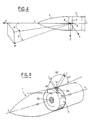
- FIG. 4 illustrates the operation of the system of FIGS. 1 to 3.
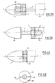
- FIGS. 5A and 5B illustrate two modes of mounting the rotary crown on the missile.
- FIGS. 6A and 6B illustrate an alternative embodiment of the mounting of the crown on the missile.
- FIGS. 7A, 7B and 7C illustrate alternative arrangements of the rotary crown in the missile.
- FIG. 8 is a cross section of the observation window provided in the rotary crown.
- FIG. 9 illustrates, in a view identical to FIG. 1, an alternative embodiment of the rotary crown.
- Figure 10 is a section of the crown of the system of Figure 9, by a plane orthogonal to the roll axis of the missile.
- Figures 11, 12 and 13 correspond respectively to sections along lines XI-XI, XII-XII and XIII-XIII of Figure 10.
- Figures 14, 15 and 16 show the system according to the present invention, mounted respectively on a satellite and aircraft.
- the missile 1, shown schematically in FIG. 1, is stabilized in roll around its longitudinal axis, or roll axis, L-L.
- the missile 1 comprises a hollow rotary crown 3, capable of turning around said roll axis L-L.
- the crown 3 comprises, near its center, bearings 7A.
- the crown 3 has an observation window 5, with a center 6.
- the crown 3 is rotatably mounted by means of the bearings 7A, on a shaft 7, integral with the missile 1.
- photosensitive means 8 arranged opposite the observation window 5.
- the photosensitive means 8 are for example produced in the form of bars or arrays of elements CCD type photosensitive, sensitive to infrared radiation.
- These photosensitive means are integral in rotation with the crown 3.
- the latter comprises a motor 9, integral in rotation with said crown, and rotating a pinion 10 meshing with a toothed wheel 11 integral of the shaft 7.
- the shaft 13 of the motor 9, on which the pinion 10 is wedged, is journalled in a frame 12 secured to the rotary crown 3.
- the shaft 13 is also secured to an indexing disc 14 cooperating with an angular position encoder 15, integral with the crown 3.
- An electrical supply device 16, integral with the missile 1, is provided for supplying the photosensitive means 8, the motor 9, as well as a device 17 for processing information, this device 17 being integral with the missile 1.
- a rotary joint or manifold device 18 is provided to allow the photosensitive means 8 and the motor 9 to be supplied from the supply device 16, as well as to transmit the information coming from the photosensitive means 8 to the processing device 17 and of the encoder 15.
- Figure 3 there is shown, in block diagram, the power supply and data transmission links between the devices 16 and 17 linked to the missile 1 and the devices 8, 9, 14 and 15 linked to the rotary crown 3. It has been shown that these connections pass through the rotary joint device or the like 18, and that the crown 3 was linked to the missile 1 by the drive 10, 11.
- the motor 9 is controlled to drive the crown 3 in rotation about the axis LL, either continuously over 180 °, or alternately back and forth, around from a middle position over an angular amplitude less than or equal to 180 °.
- the photosensitive means 8 are arranged so as to cover, in the axial plane passing through the center 6 of the observation window 5 and through the roll axis LL, a field A (see FIG. 1) of opening as close as possible 180 °.
- this field A Due to the rotation of this field A around the roll axis LL with the rotation of the crown 3, the field A scans, or the entire environment around the missile 1 (continuous rotation of the crown 3), or part of this environment (alternative rotation of said crown 3).
- the device 17, receiving the information from the photosensitive means 8 and from the angular position encoder 14, 15, is capable of determining the coordinates of any missile M located around the missile 1, by example in the form of the angular coordinates ⁇ and ⁇ illustrated in FIG. 4.
- the photosensitive means 8 indicate the position of the missile M in the field A
- the encoder 14, 15 indicates the position of the field A around the 'axis LL.
- the missile 1 is made up of two parts 1A and 1B which can be assembled together via the shaft 7.
- the shaft 7 is integral with the cylindrical part 1B and can enter a recess 20 provided in the conical part 1A.
- the shaft 7 was integral with the conical part 1A and could penetrate into a recess 21 in the cylindrical part 1B. In both cases, we sees that it is easy to arrange the crown 3 on the shaft 7 before assembling the two parts 1A and 1B.
- FIGS. 6A and 6B it has been assumed that the missile 1 was in one piece, while the crown 3 was composed of two half-crowns 3A and 3B, diametrically assembled by means of devices 22. In this case, we see that the crown can be easily put in place on the shaft 7 and assembled on it thanks to the device 22.
- FIG. 7A shows an embodiment of the system according to the present invention, in which the external peripheral wall 4 of the crown 3 is flush with the external face 30A of the skin 30 of the missile 1.
- transverse slots 31 appear on either side of the rotary crown 3.
- FIGS. 7B and 7C an embodiment has been shown in which the external peripheral wall 4 of the crown 3 is set back relative to the external wall 30A of the skin 30 of the missile.
- the part 32 of the skin 30 is formed by an omega transparent to the radiation to which the photosensitive elements are sensitive 8.
- this irdome constitutes a complete crown 32, as shown in FIG. 7B, or only part of the crown 33, as shown in FIG. 7C.
- the observation window 5 is advantageous for the observation window 5 to be constituted by an objective 34 in the shape of a fish eye, allowing the field A to cover 180 °.
- FIGS. 9 to 13 several observation windows 35, 36 and 37 are provided in the external peripheral wall 4 of the crown 3. At each of these observation windows 35, 36 and 37 are associated photosensitive means respectively bearing the references 38, 39 and 40.
- the window 35 couple - photosensitive means 38 is oriented towards the front of the missile, to embrace part A1 of the field A.
- the window couple 37 - photosensitive means 40 is oriented towards the rear of the missile to embrace part A3 of field A.
- the pair of window 36 - photosensitive means 39 is oriented so as to embrace the middle part A2 of field A.
- FIG. 14 there is shown an artificial satellite 41 having a rotating ring 3, as described above, rotating around its roll axis L-L.
- FIGS. 15 and 16 an observation plane 42 and a combat aircraft 43 are respectively shown, comprising a crown 3 rotating around their roll axis.
Landscapes
- Engineering & Computer Science (AREA)
- Chemical & Material Sciences (AREA)
- Combustion & Propulsion (AREA)
- General Engineering & Computer Science (AREA)
- Physics & Mathematics (AREA)
- Electromagnetism (AREA)
- Length Measuring Devices By Optical Means (AREA)
- Aiming, Guidance, Guns With A Light Source, Armor, Camouflage, And Targets (AREA)
- Length Measuring Devices With Unspecified Measuring Means (AREA)
Abstract
Description
La présente invention concerne un système de détection pour aéronef stabilisé en roulis.The present invention relates to a detection system for an aircraft stabilized in roll.
On sait que les aéronefs modernes sont pourvus de système de détection destinés à observer le terrain qu'ils survolent et/ou à détecter des aéronefs ennemis chargés de leur destruction.It is known that modern aircraft are equipped with detection systems intended to observe the terrain over which they pass and / or to detect enemy aircraft in charge of their destruction.
Par exemple, le brevet américain US-A-4 543 603 décrit un système de reconnaissance à missile dans lequel le balayage du champ observé est effectué grâce à la rotation dudit missile autour de son axe de roulis. Un tel système ne peut être mis en oeuvre pour un missile stabilisé en roulis.For example, American patent US-A-4,543,603 describes a missile recognition system in which the scanning of the observed field is carried out by virtue of the rotation of said missile around its roll axis. Such a system cannot be implemented for a missile stabilized in roll.
En revanche, le brevet américain US-A-3 942 446 concerne un système de détection d'aéronef ennemi pour un missile stabilisé en roulis. Dans ce système antérieur, on prévoit des couronnes de détecteurs disposées à la périphérie dudit missile. Pour pouvoir couvrir l'intégralité du champ autour de l'axe de roulis du missile, chaque couronne comporte une pluralité de détecteurs. De la multiplicité desdits détecteurs résulte un coût élevé du système et-une gestion complexe des informations émises par lesdits détecteurs.In contrast, American patent US-A-3,942,446 relates to an enemy aircraft detection system for a missile stabilized in roll. In this prior system, there are provided detector rings arranged at the periphery of said missile. To be able to cover the entire field around the roll axis of the missile, each ring has a plurality of detectors. The multiplicity of said detectors results in a high cost of the system and a complex management of the information transmitted by said detectors.
La présente invention a pour objet de remédier à ces inconvénients. Elle concerne un système de détection qui comporte un nombre limité de détecteurs et qui est particulièrement, quoique non exclusivement, approprié à l'autoprotection d'un missile volant à haute altitude, vis-à-vis d'autres missiles sol/air ou air/air tendant à le détruire.The object of the present invention is to remedy these drawbacks. It relates to a detection system which comprises a limited number of detectors and which is particularly, although not exclusively, suitable for the self-protection of a missile flying at high altitude, vis-à-vis other ground / air or air missiles / air tending to destroy it.
A cette fin, selon l'invention, le système de détection pour aéronef stabilisé en roulis, est remarquable en ce qu'il comporte :
- une couronne rotative creuse susceptible de tourner autour de l'axe de roulis dudit aéronef ;
- des moyens pour entraîner ladite couronne en rotation autour dudit axe de roulis ;
- des moyens photosensibles disposés à l'intérieur de ladite couronne rotative creuse et susceptibles d'observer l'environnement dudit aéronef à travers au moins une fenêtre d'observation ménagée dans la paroi périphérique externe de ladite couronne ;
- des moyens de mesure indiquant à chaque instant la position angulaire de ladite couronne autour dudit axe de roulis ; et
- des moyens de traitement recevant les informations délivrées par lesdits moyens photosensibles et par lesdits moyens de mesure.
- a hollow rotary crown capable of rotating around the roll axis of said aircraft;
- means for driving said crown in rotation about said roll axis;
- photosensitive means arranged inside said hollow rotary crown and capable of observing the environment of said aircraft through at least one observation window formed in the external peripheral wall of said crown;
- measuring means indicating at all times the angular position of said ring around said roll axis; and
- processing means receiving the information delivered by said photosensitive means and by said measurement means.
Ainsi, grâce au champ desdits moyens photosensibles dans un plan passant par le centre de ladite fenêtre et par l'axe de roulis de l'aéronef, il est possible d'effectuer une détection en gisement. Par ailleurs, à cause de la rotation de ce plan autour de l'axe de roulis, on obtient une détection en site.Thus, by virtue of the field of said photosensitive means in a plane passing through the center of said window and through the roll axis of the aircraft, it is possible to perform a detection in a field. Furthermore, because of the rotation of this plane around the roll axis, a detection in elevation is obtained.
On voit donc qu'il est suffisant, pour une détection en gisement et en site, que lesdits moyens photosensibles observent au moins le champ contenu dans ledit plan tournant passant par le centre de ladite fenêtre et par l'axe de roulis dudit aéronef.We therefore see that it is sufficient, for a detection in field and in site, that said photosensitive means observe at least the field contained in said rotating plane passing through the center of said window and through the roll axis of said aircraft.
Pour détecter un ennemi qui pourrait se trouver n'importe où par rapport au missile de l'invention, il est avantageux que ladite couronne rotative tourne de façon continue autour de l'axe de roulis dudit aéronef. Toutefois, dans le cas où le missile ennemi se trouve obligatoirement d'un seul côté du missile de l'invention, il peut être suffisant que ladite couronne rotative oscille d'un mouvement alternatif de va-et-vient autour de l'axe de roulis dudit aéronef. Ceci est par exemple le cas lorsque le missile de l'invention vole à très haute altitude et doit surveiller des missiles ennemis arrivant par dessous.To detect an enemy which could be anywhere relative to the missile of the invention, it is advantageous for said rotary crown to rotate continuously around the roll axis of said aircraft. However, in the case where the enemy missile is necessarily on one side of the missile of the invention, it may be sufficient for said rotary crown to oscillate back and forth around the axis of roll of said aircraft. This is for example the case when the missile of the invention flies at very high altitude and must monitor enemy missiles arriving from below.
Parmi lesdits moyens d'entraînement, lesdits moyens photosensibles, lesdits moyens de mesure et lesdits moyens de traitement, certains sont solidaires dudit aéronef et d'autres de ladite couronne rotative, de sorte que l'on prévoit un dispositif à joint tournant ou analogue pour alimenter électriquement lesdits moyens et pour relier ceux-ci entre eux.Among said drive means, said photosensitive means, said measurement means and said processing means, some are integral with said aircraft and others with said rotary ring, so that a device with a rotating joint or the like is provided for electrically supply said means and to connect them together.
Bien que ladite couronne puisse comporter un arbre tourillonné dans l'aéronef, il est préférable que ladite couronne rotative tourne autour d'un arbre solidaire dudit aéronef.Although said crown may include a journaled shaft in the aircraft, it is preferable for said rotary crown to rotate around a shaft integral with said aircraft.
Dans ce cas, ledit aéronef peut être réalisé en deux parties démontables, emboîtables par l'intermédiaire dudit arbre. Ainsi, ladite couronne rotative peut être montée sur ledit arbre lorsque lesdites parties de l'aéronef sont démontées. Toutefois, en variante, c'est ladite couronne rotative qui peut être réalisée en deux parties assemblables autour dudit arbre. Ainsi, ledit aéronef peut être d'une seule pièce.In this case, said aircraft can be produced in two removable parts, nestable by means of said shaft. Thus, said rotary crown can be mounted on said shaft when said parts of the aircraft are dismantled. However, as a variant, it is said rotary crown which can be produced in two parts which can be assembled around said shaft. Thus, said aircraft can be in one piece.
Dans un mode de réalisation, la paroi périphérique de ladite couronne rotative affleure la face externe de la peau dudit aéronef. Toutefois, dans ce cas, il en résulte des fentes de part et d'autre de ladite couronne, et donc des discontinuités, qui peuvent engendrer des effets aérodynamiques indésirables. Aussi, de préférence, la paroi périphérique de ladite couronne rotative se trouve en retrait de la face externe de la peau dudit aéronef et la partie de ladite peau en regard de ladite couronne rotative est réalisée au moins en partie en une matière transparente pour les rayonnements auxquels sont sensibles lesdits moyens photosensibles. Ainsi, la face externe de la peau de l'aéronef peut être continue. Dans le cas où la couronne rotative tourne de façon continue autour dudit axe de roulis, ladite matière transparente aux rayonnements forme une couronne complète de ladite peau de l'aéronef. En revanche, si la couronne rotative est animée d'un mouvement alternatif de va-et-vient, ladite matière transparente peut ne former qu'un segment de couronne de la peau de l'aéronef, ce segment correspondant à la course maximale de la couronne rotative.In one embodiment, the peripheral wall of said rotary crown is flush with the external face of the skin of said aircraft. However, in this case, this results in slits on either side of said crown, and therefore discontinuities, which can generate undesirable aerodynamic effects. Also, preferably, the peripheral wall of said rotary crown is set back from the external face of the skin of said aircraft and the part of said skin opposite said rotary crown is made at least in part from a material transparent to radiation. to which said photosensitive means are sensitive. Thus, the external face of the skin of the aircraft can be continuous. In the case where the rotary crown rotates continuously around said roll axis, said material transparent to radiation forms a complete crown of said skin of the aircraft. On the other hand, if the rotary crown is driven in an alternating back-and-forth movement, said transparent material may form only one segment of the crown of the skin of the aircraft, this segment corresponding to the maximum stroke of the rotating crown.
Dans un mode avantageux de réalisation, ladite fenêtre comporte un objectif du type oeil de poisson permettant de couvrir un champ de 180° dans le plan rotatif passant par le centre de ladite fenêtre et par l'axe de roulis dudit aéronef.In an advantageous embodiment, said window includes an objective of the fish eye type making it possible to cover a field of 180 ° in the rotary plane passing through the center of said window and through the roll axis of said aircraft.
Cependant, dans une variante de réalisation, lesdits moyens photosensibles sont constitués de plusieurs détecteurs individuels et une fenêtre d'observation est associée à chacun desdits détecteurs individuels, le champ balayé par chaque couple détecteur individuel-fenêtre étant une partie du champ total dans le plan rotatif passant par le centre de ladite fenêtre et par l'axe de roulis dudit aéronef.However, in an alternative embodiment, said photosensitive means consist of several individual detectors and an observation window is associated with each of said individual detectors, the field scanned by each individual detector-window pair being part of the total field in the plane rotary passing through the center of said window and through the roll axis of said aircraft.
Les figures du dessin annexé feront bien comprendre comment l'invention peut être réalisée. Sur ces figures, des références identiques indiquent des éléments semblables.The figures of the appended drawing will make it clear how the invention can be implemented. In these figures, identical references indicate similar elements.
La figure 1 montre, schématiquement, un missile conforme à la présente invention, dont seul le contour extérieur a été représenté en traits mixtes, alors que la couronne rotative qu'il comporte est représentée en traits pleins.Figure 1 shows, schematically, a missile according to the present invention, of which only the outer contour has been shown in phantom, while the rotary crown which it comprises is shown in solid lines.
La figure 2 est une coupe diamétrale, par un plan passant par l'axe de roulis du missile, de la couronne représentée sur la figure 1.FIG. 2 is a diametral section through a plane passing through the roll axis of the missile, of the crown shown in FIG. 1.
La figure 3 est un schéma synoptique illustrant le système de détection selon l'invention, pour partie solidaire du missile et pour partie solidaire de la couronne.Figure 3 is a block diagram illustrating the detection system according to the invention, partly secured to the missile and partly secured to the crown.
La figure 4 illustre le fonctionnement du système des figures 1 à 3.FIG. 4 illustrates the operation of the system of FIGS. 1 to 3.
Les figures 5A et 5B illustrent deux modes de montage de la couronne rotative sur le missile.FIGS. 5A and 5B illustrate two modes of mounting the rotary crown on the missile.
Les figures 6A et 6B illustrent une variante de réalisation du montage de la couronne sur le missile.FIGS. 6A and 6B illustrate an alternative embodiment of the mounting of the crown on the missile.
Les figures 7A, 7B et 7C illustrent des variantes de disposition de la couronne rotative dans le missile.FIGS. 7A, 7B and 7C illustrate alternative arrangements of the rotary crown in the missile.
La figure 8 est une coupe transversale de la fenêtre d'observation prévue dans la couronne rotative.FIG. 8 is a cross section of the observation window provided in the rotary crown.
La figure 9 illustre, en vue identique à la figure 1, une variante de réalisation de la couronne rotative.FIG. 9 illustrates, in a view identical to FIG. 1, an alternative embodiment of the rotary crown.
La figure 10 est une coupe de la couronne du système de la figure 9, par un plan orthogonal à l'axe de roulis du missile.Figure 10 is a section of the crown of the system of Figure 9, by a plane orthogonal to the roll axis of the missile.
Les figures 11, 12 et 13 correspondent respectivement à des coupes selon les lignes XI-XI, XII-XII et XIII-XIII de la figure 10.Figures 11, 12 and 13 correspond respectively to sections along lines XI-XI, XII-XII and XIII-XIII of Figure 10.
Les figures 14, 15 et 16 montrent le système conforme à la présente invention, monté respectivement sur un satellite et des avions.Figures 14, 15 and 16 show the system according to the present invention, mounted respectively on a satellite and aircraft.
Le missile 1, représenté schématiquement sur la figure 1, est stabilisé en roulis autour de son axe longitudinal, ou axe de roulis, L-L.The
Dans sa partie cylindrique 2, le missile 1 comporte une couronne rotative creuse 3, susceptible de tourner autour dudit axe de roulis L-L. A cet effet, la couronne 3 comporte au voisinage de son centre des roulements 7A. Dans sa paroi périphérique externe 4, la couronne 3 comporte une fenêtre d'observation 5, de centre 6.In its
Comme on peut le voir sur la figure 2, la couronne 3 est montée rotative par l'intermédiaire des roulements 7A, sur un arbre 7, solidaire du missile 1. A l'intérieur de la couronne creuse 3 sont prévus des moyens photosensibles 8, disposés en regard de la fenêtre d'observation 5. Les moyens photosensibles 8 sont par exemple réalisés sous forme de barrettes ou de matrices d'éléments photosensibles de type CCD, sensibles au rayonnement infrarouge. Ces moyens photosensibles sont solidaires en rotation de la couronne 3. Pour son entraînement autour de l'arbre 7, celle-ci comporte un moteur 9, solidaire en rotation de ladite couronne, et faisant tourner un pignon 10 engrénant avec une roue dentée 11 solidaire de l'arbre 7. L'arbre 13 du moteur 9, sur lequel est calé le pignon 10, est tourillonné dans un bâti 12 solidaire de la couronne rotative 3. L'arbre 13 est de plus solidaire d'un disque d'indexation 14 coopérant avec un codeur de position angulaire 15, solidaire de la couronne 3.As can be seen in FIG. 2, the
Un dispositif d'alimentation électrique 16, solidaire du missile 1, est prévu pour alimenter les moyens photosensibles 8, le moteur 9, ainsi qu'un dispositif 17 de traitement des informations, ce dispositif 17 étant solidaire du missile 1.An
Un dispositif à joint tournant ou à collecteur 18 est prévu pour permettre l'alimentation des moyens photosensibles 8 et du moteur 9 à partir du dispositif d'alimentation 16, ainsi que pour transmettre au dispositif de traitement 17 les informations provenant des moyens photosensibles 8 et du codeur 15. Sur la figure 3, on a représenté, en schéma synoptique, les liaisons d'alimentation et de transmission de données entre les dispositifs 16 et 17 liés au missile 1 et les dispositifs 8, 9, 14 et 15 liés à la couronne rotative 3. On a montré que ces liaisons passaient par le dispositif à joint tournant ou analogue 18, et que la couronne 3 était liée au missile 1 par l'entraînement 10, 11.A rotary joint or
Le moteur 9 est commandé pour entraîner la couronne 3 en rotation autour de l'axe L-L, soit de façon continue sur 180°, soit de façon alternative en va-et-vient, autour d'une position médiane sur une amplitude angulaire inférieure ou égale à 180°.The
Les moyens photosensibles 8 sont disposés de façon à couvrir, dans le plan axial passant par le centre 6 de la fenêtre d'observation 5 et par l'axe de roulis L-L, un champ A (voir la figure 1) d'ouverture aussi proche que possible de 180°.The photosensitive means 8 are arranged so as to cover, in the axial plane passing through the
Du fait de la rotation de ce champ A autour de l'axe de roulis L-L avec la rotation de la couronne 3, le champ A balaie, soit la totalité de l'environnement autour du missile 1 (rotation continue de la couronne 3), soit une partie de cet environnement (rotation alternative de ladite couronne 3).Due to the rotation of this field A around the roll axis LL with the rotation of the
En conséquence, comme l'illustre la figure 4, le dispositif 17, recevant les informations des moyens photosensibles 8 et du codeur de position angulaire 14, 15, est capable de déterminer les coordonnées de tout missile M se trouvant autour du missile 1, par exemple sous la forme des coordonnées angulaires α et β illustrées sur la figure 4. En effet, les moyens photosensibles 8 indiquent la position du missile M dans le champ A, alors que le codeur 14, 15 indique la position du champ A autour de l'axe L-L.Consequently, as illustrated in FIG. 4, the
Sur les figures 5A et 5B, on a supposé que le missile 1 était composé de deux parties 1A et 1B assemblables l'une à l'autre par l'intermédiaire de l'arbre 7. Sur la figure 5A, l'arbre 7 est solidaire de la partie cylindrique 1B et peut pénétrer dans un évidement 20 prévu dans la partie conique 1A. En revanche, sur la figure 5B, on a supposé que l'arbre 7 était solidaire de la partie conique 1A et pouvait pénétrer dans un évidement 21 de la partie cylindrique 1B. Dans les deux cas, on voit qu'il est facile de disposer la couronne 3 sur l'arbre 7 avant assemblage des deux parties 1A et 1B.In FIGS. 5A and 5B, it has been assumed that the
En revanche, sur les figures 6A et 6B, on a supposé que le missile 1 était d'une seule pièce, alors que la couronne 3 était composée de deux demi-couronnes 3A et 3B, assemblables diamétralement au moyen de dispositifs 22. Dans ce cas, on voit que la couronne peut être facilement mise en place sur l'arbre 7 et assemblée sur celle-ci grâce au dispositif 22.On the other hand, in FIGS. 6A and 6B, it has been assumed that the
Sur la figure 7A, on a représenté un mode de réalisation du système conforme à la présente invention, dans lequel la paroi périphérique externe 4 de la couronne 3 affleure la face externe 30A de la peau 30 du missile 1. Dans ce cas, on voit que des fentes transversales 31 apparaissent de part et d'autre de la couronne rotative 3. Pour éviter de telles fentes 31 et assurer au missile une continuité aérodynamique; sur les figures 7B et 7C, on a représenté un mode de réalisation dans lequel la paroi périphérique externe 4 de la couronne 3 est en retrait par rapport à la paroi externe 30A de la peau 30 du missile. Dans ce cas, en regard de la couronne 3, on prévoit que la partie 32 de la peau 30 est constituée par un irdôme transparent aux rayonnements auxquels sont sensibles les éléments photosensibles 8. En fonction du mode de balayage continu ou alternatif de la couronne 3, cet irdôme constitue une couronne complète 32, comme cela est représenté sur la figure 7B, ou seulement une partie de couronne 33, comme cela est représenté sur la figure 7C.FIG. 7A shows an embodiment of the system according to the present invention, in which the external
Comme on peut le voir sur la figure 8, il est avantageux que la fenêtre d'observation 5 soit constituée par un objectif 34 en forme d'oeil de poisson, permettant au champ A de couvrir 180°.As can be seen in FIG. 8, it is advantageous for the
Dans le mode de réalisation représenté par les figures 9 à 13, on prévoit plusieurs fenêtres d'observation 35, 36 et 37 dans la paroi périphérique externe 4 de la couronne 3. A chacune de ces fenêtres d'observation 35, 36 et 37 sont associés des moyens photosensibles portant respectivement les références 38, 39 et 40.In the embodiment represented by FIGS. 9 to 13,
Le couple fenêtre 35 - moyens photosensibles 38 est orienté vers l'avant du missile, pour embrasser une partie A1 du champ A. De même, le couple fenêtre 37 - moyens photosensibles 40 est orienté vers l'arrière du missile pour embrasser une partie A3 du champ A. Enfin, le couple fenêtre 36 - moyens photosensibles 39 est orienté de façon à embrasser la partie médiane A2 du champ A. Ainsi, dans ce cas, la majeure partie du champ A est balayée par l'addition des informations émises par les moyens photosensibles 38, 39 et 40.The
Bien que ci-dessus, on ait supposé que l'invention était appliquée à un missile 1, il va de soi que le système de détection conforme à la présente invention peut être appliqué à tous types d'aéronefs.Although above, it has been assumed that the invention was applied to a
Par exemple, sur la figure 14, on a représenté un satellite artificiel 41 comportant une couronne rotative 3, telle que décrite ci-dessus, tournant autour de son axe de roulis L-L. De même, sur les figures 15 et 16, on a représenté respectivement un avion d'observation 42 et un avion de combat 43 comportant une couronne 3 rotative autour de leur axe de roulis.For example, in Figure 14, there is shown an
Claims (12)
caractérisé en ce qu'il comporte :
characterized in that it comprises:
caractérisé en ce que lesdits moyens photosensibles (8) observent au moins le champ contenu dans le plan tournant passant par le centre (6) de ladite fenêtre (5) et l'axe de roulis (L-L) dudit aéronef.System according to claim 1,
characterized in that said photosensitive means (8) observe at least the field contained in the rotating plane passing through the center (6) of said window (5) and the roll axis (LL) of said aircraft.
caractérisé en ce que ladite couronne rotative (3) tourne de façon continue autour de l'axe de roulis (L-L) dudit aéronef.System according to one of claims 1 or 2,
characterized in that said rotary crown (3) rotates continuously around the roll axis (LL) of said aircraft.
caractérisé en ce que ladite couronne rotative (3) oscille autour de l'axe de roulis (L-L) dudit aéronef.System according to one of claims 1 or 2,
characterized in that said rotary crown (3) oscillates around the roll axis (LL) of said aircraft.
caractérisé en ce que, parmi lesdits moyens d'entraînement, lesdits moyens photosensibles, lesdits moyens de mesure et lesdits moyens de traitement, certains sont solidaires dudit aéronef (1) et d'autres de ladite couronne rotative (3), et en ce qu'un dispositif à joint tournant ou analogue (18) est prévu pour alimenter électriquement lesdits moyens et pour relier ceux-ci entre eux.System according to one of claims 1 to 4,
characterized in that, among said drive means, said photosensitive means, said measurement means and said processing means, some are integral with said aircraft (1) and others with said rotary crown (3), and in that 'a rotating joint device or the like (18) is provided for electrically supplying said means and for connecting them together.
caractérisé en ce que ladite couronne rotative (3) tourne autour d'un arbre (7) solidaire dudit aéronef.System according to any one of Claims 1 to 5,
characterized in that said rotary crown (3) rotates around a shaft (7) integral with said aircraft.
caractérisé en ce que ledit aéronef est réalisé en deux parties (1A, 1B) démontables, emboîtables par l'intermédiaire dudit arbre (7).System according to claim 6,
characterized in that said aircraft is produced in two removable parts (1A, 1B), nestable by means of said shaft (7).
caractérisé en ce que ladite couronne rotative est réalisée en deux parties (3A, 3B) assemblables autour dudit arbre.System according to claim 6,
characterized in that said rotary crown is produced in two parts (3A, 3B) which can be assembled around said shaft.
caractérisé en ce que la paroi périphérique (4) de ladite couronne rotative (3) affleure la face externe (30A) de la peau (30) dudit aéronef.System according to any one of Claims 1 to 8,
characterized in that the peripheral wall (4) of said rotary crown (3) is flush with the external face (30A) of the skin (30) of said aircraft.
caractérisé en ce que la paroi périphérique (4) de ladite couronne rotative (3) se trouve en retrait de la face externe (30A) de la peau (30) dudit aéronef et en ce que la partie de ladite peau en regard de ladite couronne rotative est réalisée au moins en partie en une matière (32) transparente pour les rayonnements auxquels sont sensibles lesdits moyens photosensibles.System according to any one of Claims 1 to 8,
characterized in that the peripheral wall (4) of said rotary crown (3) is set back from the external face (30A) of the skin (30) of said aircraft and in that the part of said skin facing said crown rotary is made at least in part from a material (32) transparent to the radiation to which said photosensitive means are sensitive.
caractérisé en ce que ladite fenêtre (5) comporte un objectif (34) du type oeil de poisson permettant de couvrir un champ de 180° dans le plan rotatif passant par le centre de ladite fenêtre et par l'axe de roulis dudit aéronef.System according to any one of Claims 1 to 10,
characterized in that said window (5) comprises an objective (34) of the fish eye type making it possible to cover a field of 180 ° in the rotary plane passing through the center of said window and through the roll axis of said aircraft.
caractérisé en ce que lesdits moyens photosensibles sont constitués de plusieurs détecteurs individuels (38, 39, 40), en ce qu'une fenêtre d'observation (35, 36, 37) est associée à chacun desdits détecteurs individuels, et en ce que le champ (A1, A2, A3) balayé par chaque couple détecteur individuel-fenêtre est une partie du champ total (A) dans le plan rotatif passant par le centre de ladite fenêtre et par l'axe de roulis dudit aéronef.System according to any one of Claims 1 to 10,
characterized in that said photosensitive means consist of several individual detectors (38, 39, 40), in that an observation window (35, 36, 37) is associated with each of said individual detectors, and in that the field (A1, A2, A3) scanned by each individual detector-window pair is a part of the total field (A) in the rotary plane passing through the center of said window and through the roll axis of said aircraft.
Applications Claiming Priority (2)
| Application Number | Priority Date | Filing Date | Title |
|---|---|---|---|
| FR9003410A FR2659747B1 (en) | 1990-03-16 | 1990-03-16 | DETECTION SYSTEM FOR ROLLING STABILIZED AIRCRAFT. |
| FR9003410 | 1990-03-16 |
Publications (2)
| Publication Number | Publication Date |
|---|---|
| EP0448423A1 true EP0448423A1 (en) | 1991-09-25 |
| EP0448423B1 EP0448423B1 (en) | 1994-12-21 |
Family
ID=9394833
Family Applications (1)
| Application Number | Title | Priority Date | Filing Date |
|---|---|---|---|
| EP91400422A Expired - Lifetime EP0448423B1 (en) | 1990-03-16 | 1991-02-18 | Detection system for roll stabilized airship |
Country Status (6)
| Country | Link |
|---|---|
| US (1) | US5381139A (en) |
| EP (1) | EP0448423B1 (en) |
| CA (1) | CA2038373C (en) |
| DE (1) | DE69106018T2 (en) |
| ES (1) | ES2067879T3 (en) |
| FR (1) | FR2659747B1 (en) |
Cited By (1)
| Publication number | Priority date | Publication date | Assignee | Title |
|---|---|---|---|---|
| FR2867867A1 (en) * | 2004-03-19 | 2005-09-23 | Thales Sa | AIRBORNE SYSTEM WITH COUNTER-ROLL MECHANISM |
Families Citing this family (2)
| Publication number | Priority date | Publication date | Assignee | Title |
|---|---|---|---|---|
| US7113779B1 (en) | 2004-01-08 | 2006-09-26 | Iwao Fujisaki | Carrier |
| US10345087B2 (en) * | 2017-08-01 | 2019-07-09 | BAE Systems Informaticn and Electronic Systems Integration Inc. | Mid body seeker payload |
Citations (7)
| Publication number | Priority date | Publication date | Assignee | Title |
|---|---|---|---|---|
| US2873381A (en) * | 1957-08-29 | 1959-02-10 | Thomas J Lauroesch | Rotary scanning device |
| GB1511643A (en) * | 1960-07-13 | 1978-05-24 | Dehavilland Aircraft | Missiles |
| US4142696A (en) * | 1962-02-27 | 1979-03-06 | Novatronics, Inc. | Guidance devices |
| US4193688A (en) * | 1970-10-28 | 1980-03-18 | Raytheon Company | Optical scanning system |
| GB2162014A (en) * | 1984-07-21 | 1986-01-22 | Messerschmitt Boelkow Blohm | Navigation and flight guidance |
| GB2190177A (en) * | 1986-05-06 | 1987-11-11 | Diehl Gmbh & Co | A proximity detonation device |
| WO1988004400A1 (en) * | 1986-12-08 | 1988-06-16 | Bernard Baudrous | Simplified infra-red guiding for all projectiles |
Family Cites Families (6)
| Publication number | Priority date | Publication date | Assignee | Title |
|---|---|---|---|---|
| SE396136B (en) * | 1974-06-25 | 1977-09-05 | Bofors Ab | PASSIVE IR ZONES |
| US3942446A (en) * | 1974-09-06 | 1976-03-09 | The United States Of America As Represented By The Secretary Of The Army | Optical fuze and/or miss distance indicator |
| US3924826A (en) * | 1974-12-20 | 1975-12-09 | Us Air Force | Rotatable window means |
| US4044251A (en) * | 1976-05-18 | 1977-08-23 | Minnesota Mining And Manufacturing Company | Electromagnetic radiation detector with large area sensing medium |
| US4527158A (en) * | 1982-07-29 | 1985-07-02 | Runnels Russell W | Aircraft collision pilot warning indicating system |
| US4755818A (en) * | 1986-08-15 | 1988-07-05 | The United States Of America As Represented By The Secretary Of The Army | Aircraft collision warning system |
-
1990
- 1990-03-16 FR FR9003410A patent/FR2659747B1/en not_active Expired - Fee Related
-
1991
- 1991-02-18 DE DE69106018T patent/DE69106018T2/en not_active Expired - Fee Related
- 1991-02-18 EP EP91400422A patent/EP0448423B1/en not_active Expired - Lifetime
- 1991-02-18 ES ES91400422T patent/ES2067879T3/en not_active Expired - Lifetime
- 1991-03-15 CA CA002038373A patent/CA2038373C/en not_active Expired - Fee Related
-
1993
- 1993-01-06 US US08/001,212 patent/US5381139A/en not_active Expired - Lifetime
Patent Citations (7)
| Publication number | Priority date | Publication date | Assignee | Title |
|---|---|---|---|---|
| US2873381A (en) * | 1957-08-29 | 1959-02-10 | Thomas J Lauroesch | Rotary scanning device |
| GB1511643A (en) * | 1960-07-13 | 1978-05-24 | Dehavilland Aircraft | Missiles |
| US4142696A (en) * | 1962-02-27 | 1979-03-06 | Novatronics, Inc. | Guidance devices |
| US4193688A (en) * | 1970-10-28 | 1980-03-18 | Raytheon Company | Optical scanning system |
| GB2162014A (en) * | 1984-07-21 | 1986-01-22 | Messerschmitt Boelkow Blohm | Navigation and flight guidance |
| GB2190177A (en) * | 1986-05-06 | 1987-11-11 | Diehl Gmbh & Co | A proximity detonation device |
| WO1988004400A1 (en) * | 1986-12-08 | 1988-06-16 | Bernard Baudrous | Simplified infra-red guiding for all projectiles |
Cited By (2)
| Publication number | Priority date | Publication date | Assignee | Title |
|---|---|---|---|---|
| FR2867867A1 (en) * | 2004-03-19 | 2005-09-23 | Thales Sa | AIRBORNE SYSTEM WITH COUNTER-ROLL MECHANISM |
| WO2005101152A1 (en) * | 2004-03-19 | 2005-10-27 | Thales | Airborne system with anti-rolling mechanism |
Also Published As
| Publication number | Publication date |
|---|---|
| FR2659747A1 (en) | 1991-09-20 |
| FR2659747B1 (en) | 1992-08-14 |
| DE69106018T2 (en) | 1995-05-04 |
| CA2038373C (en) | 2001-10-16 |
| EP0448423B1 (en) | 1994-12-21 |
| US5381139A (en) | 1995-01-10 |
| ES2067879T3 (en) | 1995-04-01 |
| CA2038373A1 (en) | 1991-09-17 |
| DE69106018D1 (en) | 1995-02-02 |
Similar Documents
| Publication | Publication Date | Title |
|---|---|---|
| EP3404481A1 (en) | Device for protecting an optical sensor and associated driving-assistance system | |
| FR3047346A1 (en) | PROPELLER BLOCK FOR DISPLAYING A MESSAGE. | |
| EP0465282B1 (en) | Rotary ball actuator | |
| EP3010800A1 (en) | Drone equipped with an imaging device and with means of protecting the imaging device | |
| WO2013079657A1 (en) | Timepiece part | |
| EP0448423B1 (en) | Detection system for roll stabilized airship | |
| WO1998003882A1 (en) | Observation or sighting system | |
| EP2316731B1 (en) | Device for vibration reduction induced by a rotor of a rotorcraft as well as a rotorcraft with such a device | |
| FR3112120A1 (en) | IMAGE CAPTURE AND OBSTACLE DETECTION KIT FOR MOUNTING ON A PLATFORM SUCH AS A DRONE AND DRONE EQUIPPED WITH SUCH IMAGE CAPTURE AND OBSTACLE DETECTION KIT | |
| EP0229681B1 (en) | Drive means for rotating the roller of a roller-blind, a roller-shutter or similar | |
| EP1045588A1 (en) | Transmission device for digital video images | |
| WO2000002000A1 (en) | Passive fail-safe device for mobile craft such as a helicopter | |
| EP0536048B1 (en) | Mine for defending a zone | |
| WO2005110848A1 (en) | Satellite, method and a fleet of satellites for observing a celestial body | |
| FR2629579A1 (en) | Improvements to observation devices for military vehicles | |
| EP0567545B1 (en) | Device for orientation and adjustment according to at least one of the three space directions of the position of a part, particularly an electromagnetic wave reception or emission antenna | |
| EP0468890B1 (en) | Obturating device for a beam having to hit intermittently a determined point | |
| CA2789462A1 (en) | Turboprop provided with a blade-positioning device | |
| BE1006654A5 (en) | Device power take on agricultural tractor safety or another machine with rotating shaft. | |
| EP1635485A1 (en) | Optical transmission method between an on-board spacecraft terminal and a distant terminal, and spacecraft adapted for said method | |
| FR2725514A1 (en) | GYROSCOPIC SYSTEM FOR MISSILE IN AUTOROTATION | |
| EP0418132B1 (en) | Apparatus for target detection | |
| FR2798460A1 (en) | OFFENSIVE HEAD EQUIPPED WITH A MASS WITH ACTIVE ELEMENTS | |
| EP4538166A1 (en) | Autonomous or unmanned medium-changing machine | |
| FR3148547A1 (en) | Self-propelled rolling machine with automatic movement also called robot |
Legal Events
| Date | Code | Title | Description |
|---|---|---|---|
| PUAI | Public reference made under article 153(3) epc to a published international application that has entered the european phase |
Free format text: ORIGINAL CODE: 0009012 |
|
| AK | Designated contracting states |
Kind code of ref document: A1 Designated state(s): BE CH DE ES GB IT LI NL SE |
|
| 17P | Request for examination filed |
Effective date: 19911114 |
|
| 17Q | First examination report despatched |
Effective date: 19940118 |
|
| GRAA | (expected) grant |
Free format text: ORIGINAL CODE: 0009210 |
|
| AK | Designated contracting states |
Kind code of ref document: B1 Designated state(s): BE CH DE ES GB IT LI NL SE |
|
| EAL | Se: european patent in force in sweden |
Ref document number: 91400422.1 |
|
| REF | Corresponds to: |
Ref document number: 69106018 Country of ref document: DE Date of ref document: 19950202 |
|
| GBT | Gb: translation of ep patent filed (gb section 77(6)(a)/1977) |
Effective date: 19950117 |
|
| ITF | It: translation for a ep patent filed | ||
| REG | Reference to a national code |
Ref country code: ES Ref legal event code: FG2A Ref document number: 2067879 Country of ref document: ES Kind code of ref document: T3 |
|
| NLT2 | Nl: modifications (of names), taken from the european patent patent bulletin |
Owner name: AEROSPATIALE SOCIETE NATIONALE INDUSTRIELLE |
|
| PLBE | No opposition filed within time limit |
Free format text: ORIGINAL CODE: 0009261 |
|
| STAA | Information on the status of an ep patent application or granted ep patent |
Free format text: STATUS: NO OPPOSITION FILED WITHIN TIME LIMIT |
|
| 26N | No opposition filed | ||
| REG | Reference to a national code |
Ref country code: GB Ref legal event code: IF02 |
|
| PGFP | Annual fee paid to national office [announced via postgrant information from national office to epo] |
Ref country code: CH Payment date: 20061229 Year of fee payment: 17 |
|
| PGFP | Annual fee paid to national office [announced via postgrant information from national office to epo] |
Ref country code: BE Payment date: 20070117 Year of fee payment: 17 |
|
| PGFP | Annual fee paid to national office [announced via postgrant information from national office to epo] |
Ref country code: DE Payment date: 20070131 Year of fee payment: 17 |
|
| PGFP | Annual fee paid to national office [announced via postgrant information from national office to epo] |
Ref country code: SE Payment date: 20070208 Year of fee payment: 17 |
|
| PGFP | Annual fee paid to national office [announced via postgrant information from national office to epo] |
Ref country code: GB Payment date: 20070214 Year of fee payment: 17 |
|
| PGFP | Annual fee paid to national office [announced via postgrant information from national office to epo] |
Ref country code: NL Payment date: 20070216 Year of fee payment: 17 |
|
| PGFP | Annual fee paid to national office [announced via postgrant information from national office to epo] |
Ref country code: ES Payment date: 20070226 Year of fee payment: 17 |
|
| REG | Reference to a national code |
Ref country code: CH Ref legal event code: PCAR Free format text: JOHN P. MUNZINGER C/O CRONIN INTELLECTUAL PROPERTY;CHEMIN DE PRECOSSY 31;1260 NYON (CH) |
|
| PGFP | Annual fee paid to national office [announced via postgrant information from national office to epo] |
Ref country code: IT Payment date: 20070607 Year of fee payment: 17 |
|
| BERE | Be: lapsed |
Owner name: *AEROSPATIALE SOC. NATIONALE INDUSTRIELLE Effective date: 20080228 |
|
| REG | Reference to a national code |
Ref country code: CH Ref legal event code: PL |
|
| EUG | Se: european patent has lapsed | ||
| GBPC | Gb: european patent ceased through non-payment of renewal fee |
Effective date: 20080218 |
|
| PG25 | Lapsed in a contracting state [announced via postgrant information from national office to epo] |
Ref country code: CH Free format text: LAPSE BECAUSE OF NON-PAYMENT OF DUE FEES Effective date: 20080229 Ref country code: LI Free format text: LAPSE BECAUSE OF NON-PAYMENT OF DUE FEES Effective date: 20080229 |
|
| NLV4 | Nl: lapsed or anulled due to non-payment of the annual fee |
Effective date: 20080901 |
|
| PG25 | Lapsed in a contracting state [announced via postgrant information from national office to epo] |
Ref country code: NL Free format text: LAPSE BECAUSE OF NON-PAYMENT OF DUE FEES Effective date: 20080901 |
|
| PG25 | Lapsed in a contracting state [announced via postgrant information from national office to epo] |
Ref country code: SE Free format text: LAPSE BECAUSE OF NON-PAYMENT OF DUE FEES Effective date: 20080219 Ref country code: DE Free format text: LAPSE BECAUSE OF NON-PAYMENT OF DUE FEES Effective date: 20080902 |
|
| PG25 | Lapsed in a contracting state [announced via postgrant information from national office to epo] |
Ref country code: BE Free format text: LAPSE BECAUSE OF NON-PAYMENT OF DUE FEES Effective date: 20080228 |
|
| REG | Reference to a national code |
Ref country code: ES Ref legal event code: FD2A Effective date: 20080219 |
|
| PG25 | Lapsed in a contracting state [announced via postgrant information from national office to epo] |
Ref country code: GB Free format text: LAPSE BECAUSE OF NON-PAYMENT OF DUE FEES Effective date: 20080218 |
|
| PG25 | Lapsed in a contracting state [announced via postgrant information from national office to epo] |
Ref country code: ES Free format text: LAPSE BECAUSE OF NON-PAYMENT OF DUE FEES Effective date: 20080219 |
|
| PG25 | Lapsed in a contracting state [announced via postgrant information from national office to epo] |
Ref country code: IT Free format text: LAPSE BECAUSE OF NON-PAYMENT OF DUE FEES Effective date: 20080218 |