EP0448506A2 - Folding ruler - Google Patents
Folding ruler Download PDFInfo
- Publication number
- EP0448506A2 EP0448506A2 EP91810067A EP91810067A EP0448506A2 EP 0448506 A2 EP0448506 A2 EP 0448506A2 EP 91810067 A EP91810067 A EP 91810067A EP 91810067 A EP91810067 A EP 91810067A EP 0448506 A2 EP0448506 A2 EP 0448506A2
- Authority
- EP
- European Patent Office
- Prior art keywords
- scale
- symbols
- folding
- lines
- legs
- Prior art date
- Legal status (The legal status is an assumption and is not a legal conclusion. Google has not performed a legal analysis and makes no representation as to the accuracy of the status listed.)
- Granted
Links
Images


Classifications
-
- G—PHYSICS
- G01—MEASURING; TESTING
- G01B—MEASURING LENGTH, THICKNESS OR SIMILAR LINEAR DIMENSIONS; MEASURING ANGLES; MEASURING AREAS; MEASURING IRREGULARITIES OF SURFACES OR CONTOURS
- G01B3/00—Measuring instruments characterised by the use of mechanical techniques
- G01B3/02—Rulers with scales or marks for direct reading
- G01B3/04—Rulers with scales or marks for direct reading rigid
- G01B3/06—Rulers with scales or marks for direct reading rigid folding
Definitions
- the present invention relates to a folding rule, with hinged legs coupled one behind the other, with first scales, one of which is implemented on one side of the hinged legs, the respective scale comprising a set of lines adjacent to one of the scale edges and a set of symbols assigned to the lines , and with a second scale, which is assigned to one of the first scales, the symbols or numbers of these scales assigned to one another forming oppositely increasing rows and being arranged in mirror image to one another.
- the object of the present invention is to provide a folding rule in which the mentioned and other disadvantages do not occur.
- the present invention relates to a folding rule, the body of which comprises folding legs.
- Figure 1 in the accompanying drawings shows a top view of one of the end portions of a prior art link rule disclosed in US Patent 1,327,691.
- the folding legs of the folding rule are designed as strips made of a rigid material, such as wood and they represent an essential part of the body 1 of the folding rule.
- the folding legs In the folded or collapsed state, the folding legs form a package 1 in which they can be opened or closed. lie on top of each other.
- the flap leg 2 located at the top of the package has been folded away from the package 1 and brought into alignment with the rest of the package 1. This folding leg 2 thus protrudes laterally away from the package 1.
- the end portion 3 of the folding leg 2 on the right in FIG. 1 overlaps the end portion 3 of a further folding leg 4 and the folding legs 2 and 4 are pivotally connected to one another in the region of their end portions 3 by means of a joint 5.
- the further or second folding leg 4 can also be referred to as one of the middle folding legs, because it is coupled at both ends with the aid of a joint 5 to adjacent folding legs.
- the first-mentioned folding arm 2 can also be referred to as an end-folding arm because it is located at the end of a chain 1 made of folding arms.
- the free end portion 7 of the end folding leg 2 is closed with an end edge 6.
- Fig. 2 not only shows the first embodiment of the present invention, but also serves to show the essential components of the scale shown in Fig. 1, which are common to these two scales.
- the folding legs 2, 4 and 22 are designed as flat strips. Consequently, the respective folding leg has two flat sides 15 (FIG. 1) and 16 (FIG. 2). Narrow sides 17 and 18 of the respective folding leg 2, 4 and 22 respectively extend between these planar sides 15 and 16.
- These scales 10 and 20 are also referred to below as first scales or main scales. If the folding rule is a meter scale, then these scales are 10 and 20 meter scales.
- the main scales 10 and 20 are designed such that they run in opposite directions to one another. This means that the zero mark of the main scale 10 located above and normally used for the measurement is on the left and coincides with the end edge 6 shown in FIG. 1 in the end region 7 of the end folding leg 2.
- the zero mark of the other and lower main scale 20 (FIG. 2), on the other hand, is on the right, in the area of the right end edge 6 (FIG. 1). This end of the chain 1 is not shown in FIG. 2.
- the end mark of the forward main scale 10 (FIG. 1) is on the right and it coincides with the front edge 6 on the right end flap leg 22.
- the end mark of the opposing main scale 20 is on the left and it coincides with the left end edge 6 of the end flap leg 2.
- the respective main scale 10 or 20 comprises a row or a set of division lines 12 and a row of symbols 13 assigned to them. These symbols 13 are assigned to the individual positions on the stroke set 12 and are numerals in a meter measure. Each stroke set 12 is carried out on one of the sides 15 and 16 and the respective stroke set 12 is arranged in that region of the respective side 15 or 16 which is on one of the side edges 17 or 18 of the or the Folding legs 2, 4 and 22 are adjacent.
- the respective stroke set 12 is assigned to the base parts of the symbols 13 of the respective scale 10 or 20. So that the reading of the measured values can be carried out conveniently and quickly, the symbols 13 are oriented in such a way that they stand upright on the forward-running scale, on which the zero mark 6 is located at the left end of the folding rule.
- That elongated edge part of the folding legs 2 which adjoins the opposite scale edge 17 is provided with a second set 11 of division marks.
- the symbols 13 of the first scale 10 and 20 lie between the lines of the two divisions 11 and 12.
- the symbols 14 of the second scale 30 are located between one of the sets of the division lines 12 and the symbols 13 of the first scale 10 and 20.
- the side or surface 16 carrying the opposing main scale 20 is at least one of the end folding legs 2 or 22 with one in the forward direction, i.e. from left to right, provided additional scale 30.
- the subdivisions of the additional scale 30 are the same as the subdivisions of the opposite main scale 20, while the direction or sense of the additional scale 30 is opposite to the direction or sense of the opposite main scale 20.
- FIG. 2 shows, among other things, the inside 16 of the first-mentioned folding leg 2, which is provided with the additional scale 30.
- the bundle of legs adjoins the end part 3 of the end leg 2 on the right in the manner mentioned above.
- a package that is oriented and arranged in this way does not interfere with the measurement.
- the one in the package The uppermost folding arm, which is therefore visible in FIG. 2, is the second and already mentioned end folding arm 22 of the package or scale body 1.
- the zero mark of the additional scale 30 advantageously coincides with the end mark 6 of the opposite main scale 20, which is located on the same side 16 of the scale as the additional scale 30.
- the additional scale 30 is thus synchronized with the forward main scale 10 on the opposite side 15 of the scale body 1.
- the additional scale 30 extends from the end or zero mark 6 mentioned at least over part of the end folding leg 2 or 22. Advantageously, it extends at least over the free end part 7 of the end folding leg 2 or 22.
- the additional scale 30 can however, they also extend over the entire end flap leg 2 or 22, in which case it can then be extended further to the middle flap leg 4 directly connected to the end flap leg 2 or 22.
- the additional scale 30 can, however, also extend over the entire length of the clothing scale.
- Each of the folding legs 2, 4 and 22 carries a section of the additional scale 30.
- An additional scale 30 is arranged on each side 15 and 16 of the scale body 1. This means that a second additional scale 30 on the flat side 15 of the surface that is not visible in FIG. 2 Scale body 1 is arranged.
- this second additional scale 30 is assigned to the first main scale 10 and it would run in the opposite direction with respect to this, ie from right to left.
- the additional scale 30 has at least one set of division lines 11 and the symbols 14 assigned to the individual positions of these division lines. On a meter scale, these symbols 14 are numbers. The symbols 14 are designed in such a way that they appear to the observer as upright when the zero mark of the additional scale 30 lies to the left of the observer during the measurement and coincides with the end edge 6 of the first end folding leg 2 in the example shown.
- the graduation marks 11 and 12 of the main scale 10 and 20 can also be the graduation marks of the additional scale 30.
- the already mentioned distance between the symbols 13 of the main scale 10 or 20 and the row 11 or 12 of the division lines can be used to arrange the symbols 14 of the additional scale 30. This is possible because the symbols 14 of the additional scale 30 differ due to the same division in the additional scale 30 and on the main scale 10 or 20 are in the same place on the scale.
- the respective set 11 or 12 of graduation marks includes centimeter lines, millimeter lines and graduation lines which mark the distance of 5 mm from the respective centimeter line.
- the centimeter lines are the longest and highest lines of the respective division 11 and 12.
- the millimeter lines are the shortest lines of the division.
- the central lines, corresponding to the distance of 5mm, have a length that lies between the length of the centimeter and millimeter lines. The millimeter lines are therefore shorter than the centimeter lines.
- the symbols of the first scale 10 or 20 and the second scale 30 are assigned to the centimeter lines.
- the symbols of the first scale 10 or 20 can be arranged between the opposing centimeter lines of the two line sets 11 or 12. These symbols are spaced from the inner ends of the centimeter lines.
- the symbols of the second scale 30 are laterally assigned to that section of the centimeter lines that projects above the millimeter lines. In such cases, the main axes of the symbols of the first scale 10 or 20 and the second scale 30 can be practically perpendicular to the longitudinal axis of the folding leg.
- the outstanding one The section of the centimeter line is located at least partially between two locations of a symbol on the second scale 30, if the symbol has at least two digits.
- the protruding section of the centimeter line is at least partially next to the relevant symbol of the second scale 30 if the symbol is a single digit.
- the symbols 13 are located between the sets 11 and 12 of the division lines of the respective main scale 10 and 20 and they are arranged at a distance from these division line sets.
- FIG. 2 shows an additional scale 30 which has only one set or a series of symbols 14. These symbols 14 are located above the base parts of the symbols 13 of the main scale 20. This means that the mentioned symbols 14 of the additional scale 30 are located between the base parts of the symbols 13 of the main scale 10 and 20 and the set 12 of division marks above them.
- the additional scale 30 likewise has only one row or a single set of symbols 24.
- these symbols 24 of the additional scale 30 are located below the heads of the symbols 13 of the main scale 10 or 20.
- the symbols 24 of the additional scale 30 mentioned are located between the head portions of the symbols 13 of the Main scale 10 or 20 and the underlying set 11 of graduation marks. From the above it can be seen that the symbols 24 of this additional scale 30 are arranged in mirror image with respect to the symbols 13 of the main scale 10 or 20.
- the additional scale 30 can also have the two sets 14 and 24 of the symbols. These symbol sets 14 and 24 can then be arranged as shown in FIGS. 2 and 3.
- the symbols 13 of the main scale 10 or 20 or / and the symbols 14 or 24 of the additional scale 30 can also be designed in such a way that they enable automatic reading or discharge of the respective route length.
- the symbols 14 of the additional scale 30 can be designed differently than the symbols 13 of the assigned main scale 10 or 20, which are located on the same side 15 or 16 of the scale body 1.
- the two groups of symbols 13 and 14 can be of different colors or different shapes.
- the symbols 14 of the additional scale 30 can be smaller than the symbols 13 of the main scale 10 or 20, which can actually also contribute to an easier visual distinction between the two groups of symbols 13 and 14.
- the main axis of the symbols 13 of the main scale 10 or 20 runs practically perpendicular to the longitudinal direction of the respective folding leg 2, 4 or 22, the main axis of the symbols 14 of the additional scale 30 can likewise run practically perpendicular to the longitudinal direction of the folding leg.
- the symbols 14 of the additional scale 30 are a mirror image of the symbols 13 of the main scale 10 or 20 arranged on the same side 15 or 16 of the folding leg 2, 4 or 22 or of the folding rule. It is also possible to design the symbols 13 and 14 in such a way that the main axis thereof runs practically parallel to the longitudinal axis of the scale. Then the lying symbol groups 13 and 14 have an opposite orientation in order to enable the reading in the forward direction from the additional scale 30.
- the joint 5 connecting two successive folding legs 2, 4 and 22 comprises, among other things, a bolt 40 (FIGS. 1 and 3), which is made of a compact material, for example made of plastic.
- An essentially cylindrical head 41 (FIG. 2), the diameter of which is larger than the diameter of the pin-like section 42 of the bolt 40, is formed on one end of this bolt 40.
- the bolt head 41 is one of the two in the outer surface 15 of the end part 3 coupled folding leg 2 embedded.
- the pin 42 goes through the end parts 3 of the two hinged legs 2 and 4 connected to one another and its end face is flush with the outer surface 16 of the other hinged leg 4.
- this leg 4 there is a groove 43 which runs in the longitudinal direction of this leg 4.
- a spiral spring 44 which passes through a hole (not shown) in the end part of the pin 42.
- the bolt 40 is designed such that it stands out visually from the flap legs 2, 4 and 22. This can be achieved, for example, in that the bolt 40 has a different color than the folding legs. If the folding legs are yellow, for example, then the bolt 40 can advantageously be red.
- a bolt 40, which stands out optically from the hinged legs 2 and 4, is shown in FIG. 3, only the end face of the pin 42 of the same being visible in FIG. 3.
- the bolt 40 can also be designed such that the head 41 and the pin 42 of the same have different colors or / and shapes, so that the two ends of the bolt 40 stand out visually.
- FIG. 2 An example of how one can work with this new folding rule can be given with reference to FIG. 2.
- Fig. 2 only a section of the object 25 is shown because the surface area of the same is larger than 30 cm by 30 cm.
- a line 27 is to be guided parallel to the object edge 26.
- the end folding leg 2 is pivoted away from the remaining part of the folded scale body 1 and this leg 2 is placed with its outer side 15 on the surface of the object 25.
- the leg 2 is placed in such a way that the end edge 6 thereof is aligned with the object edge 26.
- the main scale 20, which is located on the inside 16 of the end flap leg 2 runs in opposite directions and is therefore hardly usable given the dimension of the above-mentioned distance of 7 cm.
- the inside 16 of the folding leg 2 is also provided with the additional scale 30, which runs from left to right, the desired distance of 7 cm can easily be determined using this additional scale 30.
- line 27 can be drawn using other instruments.
- the additional scale 30 is also at least on the other end folding leg 22, one could proceed in a similarly simple manner if one would accidentally fold away the second end folding leg 22 from the scale body 1 for this purpose. Consequently, it is not important on which side of the scale body 1 the one or more folding legs 2 or 22 and / or 4 used in the respective case are located.
- FIGS. 4 and 5 Another example of the application of the present folding rule is given in FIGS. 4 and 5.
- an end section of an object 35 is shown, which has a long base body 36. At one end of this base body 36 there is a tab 37 at right angles thereto. At a distance of 31 cm from this tab 37, a groove 38 is to be made in the base body 36 perpendicular to the longitudinal axis thereof.
- the problem is to determine the 31 cm distance as precisely as possible.
- a conventional folding rule is used in FIG. 4 to determine this distance.
- the present scale is used in FIG.
- the end folding leg 2 and the second last leg 4 are pivoted away from the remaining part of the folded scale body 1 and these legs 2 and 4 are placed flat on the outside of the surface of the object 35.
- the legs 2 and 4 become on the object 35 created such that the end edge 6 of the end leg 2 strikes the inside of the tab 37.
- the main scale 20, which is located on the inside 16 of the hinged legs 2 and 4 runs in opposite directions and is therefore hardly usable given the dimension of the stated distance of 31 cm.
- the inside 16 of the folding legs 2 and 4 is also provided with the additional scale 30, which runs from left to right, the desired distance of 31 cm can be easily measured using this additional scale 30.
- the groove 38 can then be produced using a suitable tool.
Landscapes
- Physics & Mathematics (AREA)
- General Physics & Mathematics (AREA)
- Length-Measuring Instruments Using Mechanical Means (AREA)
Abstract
Der Gliedermasstab umfasst Klappschenkel (2,4,22), welche mittels Gelenke (5) untereinander gekoppelt sind, sowie Hauptskalen (10,20), von welchen sich jeweils eine auf einer Seite der Schenkelkette (1) befindet. Diese Skalen (10,20) verlaufen in entgegengesetzten Richtungen. Eine Zusatzskala (30) ist der jeweiligen Hauptskala (10 bzw. 20) zugeordnet, wobei diese Zusatzskala (30) zur Hauptskala (10 bzw. 20), welche sich auf derselben Seite (15 bzw. 16) der Schenkelkette (1) befindet, gegenläufig ist. Die Zusatzskala (30) erstreckt sich zumindest über einen Abschnitt (7) zumindest eines der End-Klappschenkel (2 bzw. 22) des Masstabkörpers (1). Die Nullmarke der Zusatzskala (30) fällt mit der Endmarke der zugeordneten Hauptskala zusammen.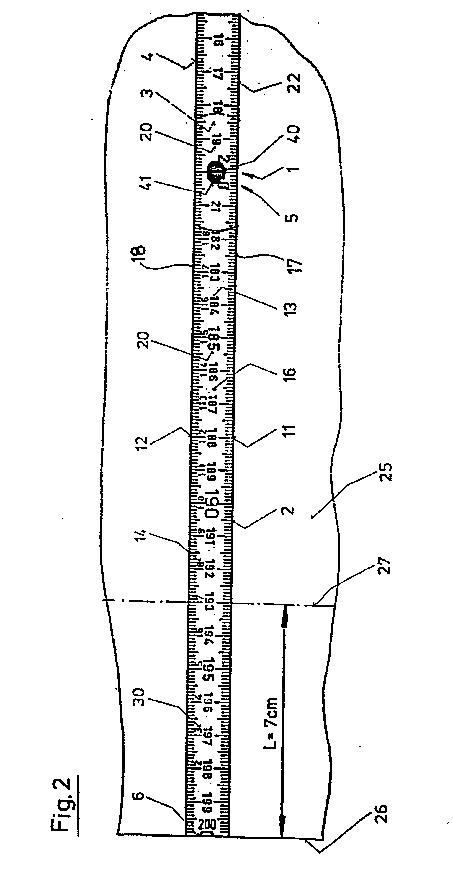
Description
Die vorliegende Erfindung betrifft einen Gliedermasstab, mit hintereinander gekoppelten Klappschenkeln, mit ersten Skalen, von welchen je eine auf einer Seite der Klappschenkel ausgeführt ist, wobei die jeweilige Skala einen Satz von an einer der Masstabkanten angrenzenden Strichen und einen Satz von den Strichen zugeordneten Symbolen umfasst, und mit einer zweiten Skala, welche einer der ersten Skalen zugeordnet ist, wobei die Symbole bzw. Ziffern dieser einander zugeordneten Skalen gegenläufig steigende Reihen bilden und zueinander spiegelbildlich angeordnet sind.The present invention relates to a folding rule, with hinged legs coupled one behind the other, with first scales, one of which is implemented on one side of the hinged legs, the respective scale comprising a set of lines adjacent to one of the scale edges and a set of symbols assigned to the lines , and with a second scale, which is assigned to one of the first scales, the symbols or numbers of these scales assigned to one another forming oppositely increasing rows and being arranged in mirror image to one another.
Es gibt Situationen bei der Anwendung eines solchen Gliedermasstabes, in welchen Längen abgemessen werden müssen, die innerhalb der Länge eines Klappschenkels, d.h. beispielsweise innerhalb eines Bereiches von etwa 20 Zentimetern, liegen. In solchen Situationen müsste nur der erste Klappschenkel vom Paket weggeschwenkt werden und dieser End-Klappschenkel müsste dann an den zu messenden Gegenstand angelegt werden. Wenn die Abmessungen des Gegenstandes jedoch beträthtlich sind, was meistens dann der Fall ist, wenn beispielsweise mit Holz gearbeitet wird, dann liegt die Unterseite des übrigen Teiles des Paketes auf dem zu messenden Gegenstand auf. Wegen der angegebenen Höhe des Paketes befindet sich der weggeschwenkte End-Klappschenkel in einem beträthtlichen Abstand von der Oberfläche des Gegenstandes. Dieser Abstand kann beispielsweise 30mm betragen. Die Abmessung der gewünschten Länge auf dem Gegenstand mit Hilfe des so weit liegenden End-Klappschenkels wäre recht ungenau.There are situations when using such a folding rule, in which lengths must be measured which are within the length of a folding leg, ie for example within a range of about 20 centimeters. In such situations, only the first folding leg would have to be pivoted away from the package and this end folding leg would then have to be placed on the object to be measured. However, if the dimensions of the object are substantial, which is usually the case when working with wood, for example, then the underside of the remaining part of the package rests on the object to be measured. Because of the specified The height of the package is the swung-away end flap at a considerable distance from the surface of the object. This distance can be 30 mm, for example. The dimension of the desired length on the object with the help of the end folding leg lying so far would be quite imprecise.
Um genau messen zu können, schwenkt man normalerweise zumindest noch den zweiten oder sogar noch weitere Mittel-Klappschenkel vom Paket weg und bildet aus diesen eine gerade verlaufende Kette, damit das Paket aus den restlichen Klappschenkeln ausserhalb der Oberfläche des Gegenstandes liegt und damit die Schenkelkette dann auf den Gegenstand flach gelegt werden kann. Diese Handgriffe nehmen jedoch Zeit in Anspruch und wenn man es eilig hat, dann kann einer der Klappschenkel hierbei gebrochen werden. Ausserdem wird der Masstab durch das Entfalten mehrerer Klappschenkel lang und daher unhandlich, usw.In order to be able to measure precisely, you usually swivel at least the second or even further middle folding leg away from the package and form a straight chain from it so that the package from the remaining folding legs lies outside the surface of the object and thus the leg chain can be laid flat on the object. However, these handles take time and if you are in a hurry, one of the folding legs can be broken. In addition, the unfolding of several folding legs makes the scale long and therefore unwieldy, etc.
Die Aufgabe der vorliegenden Erfindung ist, einen Gliedermasstab anzugeben, bei welchem die genannten und noch weitere Nachteile nicht vorkommen.The object of the present invention is to provide a folding rule in which the mentioned and other disadvantages do not occur.
Diese Aufgabe wird beim Gliedermasstab der eingangs genannten Gattung erfindungsgemäss so gelöst, wie dies im kennzeichnenden Teil des Anspruchs 1 definiert ist.This object is achieved according to the invention in the articulated scale of the type mentioned at the outset, as defined in the characterizing part of
Nathstehend werden Ausführungsformen der vorliegenden Erfindung anhand der beiliegenden Zeichnung näher erläutert. Es zeigt:
- Fig. 1 in Draufsicht einen Ausschnitt aus einem Gliedermasstab, welcher zum Stand der Technik gehört,
- Fig. 2 in Draufsicht eine Seite eines der Endabschnitte des vorliegenden Gliedermasstabes, welcher auf einem Gegenstand angelegt ist,
- Fig. 3 in Draufsicht einen Ausschnitt aus einer weiteren Ausführungsform des vorliegenden Masstabes, bei dem sich die Symbole der Zusatzskala unterhalb der Symbole der Hauptskala befinden,
- Fig. 4 perspektivisch die Abmessung einer Strecke auf einem Gegenstand mit Hilfe des Gliedermasstabes gemäss dem Stand der Tethnik und
- Fig. 5 perspektivisth die Abmessung einer Strecke auf dem Gegenstand gemäss Fig. 4 mit Hilfe des vorliegenden Gliedermasstabes.
- 1 is a plan view of a section of a folding rule, which belongs to the prior art,
- 2 is a plan view of one side of one of the end sections of the present folding rule, which is placed on an object,
- 3 is a plan view of a detail from a further embodiment of the present scale, in which the symbols of the additional scale are located below the symbols of the main scale,
- Fig. 4 perspective the dimension of a distance on an object with the help of the folding rule according to the state of the art and
- 5 perspective is the dimension of a distance on the object according to FIG. 4 with the aid of the present folding rule.
Die vorliegende Erfindung betrifft einen Gliedermasstab, dessen Körper Klappschenkel umfasst. Fig. 1 in den beiliegenden Zeichnungen zeigt in Draufsicht einen der Endabschnitte eines vorbekannten Gliedermasstabes, welcher in der US-PS 1 327 691 offenbart ist. Die Klappschenkel des Gliedermasstabes sind als Streifen aus einem steifen Material, z.B. aus Holz, ausgeführt und sie stellen einen wesentlichen Teil des Körpers 1 des Gliedermasstabes dar. Im zusammengefalteten bzw. zusammengelegten Zustand bilden die Klappschenkel ein Paket 1, in dem sie auf-bzw. übereinander liegen. Bei der Darstellung gemäss Fig. 1 ist der im Paket zuoberst liegende Klappschenkel 2 vom Paket 1 weggeklappt und mit dem übrigen Teil des Paketes 1 in Ausrichtung gebracht worden. Dieser Klappschenkel 2 ragt somit vom Paket 1 seitlich weg.The present invention relates to a folding rule, the body of which comprises folding legs. Figure 1 in the accompanying drawings shows a top view of one of the end portions of a prior art link rule disclosed in US Patent 1,327,691. The folding legs of the folding rule are designed as strips made of a rigid material, such as wood and they represent an essential part of the
Die in Fig. 1 rechts liegende Endpartie 3 des genannten Klappschenkels 2 überlappt die Endpartie 3 eines weiteren Klappschenkels 4 und die Klappschenkel 2 und 4 sind im Bereich deren Endpartien 3 mit Hilfe eines Gelenkes 5 miteinander schwenkbar verbunden. Der weitere bzw. zweite Klappschenkel 4 kann auch als einer der Mittel-Klappschenkel bezeichnet werden, weil er beiderends mit Hilfe eines Gelenkes 5 mit benachbarten Klappschenkel gekoppelt ist. Der erst genannte Klappschenkel 2 kann auch als End-Klappschenkel bezeichnet werden, weil er sich am Ende einer Kette 1 aus Klappschenkeln befindet. Die freie Endpartie 7 des End-Klappschenkels 2 ist mit einer Stirnkante 6 abgeschlossen.The
Der genannte weitere Klappschenkel 4 ist der nun im Paket zuoberst liegende Klappschenkel. Die übrigen Klappschenkel dieses Paketes liegen unter diesem Mittel-Klappschenkel 4 und deswegen sind sie in Fig. 1 nicht sichtbar. Zuunterst im Paket befindet sich ein weiterer End-Klappschenkel, welcher praktisch gleich ausgeführt ist wie der in Fig. 1 dargestellte End-Klappschenkel 2. Ein Abschnitt dieses zweiten End-Klappschenkels 22 ist auch in Fig. 2 dargestellt. Fig. 2 zeigt nicht nur die erste Ausführungsform der vorliegenden Erfindung, sondern sie dient auch dazu, die wesentlichen Bestandteile des in Fig. 1 dargestellten Masstabes zu zeigen, welche diesen zwei Masstäben gemeinsam sind.The
Wie bereits erwähnt worden ist, sind die Klappschenkel 2, 4 und 22 als flache Streifen ausgeführt. Folglich weist der jeweilige Klappschenkel zwei flächenhafte Seiten 15 (Fig. 1) und 16 (Fig. 2) auf. Zwischen diesen flächenhaften Seiten 15 und 16 erstrecken sich Schmalseiten 17 und 18 des jeweiligen Klappschenkels 2, 4 bzw. 22.As has already been mentioned, the
Jede Seite des Masstabkörpers 1, d.h. jede der flächenhaften Seiten 15 bzw. 16 der Klappschenkel 2, 4 und 22, ist mit einer Skala 10 (Fig. 1) bzw. 20 (Fig. 2) versehen, wobei diese zwei Skalen 10 und 20 sich von einem Ende der Schenkelkette 1 bis zum anderen Ende derselben erstrecken. Diese Skalen 10 und 20 werden im Nachstehenden auch als erste Skalen oder Hauptskalen bezeichnet. Wenn der Gliedermasstab ein Metermass ist, dann sind diese Skalen 10 und 20 Meterskalen.Each side of the
Die Hauptskalen 10 und 20 sind derart ausgeführt, dass sie zueinander in entgegengesetzten Richtungen verlaufen. Dies bedeutet, dass sich die Nullmarke der oben liegenden und zur Messung normalerweise verwendete Hauptskala 10 links befindet und mit der in Fig. 1 dargestellten Stirnkante 6 im Endbereich 7 des End-Klappschenkels 2 zusammenfällt. Die Nullmarke der anderen und unten liegenden Hauptskala 20 (Fig. 2) befindet sich dagegen rechts, und zwar im Bereich der rechts liegenden Stirnkante 6 (Fig. 1) Dieses Ende der Kette 1 ist in der Fig. 2 nicht dargestellt. Die Endmarke der Vorwärts-Hauptskala 10 (Fig. 1) befindet sich rechts und sie fällt mit der Stirnkante 6 am rechts liegenden End-Klappschenkel 22 zusammen. Die Endmarke der gegenläufigen Hauptskala 20 liegt links und sie fällt mit der links liegenden Stirnkante 6 des End-Klappschenkels 2 zusammen.The
Die jeweilige Hauptskala 10 bzw. 20 umfasst eine Reihe bzw. einen Satz von Teilungsstrichen 12 sowie eine Reihe diesen zugeordneter Symbole 13. Diese Symbole 13 sind den einzelnen Positionen am Strichsatz 12 zugeordnet und sie sind bei einem Metermass Ziffern. Jeder Strichsatz 12 ist auf einer der Seiten 15 und 16 ausgeftragen und der jeweilige Strichsatz 12 ist in jenem Bereich der jeweiligen Seite 15 bzw. 16 angeordnet, welcher an einer der Seitenkanten 17 bzw. 18 des bzw. der Klappschenkel 2, 4 und 22 angrenzt. Der jeweilige Strichsatz 12 ist den Fusspartien der Symbole 13 der jeweiligen Skala 10 bzw. 20 zugeordnet. Damit die Ablesung der Messwerte bequem und rasch vor sich gehen kann, sind die Symbole 13 derart orientiert, dass sie bei der vorwärts laufenden Skala, bei welcher sich die Nullmarke 6 am linken Ende des Gliedermasstabes befindet, aufrecht stehen.The respective
Wenn man den Masstabkörper 1 um die Längsachse desselben um 180 Grad umdreht (Fig. 2), dann kommt die andere und in Fig. 1 untere Skala 20 des Gliedermasstabes auf der Oberseite des Masstabkörpers 1 zum Vorschein. Da diese zweite Skala 20 zur erst genannten Skala 10 gegenläufig ist, sind die Symbole 13 dieser zweiten Skala 20 umgekehrt, d.h. sie stehen für den Betrachter "auf dem Kopf". Dies ist ein erstes Hindernis für die Ablesung der Messwerte mit Hilfe der gegenläufigen Hauptskala 20. Ein weiteres Hindernis besteht darin, dass die Nummerierung 13 der Teilungen 11 und 12 bei dieser Gegenskala 20 von rechts nach links verläuft, so dass eine Ablesung der Messwerte von dieser Gegenskala 20 nur unter beträthtlichen Sthwierigkeiten möglich ist.If one turns the
Wenn man kurze Strecken L, mit einer Länge beispielsweise von 7cm, auf einem Gegenstand 25 abmessen will, dann könnte man eigentlich nur einen der End-Klappschenkel 2 bzw. 22 zu diesem Zweck vom Paket 1 wegschwenken und am Gegenstand 25 anlegen. Dies deswegen, weil die Länge desselben hierzu ausreichen würde. Wenn der Gegenstand 25 jedoch eine Fläche aufweist, welche grösser ist als beispielsweise 30cm mal 30cm, dann kann der End-Klappschenkel 2 bzw. 22, deren Länge in der Regel kleiner ist als 20cm, wegen dem an den End-Schenkel 2 bzw. 22 angesthlossenen Schenkelpaket nicht auf die Gegenstandsoberfläche flach aufgelegt werden.If you want to measure short distances L, with a length of 7 cm, for example, on an
Um diese störende Auswirkung des Paketes 1 auszuschalten, könnte man den Gliedermasstab um seine Längsachse um 180 Grad umdrehen und den Masstabkörper 1 auf den Gegenstand 25 so legen, dass die Aussenseite 15 des weggeklappten End-Schenkels 2 bzw. 22 sowie die Aussenseite des zweitletzten und beim Wegklappen frei gewordenen Mittel-Klappschenkels 4 auf dem Gegenstand 25 aufliegen. Dieses flache Aufliegen des Gliedermasstabes auf dem Gegenstand 25 ist deswegen möglich, weil das Schenkelpaket hochsteht, d.h. dass es von der Ebene des Zeichnungsblattes absteht. In dieser Lage des Masstabes kommt jedoch die gegenläufige Hauptskala 20 auf der nun sichtbaren Innenseite 16 des End-Klappschenkels 2 bzw. 22 zum Vorschein, von der es sehr umständlich ist, Messwerte abzulesen, wie dies vorstehend dargelegt worden ist.In order to eliminate this disruptive effect of the
Damit die Ablesung bzw. Austragung von Strecken auch in den Fällen schnell und genau durchgeführt werden kann, in welchen die gegenläufige Hauptskala 20 am Gliedermasstab sichtbar wird, ist jene längliche Randpartie der Klappschenkel 2, welche an der gegenüberliegenden Masstabkante 17 angrenzt, mit einem zweiten Satz 11 von Teilungsstrichen versehen. Die Symbole 13 der ersten Skala 10 bzw. 20 liegen zwischen den Strichen der beiden Teilungen 11 und 12. Die Symbole 14 der zweiten Skala 30 befinden sich zwischen einem der Sätze der Teilungsstriche 12 und den Symbolen 13 der ersten Skala 10 bzw. 20.So that the reading or discharge of routes also in the In cases where the opposite
Folglich ist die die gegenläufige Hauptskala 20 tragende Seite bzw. Oberfläche 16 zumindest eines der End-Klappschenkel 2 bzw. 22 mit einer in der vorwärts Richtung, d.h. von links nach rechts, verlaufenden Zusatzskala 30 versehen. Die Unterteilungen der Zusatzskala 30 ist der Unterteilung der gegenläufigen Hauptskala 20 gleich, während die Richtung bzw. der Sinn der Zusatzskala 30 zur Richtung bzw. zum Sinn der gegenläufigen Hauptskala 20 entgegengesetzt ist.Consequently, the side or
In Fig. 2 ist unter anderem die Innenseite 16 des erst genannten End-Klappschenkels 2 sichtbar, welche mit der Zusatzskala 30 versehen ist. An die rechts liegende Endpartie 3 des End-Schenkels 2 schliesst sich in Fig. 2 das Schenkelpaket in der vorstehend genannten Weise an. Ein so orientiertes und angeordnetes Paket stört bei der Messung daher nicht. Der im Paket zuoberst liegende und in Fig. 2 daher sichtbare Klappschenkel ist der zweite und vorstehend bereits erwähnte End-Klappschenkel 22 des Paketes bzw. Masstabkörpers 1.2 shows, among other things, the inside 16 of the first-mentioned
Die Nullmarke der Zusatzskala 30 fällt vorteilhaft mit der Endmarke 6 der gegenläufigen Hauptskala 20 zusammen, welche sich auf derselben Seite 16 des Masstabes wie die Zusatzskala 30 befindet. Die Zusatzskala 30 ist mit der sich an der gegenüberliegenden Seite 15 des Masstabkörpers 1 ausgeführten Vorwärts-Hauptskala 10 somit gleichlaufend.The zero mark of the
Die Zusatzskala 30 erstreckt sich von der genannten End- bzw. Nullmarke 6 zumindest über einen Teil des End-Klappschenkels 2 bzw. 22. Vorteilhaft erstreckt sie sich zumindest über die freie Endpartie 7 des End-Klappschenkels 2 bzw. 22. Die Zusatzskala 30 kann sich jedoch auch über den ganzen End-Klappschenkel 2 bzw. 22 erstrecken, wobei sie dann weiter auch auf den an den End-Klappschenkel 2 bzw. 22 unmittelbar angeschlossenen Mittel-Klappschenkel 4 ausgedehnt werden kann. Die Zusatzskala 30 kann sich jedoch auch über die gesamte Länge des Gleidermasstabes erstrecken. Jeder der Klappschenkel 2, 4 bzw. 22 trägt dabei einen Abschnitt der Zusatzskala 30. Auf jeder Seite 15 bzw. 16 des Masstabkörpers 1 ist eine Zusatzskala 30 angeordnet. Dies bedeutet, dass eine zweite Zusatzskala 30 auf der in Fig. 2 nicht sichtbaren flächenhaften Seite 15 des Masstabkörpers 1 angeordnet ist. Die Nullmarke dieser zweiten Zusatzskala fällt mit der Stirnkante 23 (Fig. 4 bzw. 5) des zweiten End-Klappschenkels 22 zusammen. Diese zweite Zusatzskala 30 ist der ersten Hauptskala 10 zugeordnet und sie würde in Bezug auf diese in entgegengesetzter Richtung, d.h. von rechts nach links verlaufen. Die Symbole 14 der zweiten Zusatzskala 30 würden, wenn sie in Fig. 1 dargestellt wären, zu den Symbolen 13 der Hauptskala 10 spiegelbildlich angeordnet sein.The
Die Zusatzskala 30 weist zumindest einen Satz von Teilungsstrichen 11 sowie die den einzelnen Positionen dieser Teilungsstriche zugeordneten Symbole 14 auf. Diese Symbole 14 sind bei einem Metermasstab Ziffern. Die Symbole 14 sind so ausgeführt, dass sie dem Betrachter als aufrechtstehend erscheinen, wenn die Nullmarke der Zusatzskala 30 während der Messung links vom Betrachter liegt und im dargestellten Beispiel mit der Stirnkante 6 des ersten End-Klappschenkels 2 zusammenfällt.The
Die Teilungsstriche 11 bzw. 12 der Hauptskala 10 bzw. 20 können zugleich auch die Teilungsstriche der Zusatzskala 30 sein. Der bereits genannte Abstand zwischen den Symbolen 13 der Hauptskala 10 bzw. 20 und der Reihe 11 bzw. 12 der Teilungsstriche kann zur Anordnung der Symbole 14 der Zusatzskala 30 ausgenützt werden. Dies ist deswegen möglich, weil die Symbole 14 der Zusatzskala 30 sich wegen der gleichen Teilung bei der Zusatzskala 30 und bei der Hauptskala 10 bzw. 20 an derselben Stelle des Masstabes befinden.The graduation marks 11 and 12 of the
Der jeweilige Satz 11 bzw. 12 von Teilungsstrichen umfasst Zentimeterstriche, Millimeterstriche sowie Teilungsstriche, welche den Abstand von 5mm vom jeweiligen Zentimeterstrich markieren. Die Zentimeterstriche sind die längsten bzw. höthsten Striche der jeweiligen Teilung 11 bzw. 12. Die Millimeterstriche sind die kürzesten Striche der Teilung. Die mittigen Striche, entsprechend dem Abstand von 5mm, weisen eine Länge auf, welche zwischen der Länge der Zentimeter- und Millimeterstriche liegt. Die Millimeterstriche sind somit kürzer als die Zentimeterstriche.The respective set 11 or 12 of graduation marks includes centimeter lines, millimeter lines and graduation lines which mark the distance of 5 mm from the respective centimeter line. The centimeter lines are the longest and highest lines of the
Die Symbole der ersten Skala 10 bzw. 20 und der zweiten Skala 30 sind den Zentimeterstrichen zugeordnet. Die Symbole der ersten Skala 10 bzw. 20 können zwischen den sich gegenüberliegenden Zentimeterstrichen der beiden Strichssätze 11 bzw. 12 angeordnet sein. Diese Symbole befinden sich in einem Abstand von den inneren Enden der Zentimeterstriche. Die Symbole der zweiten Skala 30 sind jenem Abschnitt der Zentimeterstriche seitlich zugeordnet, welcher die Millimeterstriche überragt. In solchen Fällen können die Hauptachsen der Symbole der ersten Skala 10 bzw. 20 und der zweiten Skala 30 praktisch rechtwinklig zur Längsachse des Klappschenkels stehen. Der überragende Abschnitt des Zentimeterstriches befindet sich wenigstens teilweise zwischen zwei benathbarten Stellen eines Symbols der zweiten Skala 30, wenn das Symbol zumindest zweistellig ist. Der überragende Abschnitt des Zentimeterstriches befindet sich wenigstens teilweise neben dem betreffenden Symbol der zweiten Skala 30, wenn das Symbol einstellig ist. Die Symbole 13 befinden sich zwischen den Sätzen 11 und 12 der Teilungsstriche der jeweiligen Hauptskala 10 bzw. 20 und sie sind in einem Abstand von diesen Teilungsstrich-Sätzen angeordnet.The symbols of the
In Fig. 2 ist eine Zusatzskala 30 dargestellt, welche nur einen Satz bzw. eine Reihe von Symbolen 14 aufweist. Diese Symbole 14 befinden sich über den Fusspartien der Symbole 13 der Hauptskala 20. Dies bedeutet, dass die genannten Symbole 14 der Zusatzskala 30 sich zwischen den Fusspartien der Symbole 13 der Hauptskala 10 bzw. 20 und dem darüber liegenden Satz 12 von Teilungsstrichen befinden.FIG. 2 shows an
In Fig. 3 ist eine weitere Ausführungsmöglichkeit des vorliegenden Gliedermasstabes gezeigt, bei welchem die Zusatzskala 30 ebenfalls nur eine Reihe bzw. einen einzigen Satz von Symbolen 24 aufweist. Diese Symbole 24 der Zusatzskala 30 befinden sich allerdings unterhalb der Köpfe der Symbole 13 der Hauptskala 10 bzw. 20. Dies bedeutet, dass die genannten Symbole 24 der Zusatzskala 30 sich zwischen den Kopfpartien der Symbole 13 der Hauptskala 10 bzw. 20 und dem darunter liegenden Satz 11 von Teilungsstrichen befinden. Aus dem Vorstehenden geht hervor, dass die Symbole 24 dieser Zusatzskala 30 in bezug auf die Symbole 13 der Hauptskala 10 bzw. 20 spiegelbildlich angeordnet sind. Es versteht sich, dass die Zusatzskala 30 zugleich die beiden Sätze 14 und 24 der Symbole aufweisen kann. Diese Symbolensätze 14 und 24 können dann so angeordnet sein, wie dies in Fig. 2 und 3 dargestellt ist. Sie können allerdings in unterschiedlicher Weise ausgeführt sein, so dass sie sich voneinander optisch unterscheiden lassen. Die Symbole 13 der Hauptskala 10 bzw. 20 oder/und die Symbole 14 bzw. 24 der Zusatzskala 30 können auch so ausgeführt sein, dass sie eine maschinelle Ablesung bzw. Austragung der jeweiligen Streckenlänge ermöglichen.3 shows a further possible embodiment of the present folding rule, in which the
Zur leichteren optischen Unterscheidung können die Symbole 14 der Zusatzskala 30 anders ausgeführt sein als die Symbole 13 der zugeordneten Hauptskala 10 bzw. 20, welche sich auf derselben Seite 15 bzw. 16 des Masstabkörpers 1 befinden. Die beiden Gruppen von Symbolen 13 und 14 können verschiedenfarbig oder untersthiedlich geformt sein. Aus Platzgründen können die Symbole 14 der Zusatzskala 30 kleiner sein als die Symbole 13 der Hauptskala 10 bzw. 20, was eigentlich ebenfalls zur leichteren optischen Unterscheidung zwischen den beiden Gruppen der Symbole 13 und 14 beitragen kann.For easier visual differentiation, the
Falls die Hauptachse der Symbole 13 der Hauptskala 10 bzw. 20 praktisch senkrecht zur Längsrichtung des jeweiligen Klappschenkels 2, 4 oder 22 verläuft, so kann die Hauptachse der Symbole 14 der Zusatzskala 30 ebenfalls praktisch senkrecht zur Längsrichtung des Klappschenkels verlaufen. Hierbei sind die Symbole 14 der Zusatzskalla 30 zu den Symbolen 13 der sich auf derselben Seite 15 bzw. 16 des Klappschenkels 2, 4 bzw. 22 bzw. des Gliedermasstabes angeordneten Hauptskala 10 bzw. 20 jedoch spiegelbildlich. Es ist auch möglich, die Symbole 13 und 14 so auszuführen, dass die Hauptachse derselben praktisch parallel zur Längsachse des Masstabes verläuft. Dann haben die liegenden Symbolgruppen 13 und 14 eine gegenläufige Orientierung, um die Ablesung in der Vorwärtsrichtung von der Zusatzskala 30 zu ermöglichen.If the main axis of the
Das zwei aufeinander folgende Klappschenkel 2, 4 bzw. 22 verbindende Gelenk 5 umfasst unter anderem einen Bolzen 40 (Fig. 1 und 3), welcher aus einem kompakten Material, beispielsweise aus Kunststoff, ist. An einem Ende dieses Bolzens 40 ist ein im wesentlichen zylinderförmiger Kopf 41 (Fig. 2) angeformt, dessen Durchmesser grösser ist als der Durchmesser des stiftähnlichen Abschnittes 42 des Bolzens 40. Der Bolzenkopf 41 ist in der äusseren Fläche 15 der Endpartie 3 eines der miteinander gekoppelten Klappschenkel 2 eingelassen. Der Stift 42 geht durch die Endpartien 3 der beiden miteinander verbundenen Klappschenkel 2 und 4 hindurch und seine Stirnfläche ist mit der äusseren Oberfläche 16 des anderen Klappschenkels 4 bündig. In diesem Schenkel 4 ist eine Nut 43 ausgeführt, welche in der Längsrichtung dieses Schenkels 4 verläuft. In dieser Längsnut 43 liegt eine Biegefeder 44, welche durch eine in der Endpartie des Bolzenstiftes 42 vorhandene Bohrung (nicht dargestellt) hindurchgeht.The joint 5 connecting two
Der Bolzen 40 ist derart ausgeführt ist, dass er sich von den Klappschenkeln 2, 4 bzw. 22 optisch abhebt. Dies kann beispielsweise dadurch erreicht werden, dass der Bolzen 40 eine andere Farbe hat als die Klappschenkel. Wenn die Klappschenkel beispielsweise gelb sind, dann kann der Bolzen 40 vorteilhaft rot sein. Ein sich von den Klappschenkeln 2 und 4 optisch abhebender Bolzen 40 ist in Fig. 3 dargestellt, wobei von diesem in Fig. 3 allerdings nur die Stirnfläche des Stiftes 42 desselben sichtbar ist. Der Bolzen 40 kann auch so ausgeführt sein, dass der Kopf 41 und der Stift 42 desselben unterschiedliche Farben oder/und Formen aufweisen, so dass die beiden Enden des Bolzens 40 sich voneinander optisch abheben.The
Diese Massnahmen bieten unter anderem den Vorteil, dass die gleich langen Abstände am Gliedermasstab, welche zwischen zwei benachbarten Bolzen 40 liegen, auch aus einer grösseren Entfernung gut sichtbar sind. Diese Massnahme kann auch jenen Personen zugute kommen, welche ein geschwächtes Sehvermögen haben und für welche es vielleicht nur genügt, dass sie im betreffenden Fall eine nur grobe Information über die sie interessierende Strecke erhalten.These measures offer the advantage, among other things, that the equally long distances on the folding rule, which lie between two
Ein Beispiel dafür, wie man mit diesem neuen Gliedermasstab arbeiten kann, lässt sich anhand von Fig. 2 angeben. In Fig. 2 ist nur ein Ausschnitt aus dem Gegenstand 25 gezeigt, weil die Fläche der Oberfläche desselben grösser ist als 30cm mal 30cm. In der Entfernung von 7cm von einer der Kanten 26 des Gegenstandes 25 soll eine Linie 27 parallel zur Gegenstandskante 26 geführt werden. Man schwenkt den End-Klappschenkel 2 vom übrigen Teil des gefalteten Masstabkörpers 1 weg und legt diesen Schenkel 2 mit seiner Aussenseite 15 auf die Oberfläche des Gegenstandes 25. Der Schenkel 2 wird derart angelegt, dass die Stirnkante 6 desselben mit der Gegenstandskante 26 fluchtet. Die Hauptskala 20, welche sich auf der Innenseite 16 des End-Klappschenkels 2 befindet, ist gegenläufig und bei der Abmessung der genannten Strecke von 7cm ist sie somit kaum zu gebrauchen. Da die Innenseite 16 des Klappschenkels 2 jedoch auch mit der Zusatzskala 30 versehen ist, welche von links nach rechts verläuft, kann man die gewünschte Strecke von 7cm mit Hilfe dieser Zusatzskala 30 problemlos festlegen. Danach kann die Linie 27 mit Hilfe weiterer Instrumente gezogen werden.An example of how one can work with this new folding rule can be given with reference to FIG. 2. In Fig. 2 only a section of the
Da die Zusatzskala 30 sich auch zumindest auf dem anderen End-Klappschenkel 22 befindet, könnte man in gleich einfacher Weise auch dann vorgehen, wenn man diesen zweiten End-Klappschenkel 22 zu diesem Zweck zufälligerweise vom Masstabkörper 1 wegklappen würde. Folglich kommt es nicht darauf an, an welcher Seite des Masstabkörpers 1 sich der oder die im jeweiligen Fall verwendeten Klappschenkel 2 oder 22 und bzw. auch 4 befinden.Since the
Ein weiteres beispiel für die Anwendung des vorliegenden Gliedermasstabes ist in Fig. 4 und 5 angegeben. In diesen Fig. 4 und 5 ist ein Endabschnitt eines Gegenstandes 35 dargestellt, welcher einen langen Grundkörper 36 aufweist. An einem Ende dieses Grundkörpers 36 ist eine rechtwinklig dazu stehende Lasche 37 angeordnet. In einem Abstand von 31 cm von dieser Lasche 37 soll eine Nut 38 im Grundkörper 36 senkrecht zur Längsachse dieses ausgeführt werden. Das Problem besteht darin, die Strecke von 31 cm möglichst genau festzulegen. Zur Festlegung dieser Strecke wird in Fig. 4 ein herkömmlicher Gliedermasstab verwendet. Zur Abmessung der genannten Strecke kann man bloss die zwei ersten Klappschenkel 2 und 4 des Gliedermasstabes verwenden. Damit man die genannten Strecke mit Hilfe des bekannten Masstabes möglichst genau abmessen kann, muss man den zweiten Klappschenkel 4 stark nach unten verbiegen, wie dies in Fig. 4 angedeutet ist. Dies ist eine mühsame Angelegenheit und auch wenn man den Schenkel 4 wirklich stark verbiegt, dann gelingt es doch nicht, den Teilungsstrich entsprechend dem Symbol 13 entsprechend der Marke von 31 cm bis auf die Oberfläche des Grundkörpers 36 hinunterzudrücken. Dies deswegen, weil die Höhe des gefalteten Abschnittes des Masstabkörpers 1 verhältnismässig hoch ist und weil das Material der Schenkel 2, 4 bzw. 22 verhältnismässig steif ist.Another example of the application of the present folding rule is given in FIGS. 4 and 5. 4 and 5, an end section of an
In Fig. 5 wird zur Festlegung der genannten Strecke dagegen der vorliegende Masstab verwendet. Man schwenkt bei diesem Masstab den End-Klappschenkel 2 sowie den zweitletzten Schenkel 4 vom übrigen Teil des gefalteten Masstabkörpers 1 weg und legt diese Schenkel 2 und 4 mit ihrer Aussenseite flach auf die Oberfläche des Gegenstandes 35. Die Schenkel 2 und 4 werden auf den Gegenstand 35 derart angelegt, dass die Stirnkante 6 des End-Schenkels 2 an der Innenseite der Lasche 37 anschlägt. Die Hauptskala 20, welche sich auf der Innenseite 16 der Klappschenkel 2 und 4 befindet, ist gegenläufig und bei der Abmessung der genannten Strecke von 31cm ist sie somit kaum zu gebrauchen. Da die Innenseite 16 der Klappschenkel 2 und 4 jedoch auch mit der Zusatzskala 30 versehen ist, welche von links nach rechts verläuft, kann man die gewünschte Strecke von 31cm mit Hilfe dieser Zusatzskala 30 problemlos abmessen. Danach kann die Nut 38 mit Hilfe eines geeigneten Werkzeuges hergestellt werden.In contrast, the present scale is used in FIG. With this scale, the
Claims (10)
Applications Claiming Priority (2)
| Application Number | Priority Date | Filing Date | Title |
|---|---|---|---|
| CH26890A CH681389A5 (en) | 1990-01-29 | 1990-01-29 | |
| CH268/90 | 1990-01-29 |
Publications (3)
| Publication Number | Publication Date |
|---|---|
| EP0448506A2 true EP0448506A2 (en) | 1991-09-25 |
| EP0448506A3 EP0448506A3 (en) | 1991-10-09 |
| EP0448506B1 EP0448506B1 (en) | 1994-08-10 |
Family
ID=4183133
Family Applications (1)
| Application Number | Title | Priority Date | Filing Date |
|---|---|---|---|
| EP19910810067 Expired - Lifetime EP0448506B1 (en) | 1990-01-29 | 1991-01-29 | Folding ruler |
Country Status (3)
| Country | Link |
|---|---|
| EP (1) | EP0448506B1 (en) |
| CH (1) | CH681389A5 (en) |
| DE (2) | DE9001859U1 (en) |
Cited By (2)
| Publication number | Priority date | Publication date | Assignee | Title |
|---|---|---|---|---|
| US7111408B2 (en) | 2005-02-02 | 2006-09-26 | Cooper Brands, Inc. | Folding rule |
| CN112607050A (en) * | 2020-12-24 | 2021-04-06 | 中航贵州飞机有限责任公司 | Rechargeable type luminous measuring scale for measuring level of airplane |
Families Citing this family (1)
| Publication number | Priority date | Publication date | Assignee | Title |
|---|---|---|---|---|
| DE102012202289B4 (en) * | 2011-02-16 | 2026-02-19 | Adga Adolf Gampper Gmbh | Folding ruler with double scale |
Family Cites Families (6)
| Publication number | Priority date | Publication date | Assignee | Title |
|---|---|---|---|---|
| US1372691A (en) * | 1921-03-29 | Charles hebbman | ||
| US1469944A (en) * | 1922-05-01 | 1923-10-09 | Moses C Merrill | Measuring rule |
| CH186307A (en) * | 1936-02-04 | 1936-09-15 | Wenger Heinrich | Collapsible folding rule. |
| US2555741A (en) * | 1950-06-23 | 1951-06-05 | Greene Oscar | Collapsible measuring rule |
| DE852154C (en) * | 1950-10-17 | 1952-10-13 | Heinz Grundmann | Folding rule with additional equipment for internal measurements |
| FR2517425A1 (en) * | 1981-11-30 | 1983-06-03 | Ronayette Pierre | Rigid folding metre rule construction - has riveted portions of which ends have V=grooves cut to provide easy alignment with central axis of rule |
-
1990
- 1990-01-29 CH CH26890A patent/CH681389A5/de not_active IP Right Cessation
- 1990-02-16 DE DE9001859U patent/DE9001859U1/en not_active Expired - Lifetime
-
1991
- 1991-01-29 DE DE59102463T patent/DE59102463D1/en not_active Expired - Lifetime
- 1991-01-29 EP EP19910810067 patent/EP0448506B1/en not_active Expired - Lifetime
Cited By (2)
| Publication number | Priority date | Publication date | Assignee | Title |
|---|---|---|---|---|
| US7111408B2 (en) | 2005-02-02 | 2006-09-26 | Cooper Brands, Inc. | Folding rule |
| CN112607050A (en) * | 2020-12-24 | 2021-04-06 | 中航贵州飞机有限责任公司 | Rechargeable type luminous measuring scale for measuring level of airplane |
Also Published As
| Publication number | Publication date |
|---|---|
| DE59102463D1 (en) | 1994-09-15 |
| CH681389A5 (en) | 1993-03-15 |
| EP0448506B1 (en) | 1994-08-10 |
| DE9001859U1 (en) | 1991-06-06 |
| EP0448506A3 (en) | 1991-10-09 |
Similar Documents
| Publication | Publication Date | Title |
|---|---|---|
| DE69402946T2 (en) | Device for measuring and marking | |
| DE69418628T2 (en) | COMBINATION SCALE WITH SEGMENTED INTERLOCKING ELEMENTS | |
| DE2918321C2 (en) | Pitch and parallel drawing angles | |
| DE20111665U1 (en) | Angle measuring device with additional ruler | |
| DE2905015A1 (en) | DRAWING DEVICE | |
| DE3739823C1 (en) | Protractor | |
| DE102021133883A1 (en) | marking tool | |
| EP0448506B1 (en) | Folding ruler | |
| DE3117889A1 (en) | METHOD AND DEVICE FOR ADJUSTING A DENTAL ARTICULATOR | |
| AT506504B1 (en) | SECTIONAL SCALE | |
| DE102012202289B4 (en) | Folding ruler with double scale | |
| DE3630616C2 (en) | ||
| DE102020003115A1 (en) | Folding rule as a multi-purpose device | |
| DE102024110037B4 (en) | Device for measuring and drawing | |
| DE3632751C1 (en) | Length measuring probe with a pivoting probe arm | |
| DE3430378A1 (en) | DRAWING DEVICE | |
| DE2701097A1 (en) | DEVICE FOR REPRESENTING AN OBJECTIVE IN ACCURATE CENTRAL PERSPECTIVE | |
| DE19603006A1 (en) | Device for measuring and displaying angles | |
| DE100464C (en) | ||
| DE4223747B4 (en) | folding rule | |
| DE4336502A1 (en) | Device for applying a plurality of markings aligned with respect to the horizontal | |
| DE3415340A1 (en) | DEVICE FOR MEASURING AND CALCULATING KNITWEAR | |
| DE907751C (en) | Drawing triangle with protractor | |
| DE751487C (en) | Easel file | |
| DE3527072C2 (en) |
Legal Events
| Date | Code | Title | Description |
|---|---|---|---|
| PUAI | Public reference made under article 153(3) epc to a published international application that has entered the european phase |
Free format text: ORIGINAL CODE: 0009012 |
|
| PUAL | Search report despatched |
Free format text: ORIGINAL CODE: 0009013 |
|
| AK | Designated contracting states |
Kind code of ref document: A2 Designated state(s): BE DE FR IT SE |
|
| AK | Designated contracting states |
Kind code of ref document: A3 Designated state(s): BE DE FR IT SE |
|
| 17P | Request for examination filed |
Effective date: 19920318 |
|
| 17Q | First examination report despatched |
Effective date: 19930528 |
|
| GRAA | (expected) grant |
Free format text: ORIGINAL CODE: 0009210 |
|
| AK | Designated contracting states |
Kind code of ref document: B1 Designated state(s): BE DE FR IT SE |
|
| REF | Corresponds to: |
Ref document number: 59102463 Country of ref document: DE Date of ref document: 19940915 |
|
| ITF | It: translation for a ep patent filed | ||
| PG25 | Lapsed in a contracting state [announced via postgrant information from national office to epo] |
Ref country code: SE Effective date: 19941110 |
|
| ET | Fr: translation filed | ||
| PLBE | No opposition filed within time limit |
Free format text: ORIGINAL CODE: 0009261 |
|
| 26N | No opposition filed | ||
| PGFP | Annual fee paid to national office [announced via postgrant information from national office to epo] |
Ref country code: FR Payment date: 19960110 Year of fee payment: 6 |
|
| PGFP | Annual fee paid to national office [announced via postgrant information from national office to epo] |
Ref country code: BE Payment date: 19960126 Year of fee payment: 6 |
|
| PG25 | Lapsed in a contracting state [announced via postgrant information from national office to epo] |
Ref country code: BE Effective date: 19970131 |
|
| BERE | Be: lapsed |
Owner name: ETS SINOVAL Effective date: 19970131 |
|
| PG25 | Lapsed in a contracting state [announced via postgrant information from national office to epo] |
Ref country code: FR Effective date: 19970930 |
|
| REG | Reference to a national code |
Ref country code: FR Ref legal event code: ST |
|
| PGFP | Annual fee paid to national office [announced via postgrant information from national office to epo] |
Ref country code: IT Payment date: 20100127 Year of fee payment: 20 |
|
| PGFP | Annual fee paid to national office [announced via postgrant information from national office to epo] |
Ref country code: DE Payment date: 20100131 Year of fee payment: 20 |
|
| PG25 | Lapsed in a contracting state [announced via postgrant information from national office to epo] |
Ref country code: DE Free format text: LAPSE BECAUSE OF EXPIRATION OF PROTECTION Effective date: 20110129 |