EP0448506A2 - Mètre pliant - Google Patents
Mètre pliant Download PDFInfo
- Publication number
- EP0448506A2 EP0448506A2 EP91810067A EP91810067A EP0448506A2 EP 0448506 A2 EP0448506 A2 EP 0448506A2 EP 91810067 A EP91810067 A EP 91810067A EP 91810067 A EP91810067 A EP 91810067A EP 0448506 A2 EP0448506 A2 EP 0448506A2
- Authority
- EP
- European Patent Office
- Prior art keywords
- scale
- symbols
- folding
- lines
- legs
- Prior art date
- Legal status (The legal status is an assumption and is not a legal conclusion. Google has not performed a legal analysis and makes no representation as to the accuracy of the status listed.)
- Granted
Links
Images


Classifications
-
- G—PHYSICS
- G01—MEASURING; TESTING
- G01B—MEASURING LENGTH, THICKNESS OR SIMILAR LINEAR DIMENSIONS; MEASURING ANGLES; MEASURING AREAS; MEASURING IRREGULARITIES OF SURFACES OR CONTOURS
- G01B3/00—Measuring instruments characterised by the use of mechanical techniques
- G01B3/02—Rulers with scales or marks for direct reading
- G01B3/04—Rulers with scales or marks for direct reading rigid
- G01B3/06—Rulers with scales or marks for direct reading rigid folding
Definitions
- the present invention relates to a folding rule, with hinged legs coupled one behind the other, with first scales, one of which is implemented on one side of the hinged legs, the respective scale comprising a set of lines adjacent to one of the scale edges and a set of symbols assigned to the lines , and with a second scale, which is assigned to one of the first scales, the symbols or numbers of these scales assigned to one another forming oppositely increasing rows and being arranged in mirror image to one another.
- the object of the present invention is to provide a folding rule in which the mentioned and other disadvantages do not occur.
- the present invention relates to a folding rule, the body of which comprises folding legs.
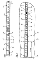
- Figure 1 in the accompanying drawings shows a top view of one of the end portions of a prior art link rule disclosed in US Patent 1,327,691.
- the folding legs of the folding rule are designed as strips made of a rigid material, such as wood and they represent an essential part of the body 1 of the folding rule.
- the folding legs In the folded or collapsed state, the folding legs form a package 1 in which they can be opened or closed. lie on top of each other.
- the flap leg 2 located at the top of the package has been folded away from the package 1 and brought into alignment with the rest of the package 1. This folding leg 2 thus protrudes laterally away from the package 1.
- the end portion 3 of the folding leg 2 on the right in FIG. 1 overlaps the end portion 3 of a further folding leg 4 and the folding legs 2 and 4 are pivotally connected to one another in the region of their end portions 3 by means of a joint 5.
- the further or second folding leg 4 can also be referred to as one of the middle folding legs, because it is coupled at both ends with the aid of a joint 5 to adjacent folding legs.
- the first-mentioned folding arm 2 can also be referred to as an end-folding arm because it is located at the end of a chain 1 made of folding arms.
- the free end portion 7 of the end folding leg 2 is closed with an end edge 6.
- Fig. 2 not only shows the first embodiment of the present invention, but also serves to show the essential components of the scale shown in Fig. 1, which are common to these two scales.
- the folding legs 2, 4 and 22 are designed as flat strips. Consequently, the respective folding leg has two flat sides 15 (FIG. 1) and 16 (FIG. 2). Narrow sides 17 and 18 of the respective folding leg 2, 4 and 22 respectively extend between these planar sides 15 and 16.
- These scales 10 and 20 are also referred to below as first scales or main scales. If the folding rule is a meter scale, then these scales are 10 and 20 meter scales.
- the main scales 10 and 20 are designed such that they run in opposite directions to one another. This means that the zero mark of the main scale 10 located above and normally used for the measurement is on the left and coincides with the end edge 6 shown in FIG. 1 in the end region 7 of the end folding leg 2.
- the zero mark of the other and lower main scale 20 (FIG. 2), on the other hand, is on the right, in the area of the right end edge 6 (FIG. 1). This end of the chain 1 is not shown in FIG. 2.
- the end mark of the forward main scale 10 (FIG. 1) is on the right and it coincides with the front edge 6 on the right end flap leg 22.
- the end mark of the opposing main scale 20 is on the left and it coincides with the left end edge 6 of the end flap leg 2.
- the respective main scale 10 or 20 comprises a row or a set of division lines 12 and a row of symbols 13 assigned to them. These symbols 13 are assigned to the individual positions on the stroke set 12 and are numerals in a meter measure. Each stroke set 12 is carried out on one of the sides 15 and 16 and the respective stroke set 12 is arranged in that region of the respective side 15 or 16 which is on one of the side edges 17 or 18 of the or the Folding legs 2, 4 and 22 are adjacent.
- the respective stroke set 12 is assigned to the base parts of the symbols 13 of the respective scale 10 or 20. So that the reading of the measured values can be carried out conveniently and quickly, the symbols 13 are oriented in such a way that they stand upright on the forward-running scale, on which the zero mark 6 is located at the left end of the folding rule.
- That elongated edge part of the folding legs 2 which adjoins the opposite scale edge 17 is provided with a second set 11 of division marks.
- the symbols 13 of the first scale 10 and 20 lie between the lines of the two divisions 11 and 12.
- the symbols 14 of the second scale 30 are located between one of the sets of the division lines 12 and the symbols 13 of the first scale 10 and 20.
- the side or surface 16 carrying the opposing main scale 20 is at least one of the end folding legs 2 or 22 with one in the forward direction, i.e. from left to right, provided additional scale 30.
- the subdivisions of the additional scale 30 are the same as the subdivisions of the opposite main scale 20, while the direction or sense of the additional scale 30 is opposite to the direction or sense of the opposite main scale 20.
- FIG. 2 shows, among other things, the inside 16 of the first-mentioned folding leg 2, which is provided with the additional scale 30.
- the bundle of legs adjoins the end part 3 of the end leg 2 on the right in the manner mentioned above.
- a package that is oriented and arranged in this way does not interfere with the measurement.
- the one in the package The uppermost folding arm, which is therefore visible in FIG. 2, is the second and already mentioned end folding arm 22 of the package or scale body 1.
- the zero mark of the additional scale 30 advantageously coincides with the end mark 6 of the opposite main scale 20, which is located on the same side 16 of the scale as the additional scale 30.
- the additional scale 30 is thus synchronized with the forward main scale 10 on the opposite side 15 of the scale body 1.
- the additional scale 30 extends from the end or zero mark 6 mentioned at least over part of the end folding leg 2 or 22. Advantageously, it extends at least over the free end part 7 of the end folding leg 2 or 22.
- the additional scale 30 can however, they also extend over the entire end flap leg 2 or 22, in which case it can then be extended further to the middle flap leg 4 directly connected to the end flap leg 2 or 22.
- the additional scale 30 can, however, also extend over the entire length of the clothing scale.
- Each of the folding legs 2, 4 and 22 carries a section of the additional scale 30.
- An additional scale 30 is arranged on each side 15 and 16 of the scale body 1. This means that a second additional scale 30 on the flat side 15 of the surface that is not visible in FIG. 2 Scale body 1 is arranged.
- this second additional scale 30 is assigned to the first main scale 10 and it would run in the opposite direction with respect to this, ie from right to left.
- the additional scale 30 has at least one set of division lines 11 and the symbols 14 assigned to the individual positions of these division lines. On a meter scale, these symbols 14 are numbers. The symbols 14 are designed in such a way that they appear to the observer as upright when the zero mark of the additional scale 30 lies to the left of the observer during the measurement and coincides with the end edge 6 of the first end folding leg 2 in the example shown.
- the graduation marks 11 and 12 of the main scale 10 and 20 can also be the graduation marks of the additional scale 30.
- the already mentioned distance between the symbols 13 of the main scale 10 or 20 and the row 11 or 12 of the division lines can be used to arrange the symbols 14 of the additional scale 30. This is possible because the symbols 14 of the additional scale 30 differ due to the same division in the additional scale 30 and on the main scale 10 or 20 are in the same place on the scale.
- the respective set 11 or 12 of graduation marks includes centimeter lines, millimeter lines and graduation lines which mark the distance of 5 mm from the respective centimeter line.
- the centimeter lines are the longest and highest lines of the respective division 11 and 12.
- the millimeter lines are the shortest lines of the division.
- the central lines, corresponding to the distance of 5mm, have a length that lies between the length of the centimeter and millimeter lines. The millimeter lines are therefore shorter than the centimeter lines.
- the symbols of the first scale 10 or 20 and the second scale 30 are assigned to the centimeter lines.
- the symbols of the first scale 10 or 20 can be arranged between the opposing centimeter lines of the two line sets 11 or 12. These symbols are spaced from the inner ends of the centimeter lines.
- the symbols of the second scale 30 are laterally assigned to that section of the centimeter lines that projects above the millimeter lines. In such cases, the main axes of the symbols of the first scale 10 or 20 and the second scale 30 can be practically perpendicular to the longitudinal axis of the folding leg.
- the outstanding one The section of the centimeter line is located at least partially between two locations of a symbol on the second scale 30, if the symbol has at least two digits.
- the protruding section of the centimeter line is at least partially next to the relevant symbol of the second scale 30 if the symbol is a single digit.
- the symbols 13 are located between the sets 11 and 12 of the division lines of the respective main scale 10 and 20 and they are arranged at a distance from these division line sets.
- FIG. 2 shows an additional scale 30 which has only one set or a series of symbols 14. These symbols 14 are located above the base parts of the symbols 13 of the main scale 20. This means that the mentioned symbols 14 of the additional scale 30 are located between the base parts of the symbols 13 of the main scale 10 and 20 and the set 12 of division marks above them.
- the additional scale 30 likewise has only one row or a single set of symbols 24.
- these symbols 24 of the additional scale 30 are located below the heads of the symbols 13 of the main scale 10 or 20.
- the symbols 24 of the additional scale 30 mentioned are located between the head portions of the symbols 13 of the Main scale 10 or 20 and the underlying set 11 of graduation marks. From the above it can be seen that the symbols 24 of this additional scale 30 are arranged in mirror image with respect to the symbols 13 of the main scale 10 or 20.
- the additional scale 30 can also have the two sets 14 and 24 of the symbols. These symbol sets 14 and 24 can then be arranged as shown in FIGS. 2 and 3.
- the symbols 13 of the main scale 10 or 20 or / and the symbols 14 or 24 of the additional scale 30 can also be designed in such a way that they enable automatic reading or discharge of the respective route length.
- the symbols 14 of the additional scale 30 can be designed differently than the symbols 13 of the assigned main scale 10 or 20, which are located on the same side 15 or 16 of the scale body 1.
- the two groups of symbols 13 and 14 can be of different colors or different shapes.
- the symbols 14 of the additional scale 30 can be smaller than the symbols 13 of the main scale 10 or 20, which can actually also contribute to an easier visual distinction between the two groups of symbols 13 and 14.
- the main axis of the symbols 13 of the main scale 10 or 20 runs practically perpendicular to the longitudinal direction of the respective folding leg 2, 4 or 22, the main axis of the symbols 14 of the additional scale 30 can likewise run practically perpendicular to the longitudinal direction of the folding leg.
- the symbols 14 of the additional scale 30 are a mirror image of the symbols 13 of the main scale 10 or 20 arranged on the same side 15 or 16 of the folding leg 2, 4 or 22 or of the folding rule. It is also possible to design the symbols 13 and 14 in such a way that the main axis thereof runs practically parallel to the longitudinal axis of the scale. Then the lying symbol groups 13 and 14 have an opposite orientation in order to enable the reading in the forward direction from the additional scale 30.
- the joint 5 connecting two successive folding legs 2, 4 and 22 comprises, among other things, a bolt 40 (FIGS. 1 and 3), which is made of a compact material, for example made of plastic.
- An essentially cylindrical head 41 (FIG. 2), the diameter of which is larger than the diameter of the pin-like section 42 of the bolt 40, is formed on one end of this bolt 40.
- the bolt head 41 is one of the two in the outer surface 15 of the end part 3 coupled folding leg 2 embedded.
- the pin 42 goes through the end parts 3 of the two hinged legs 2 and 4 connected to one another and its end face is flush with the outer surface 16 of the other hinged leg 4.
- this leg 4 there is a groove 43 which runs in the longitudinal direction of this leg 4.
- a spiral spring 44 which passes through a hole (not shown) in the end part of the pin 42.
- the bolt 40 is designed such that it stands out visually from the flap legs 2, 4 and 22. This can be achieved, for example, in that the bolt 40 has a different color than the folding legs. If the folding legs are yellow, for example, then the bolt 40 can advantageously be red.
- a bolt 40, which stands out optically from the hinged legs 2 and 4, is shown in FIG. 3, only the end face of the pin 42 of the same being visible in FIG. 3.
- the bolt 40 can also be designed such that the head 41 and the pin 42 of the same have different colors or / and shapes, so that the two ends of the bolt 40 stand out visually.
- FIG. 2 An example of how one can work with this new folding rule can be given with reference to FIG. 2.
- Fig. 2 only a section of the object 25 is shown because the surface area of the same is larger than 30 cm by 30 cm.
- a line 27 is to be guided parallel to the object edge 26.
- the end folding leg 2 is pivoted away from the remaining part of the folded scale body 1 and this leg 2 is placed with its outer side 15 on the surface of the object 25.
- the leg 2 is placed in such a way that the end edge 6 thereof is aligned with the object edge 26.
- the main scale 20, which is located on the inside 16 of the end flap leg 2 runs in opposite directions and is therefore hardly usable given the dimension of the above-mentioned distance of 7 cm.
- the inside 16 of the folding leg 2 is also provided with the additional scale 30, which runs from left to right, the desired distance of 7 cm can easily be determined using this additional scale 30.
- line 27 can be drawn using other instruments.
- the additional scale 30 is also at least on the other end folding leg 22, one could proceed in a similarly simple manner if one would accidentally fold away the second end folding leg 22 from the scale body 1 for this purpose. Consequently, it is not important on which side of the scale body 1 the one or more folding legs 2 or 22 and / or 4 used in the respective case are located.
- FIGS. 4 and 5 Another example of the application of the present folding rule is given in FIGS. 4 and 5.
- an end section of an object 35 is shown, which has a long base body 36. At one end of this base body 36 there is a tab 37 at right angles thereto. At a distance of 31 cm from this tab 37, a groove 38 is to be made in the base body 36 perpendicular to the longitudinal axis thereof.
- the problem is to determine the 31 cm distance as precisely as possible.
- a conventional folding rule is used in FIG. 4 to determine this distance.
- the present scale is used in FIG.
- the end folding leg 2 and the second last leg 4 are pivoted away from the remaining part of the folded scale body 1 and these legs 2 and 4 are placed flat on the outside of the surface of the object 35.
- the legs 2 and 4 become on the object 35 created such that the end edge 6 of the end leg 2 strikes the inside of the tab 37.
- the main scale 20, which is located on the inside 16 of the hinged legs 2 and 4 runs in opposite directions and is therefore hardly usable given the dimension of the stated distance of 31 cm.
- the inside 16 of the folding legs 2 and 4 is also provided with the additional scale 30, which runs from left to right, the desired distance of 31 cm can be easily measured using this additional scale 30.
- the groove 38 can then be produced using a suitable tool.
Landscapes
- Physics & Mathematics (AREA)
- General Physics & Mathematics (AREA)
- Length-Measuring Instruments Using Mechanical Means (AREA)
Applications Claiming Priority (2)
| Application Number | Priority Date | Filing Date | Title |
|---|---|---|---|
| CH268/90 | 1990-01-29 | ||
| CH26890A CH681389A5 (fr) | 1990-01-29 | 1990-01-29 |
Publications (3)
| Publication Number | Publication Date |
|---|---|
| EP0448506A2 true EP0448506A2 (fr) | 1991-09-25 |
| EP0448506A3 EP0448506A3 (fr) | 1991-10-09 |
| EP0448506B1 EP0448506B1 (fr) | 1994-08-10 |
Family
ID=4183133
Family Applications (1)
| Application Number | Title | Priority Date | Filing Date |
|---|---|---|---|
| EP19910810067 Expired - Lifetime EP0448506B1 (fr) | 1990-01-29 | 1991-01-29 | Mètre pliant |
Country Status (3)
| Country | Link |
|---|---|
| EP (1) | EP0448506B1 (fr) |
| CH (1) | CH681389A5 (fr) |
| DE (2) | DE9001859U1 (fr) |
Cited By (2)
| Publication number | Priority date | Publication date | Assignee | Title |
|---|---|---|---|---|
| US7111408B2 (en) | 2005-02-02 | 2006-09-26 | Cooper Brands, Inc. | Folding rule |
| CN112607050A (zh) * | 2020-12-24 | 2021-04-06 | 中航贵州飞机有限责任公司 | 一种测量飞机水平的可充电式发光测量尺 |
Families Citing this family (1)
| Publication number | Priority date | Publication date | Assignee | Title |
|---|---|---|---|---|
| DE102012202289B4 (de) * | 2011-02-16 | 2026-02-19 | Adga Adolf Gampper Gmbh | Gliedermaßstab mit Doppelskala |
Family Cites Families (6)
| Publication number | Priority date | Publication date | Assignee | Title |
|---|---|---|---|---|
| US1372691A (en) * | 1921-03-29 | Charles hebbman | ||
| US1469944A (en) * | 1922-05-01 | 1923-10-09 | Moses C Merrill | Measuring rule |
| CH186307A (de) * | 1936-02-04 | 1936-09-15 | Wenger Heinrich | Zusammenlegbarer Meterstab. |
| US2555741A (en) * | 1950-06-23 | 1951-06-05 | Greene Oscar | Collapsible measuring rule |
| DE852154C (de) * | 1950-10-17 | 1952-10-13 | Heinz Grundmann | Zollstock mit Zusatzeinrichtung fuer Innenmessungen |
| FR2517425A1 (fr) * | 1981-11-30 | 1983-06-03 | Ronayette Pierre | Perfectionnements aux metres ou doubles metres pliants |
-
1990
- 1990-01-29 CH CH26890A patent/CH681389A5/de not_active IP Right Cessation
- 1990-02-16 DE DE9001859U patent/DE9001859U1/de not_active Expired - Lifetime
-
1991
- 1991-01-29 EP EP19910810067 patent/EP0448506B1/fr not_active Expired - Lifetime
- 1991-01-29 DE DE59102463T patent/DE59102463D1/de not_active Expired - Lifetime
Cited By (2)
| Publication number | Priority date | Publication date | Assignee | Title |
|---|---|---|---|---|
| US7111408B2 (en) | 2005-02-02 | 2006-09-26 | Cooper Brands, Inc. | Folding rule |
| CN112607050A (zh) * | 2020-12-24 | 2021-04-06 | 中航贵州飞机有限责任公司 | 一种测量飞机水平的可充电式发光测量尺 |
Also Published As
| Publication number | Publication date |
|---|---|
| CH681389A5 (fr) | 1993-03-15 |
| DE59102463D1 (de) | 1994-09-15 |
| DE9001859U1 (de) | 1991-06-06 |
| EP0448506B1 (fr) | 1994-08-10 |
| EP0448506A3 (fr) | 1991-10-09 |
Similar Documents
| Publication | Publication Date | Title |
|---|---|---|
| DE69402946T2 (de) | Gerät zum Messen und Zeichen | |
| DE69418628T2 (de) | Kombinationswaage mit segmentierten ineinandergreifenden elementen | |
| DE2918321C2 (de) | Teilungs- und Parallelzeichnungswinkel | |
| DE20111665U1 (de) | Winkelmesseinrichtung mit zusätzlichem Lineal | |
| DE2905015A1 (de) | Zeichenvorrichtung | |
| DE3739823C1 (de) | Winkelmesser | |
| EP0448506A2 (fr) | Mètre pliant | |
| DE3117889A1 (de) | Verfahren und vorrichtung zum einstellen eines zahnaerztlichen artikulators | |
| AT506504B1 (de) | Gliedermassstab | |
| DE102021133883A1 (de) | Anreisswerkzeug | |
| DE3630616C2 (fr) | ||
| DE102020003115A1 (de) | Gliedermaßstab als Mehrzweckgerät | |
| DE102024110037B4 (de) | Vorrichtung zum Messen und Zeichnen | |
| DE3632751C1 (de) | Laengenmesstaster mit einem schwenkbar gelagerten Tastarm | |
| DE3430378A1 (de) | Zeichengeraet | |
| WO2011069628A1 (fr) | Mètre pliant à dispositif de mesure d'angle | |
| DE2701097A1 (de) | Geraet zum abbilden eines gegenstandes in genauer zentralperspektive | |
| DE19603006A1 (de) | Vorrichtung zur Messung und Anzeige von Winkeln | |
| DE100464C (fr) | ||
| DE4223747B4 (de) | Gliedermaßstab | |
| DE3415340A1 (de) | Vorrichtung zum messen und berechnen von strickwaren | |
| DE907751C (de) | Zeichendreieck mit Winkelmesser | |
| DE751487C (de) | Staffelkartei | |
| DE3527072C2 (fr) | ||
| DE451129C (de) | Ellipsenzirkel |
Legal Events
| Date | Code | Title | Description |
|---|---|---|---|
| PUAI | Public reference made under article 153(3) epc to a published international application that has entered the european phase |
Free format text: ORIGINAL CODE: 0009012 |
|
| PUAL | Search report despatched |
Free format text: ORIGINAL CODE: 0009013 |
|
| AK | Designated contracting states |
Kind code of ref document: A2 Designated state(s): BE DE FR IT SE |
|
| AK | Designated contracting states |
Kind code of ref document: A3 Designated state(s): BE DE FR IT SE |
|
| 17P | Request for examination filed |
Effective date: 19920318 |
|
| 17Q | First examination report despatched |
Effective date: 19930528 |
|
| GRAA | (expected) grant |
Free format text: ORIGINAL CODE: 0009210 |
|
| AK | Designated contracting states |
Kind code of ref document: B1 Designated state(s): BE DE FR IT SE |
|
| REF | Corresponds to: |
Ref document number: 59102463 Country of ref document: DE Date of ref document: 19940915 |
|
| ITF | It: translation for a ep patent filed | ||
| PG25 | Lapsed in a contracting state [announced via postgrant information from national office to epo] |
Ref country code: SE Effective date: 19941110 |
|
| ET | Fr: translation filed | ||
| PLBE | No opposition filed within time limit |
Free format text: ORIGINAL CODE: 0009261 |
|
| 26N | No opposition filed | ||
| PGFP | Annual fee paid to national office [announced via postgrant information from national office to epo] |
Ref country code: FR Payment date: 19960110 Year of fee payment: 6 |
|
| PGFP | Annual fee paid to national office [announced via postgrant information from national office to epo] |
Ref country code: BE Payment date: 19960126 Year of fee payment: 6 |
|
| PG25 | Lapsed in a contracting state [announced via postgrant information from national office to epo] |
Ref country code: BE Effective date: 19970131 |
|
| BERE | Be: lapsed |
Owner name: ETS SINOVAL Effective date: 19970131 |
|
| PG25 | Lapsed in a contracting state [announced via postgrant information from national office to epo] |
Ref country code: FR Effective date: 19970930 |
|
| REG | Reference to a national code |
Ref country code: FR Ref legal event code: ST |
|
| PGFP | Annual fee paid to national office [announced via postgrant information from national office to epo] |
Ref country code: IT Payment date: 20100127 Year of fee payment: 20 |
|
| PGFP | Annual fee paid to national office [announced via postgrant information from national office to epo] |
Ref country code: DE Payment date: 20100131 Year of fee payment: 20 |
|
| PG25 | Lapsed in a contracting state [announced via postgrant information from national office to epo] |
Ref country code: DE Free format text: LAPSE BECAUSE OF EXPIRATION OF PROTECTION Effective date: 20110129 |