EP0448507A2 - Contactless transmission of identification signals - Google Patents
Contactless transmission of identification signals Download PDFInfo
- Publication number
- EP0448507A2 EP0448507A2 EP91810092A EP91810092A EP0448507A2 EP 0448507 A2 EP0448507 A2 EP 0448507A2 EP 91810092 A EP91810092 A EP 91810092A EP 91810092 A EP91810092 A EP 91810092A EP 0448507 A2 EP0448507 A2 EP 0448507A2
- Authority
- EP
- European Patent Office
- Prior art keywords
- identification
- relay station
- standardized
- chip
- carrier
- Prior art date
- Legal status (The legal status is an assumption and is not a legal conclusion. Google has not performed a legal analysis and makes no representation as to the accuracy of the status listed.)
- Granted
Links
Images
Classifications
-
- G—PHYSICS
- G06—COMPUTING OR CALCULATING; COUNTING
- G06K—GRAPHICAL DATA READING; PRESENTATION OF DATA; RECORD CARRIERS; HANDLING RECORD CARRIERS
- G06K17/00—Methods or arrangements for effecting co-operative working between equipments covered by two or more of main groups G06K1/00 - G06K15/00, e.g. automatic card files incorporating conveying and reading operations
- G06K17/0022—Methods or arrangements for effecting co-operative working between equipments covered by two or more of main groups G06K1/00 - G06K15/00, e.g. automatic card files incorporating conveying and reading operations arrangements or provisions for transferring data to distant stations, e.g. from a sensing device
-
- G—PHYSICS
- G07—CHECKING-DEVICES
- G07C—TIME OR ATTENDANCE REGISTERS; REGISTERING OR INDICATING THE WORKING OF MACHINES; GENERATING RANDOM NUMBERS; VOTING OR LOTTERY APPARATUS; ARRANGEMENTS, SYSTEMS OR APPARATUS FOR CHECKING NOT PROVIDED FOR ELSEWHERE
- G07C9/00—Individual registration on entry or exit
- G07C9/20—Individual registration on entry or exit involving the use of a pass
- G07C9/28—Individual registration on entry or exit involving the use of a pass the pass enabling tracking or indicating presence
Definitions
- the invention is in the field of locking and security technology and relates to a method and a device according to the preamble of the independent claims, with which the range of contactless transmission of identification signals from standardized identification carriers can be expanded.
- the contactless transmission of identification signals by means of a chip which, in addition to the programmed identification information, also has means for transmitting this information corresponds to the prior art.
- Such chips are used, for example, in the C2 card (Contactless Inductive Chip Card), a joint development by ADE, Valvo and ZEISS-Ikon, and have been developed to a relatively well-known standard.
- the measurement standard corresponds to the ISO credit card format 7816.
- the range of such contactless transmission of identification signals by a chip is approximately 10 mm.
- the chip-carrying card or the chip-carrying key must be moved very close to the corresponding receiver, in other words actually like a card with only magnetic and optical identifications in a slot or like an ordinary key in a key channel can be inserted.
- the range should, for example, be increased to 2m to 10m, i.e. by a factor of at least 200.
- the use of such chip-carrying identification carriers should also be applicable to a further range of reading devices.
- the method according to the invention basically consists in using a kind of relay station to receive the signals of the identification chip and to transmit them again by means of a transmitter with a greater range so that they can be received by a remote reading device.
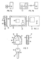
- FIGS. 1a and 1b show a comparison of a process scheme for contactless identification transmission according to the prior art (FIG. 1 a) and a process scheme of the inventive method (FIG. 1 b).
- an identification carrier 1.1 sends out identification signals A, which are received and processed by a reading device 2.1, rsp. be interpreted. Since the identification medium 1.1 represents a system limited by criteria of handling and standardization, its transmission range is particularly limited. In addition, the signals A cannot be varied, that is to say that each reading device 2.1 for which the identification carrier 1.1 is to be applicable must not only receive the signals A but also “understand” them.
- the method according to the invention uses a system "identification carrier with increased range" 1.2 (FIG. 1b), which consists of a standardized identification carrier 1.1 as a subsystem and a relay station 3.
- the relay station 3 has the function of the reading device 2.1 from FIG.
- the relay station 3 sends with a more powerful one Transmitter the corresponding signals B received by a reader 2.2, rsp. be interpreted.
- the signals B correspond to the received signals A in terms of their content, or else the relay station 3 decodes the signals A additionally in accordance with the requirements of the reader 2.2, that is, it translates them into the language of the reader 2.2 and the signals B. then specific identification signals for the reader 2.2.
- the method according to the invention thus uses the identification signals A of a standardized identification carrier 1.1 with a short range and sends identification signals B over an increased range, wherein the identification signals B can also be decoded for a specific reading device.
- This possibility of decoding the identification supplied by the standardized identification carrier (1.1) brings the advantage of the extended range, the advantage of the extended application possibilities also to readers that do not "understand” the identification information of the standardized identification carrier per se.
- the system "identification carrier with increased range" 1.2 thus comprises an identification-dependent part and a reader-dependent part.
- the standardized identification carrier 1.1 in addition to its function as a subsystem of the system 1.2, is also intended to perform its function as a system 1.1, it is advantageous to connect the identification carrier 1.1 and relay station 3 only loosely so that they can be replaced. It is then possible to assign the identification carrier 1.1 of the person to be identified, but the relay station 3 to locations or objects which are associated with the special, far-reaching identification.
- An application example for the method according to the invention relates to access to a building and the associated parking.
- the person to be identified uses an identification card, which they put in an appropriate reader, for access to the building, while they have a relay station for access to the corresponding parking space in the car, in which they insert the same card as a subsystem.
- Another application example are people who use a key or an identification card to access their work place, while doors open automatically within the work place because they carry a relay station with their key or card inserted in their work clothing.
- This second example can also be combined with the first example and then results in a system consisting of different identification-specific parts and different reader-specific parts.
- FIG. 2 shows an exemplary embodiment of the device according to the invention consisting of a standardized, chip-carrying credit card and a correspondingly designed relay station with which the described method according to the invention can be carried out.
- the relay station is designed as a portable sleeve 20, into which a standardized, chip-carrying credit card 21, for example a vision card designed as such, can be inserted into corresponding insertion slots 22 such that the chip 23 integrated in the card is within a reading distance of the reading electronics 24 of the relay station comes to rest.
- the functional elements required in the relay station are: reading, decoding and transmitting electronics 24, current source 25 and antenna 26.
- the credit card 21, as an identification-carrying subsystem, is inserted into the envelope 20, as a relay station.
- the cover can be fastened to clothing, in the car or to other objects using fastening means 27, for example hooks, clips or the like.
- FIG. 3 shows a further exemplary embodiment of the device according to the invention, consisting of a standardized, chip-carrying key 30 and a relay station 31, which has the shape of a cover for the key head.
- the relay station 31 carries the same functional units (24, 25 and 26) as the relay station 20 described in connection with FIG. 2. It has the shape of a shell, through the elastically deformable insertion slot 32 of the head part 33 of the key 30, which carries the chip 34 , is inserted.
- the relay station 31 carries, for example, a hole 35, with the aid of which it can be fastened together with the key, for example to a key ring.
- the envelope 20 described in connection with FIG. 2 for a credit card as a subsystem can be designed such that a key can also be inserted therein in such a way that the identification signals transmitted by it are read by the same electronics 24 as the corresponding signals on the card 21 .
Landscapes
- Engineering & Computer Science (AREA)
- Physics & Mathematics (AREA)
- General Physics & Mathematics (AREA)
- General Engineering & Computer Science (AREA)
- Theoretical Computer Science (AREA)
- Radar Systems Or Details Thereof (AREA)
- Testing Of Coins (AREA)
- Arrangements For Transmission Of Measured Signals (AREA)
- Near-Field Transmission Systems (AREA)
- Credit Cards Or The Like (AREA)
- Electronic Switches (AREA)
Abstract
Für die Erweiterung der Reichweite und der Anwendungsmöglichkeiten der kontaktlosen Identifikationsübertragung von einem normierten, Chip-tragenden Identifikationsträger (1.1), bspw. einer Kreditkarte oder einem Schlüssel, wird ein Verfahren vorgeschlagen, das sich einer Relaisstation (3) zwischen dem Identifikationsträger (1.1) und dem Lesegerät (2.2) bedient. Die Relaisstation (3) empfängt die Identifikationssignale (A) des Identifikationsträgers (1.1), decodiert sie, wenn notwendig, für ein spezifisches Lesegerät (2.2) und sendet sie mit einer grösseren Reichweite wieder aus. Damit der normierte Identifikationsträger (1.1) für Kurzdistanz- (Fig. 1a) und Langdistanz-Anwendungen (Fig. 1b) benutzt werden kann und damit die Relaisstation (3) für Identifikationsträger (1.1) mit verschiedener Identifikation und/oder verschiedener Gestalt benutzt werden kann, ist die Relaisstation (3) so konzipiert, dass der Identifikationsträger (1.1) darauf auswechselbar befestigt werden kann.
Description
Die Erfindung liegt auf dem Gebiete der Schliess- und Sicherheitstechnik und betrifft ein Verfahren und eine Vorrichtung gemäss dem Oberbegriff der unabhängigen Patentansprüche, mit denen die Reichweite der kontaktlosen Übertragung von Identifikationssignalen von normierten Identifikationsträgern erweitert werden kann.The invention is in the field of locking and security technology and relates to a method and a device according to the preamble of the independent claims, with which the range of contactless transmission of identification signals from standardized identification carriers can be expanded.
Die kontaktlose Übertragung von Identifikationssignalen durch einen Chip, der neben der einprogrammierten Identifikationsinformation auch Mittel besitzt, diese Information auszusenden, entspricht dem Stande der Technik. Solche Chips werden beispielsweise in der C2-Card (Contactless Inductive Chip Card), eine Gemeinschaftsentwicklung von ADE, Valvo und ZEISS-Ikon, verwendet und sind zu einem relativ gut verbreiteten Standard entwickelt worden. Die Mass-Norm entspricht dem ISO Kreditkartenformat 7816. Sobald solch ein Chip in den Bereich eines entsprechenden, stationären Sender/Empfängers (Lesegerät) gebracht wird, wird er zum Aussenden der Identifikationssignale angeregt, die vom stationären Empfänger empfangen und entsprechend weiterverarbeitet oder weitergeleitet werden.The contactless transmission of identification signals by means of a chip which, in addition to the programmed identification information, also has means for transmitting this information corresponds to the prior art. Such chips are used, for example, in the C2 card (Contactless Inductive Chip Card), a joint development by ADE, Valvo and ZEISS-Ikon, and have been developed to a relatively well-known standard. The measurement standard corresponds to the ISO credit card format 7816. As soon as such a chip is brought into the area of a corresponding, stationary transmitter / receiver (reader), it is stimulated to send out the identification signals, which are received by the stationary receiver and processed or forwarded accordingly.
Die Reichweite einer solchen kontaktlosen Übertragung von Identifikationssignalen durch einen Chip beträgt etwa 10mm. Das heisst mit anderen Worten, für eine Identifikationsübertragung muss die Chip-tragende Karte oder der Chip-tragende Schlüssel sehr nahe an den entsprechenden Empfänger bewegt werden, also eigentlich wie eine Karte mit nur magnetischen und optischen Identifikationen in einen Schlitz oder wie ein gewöhnlicher Schlüssel in einen Schlüsselkanal gesteckt werden.The range of such contactless transmission of identification signals by a chip is approximately 10 mm. In other words, for an identification transmission, the chip-carrying card or the chip-carrying key must be moved very close to the corresponding receiver, in other words actually like a card with only magnetic and optical identifications in a slot or like an ordinary key in a key channel can be inserted.
Es gibt nun aber viele Fälle, wo eine Identifikation notwendig ist, wo es aber vorteilhaft und bequem wäre, wenn diese nicht auf eine derart kleine Distanz zwischen Identifikations-Sender und Identifikations-Empfänger angewiesen wäre. Entsprechende Anwendungen würden an vielen Orten eingesetzt werden können, bspw. zum automatischen Oeffnen von Türen, wenn der Identifikationsträger sich darauf zu bewegt (ohne das bekannte mühsame Einschieben von Schlüssel oder Karte in eine dafür vorgesehene Apparatur) oder das Oeffnen von Schranken wie beispielsweise Schranken von Parkhäusern und vieles andere mehr.However, there are now many cases where identification is necessary, but where it would be advantageous and convenient if it were not dependent on such a small distance between the identification transmitter and identification receiver. Corresponding applications could be used in many places, for example for automatically opening doors when the identification carrier moves towards them (without the known tedious insertion of a key or card into a device provided for this purpose) or opening barriers such as barriers Parking garages and much more.
Eine Erweiterung der Reichweite ist auf der Chip-tragenden Karte oder auf dem Chip-tragenden Schlüssel nicht ohne weiteres oder nur mit erheblichem Aufwand möglich, da dafür eine Energiequelle, bspw. eine Batterie oder Sonnenzelle, und eine Antenne mit grösserer Reichweite notwendig wäre, die in der Karte oder dem Schlüssel aus räumlichen Gründen nicht mehr untergebracht werden können ohne die gesamte Technologie zu ändern. Grössere Identifikationsträger mit eingebauter Energiequelle unr grösserer Reichweite haben könnten, sind durchaus machbar, aber sie sprengen den Rahmen der Normierung und können deswegen nicht mehr überall eingesetzt werden (Beispiel: Sender plus Magnetspur plus evtl.An extension of the range on the chip-carrying card or on the chip-carrying key is not possible easily or only with considerable effort, since this would require an energy source, for example a battery or solar cell, and an antenna with a longer range, which can no longer be accommodated in the card or key for spatial reasons without changing the entire technology. Larger identification carriers with a built-in energy source and a greater range could be feasible, but they go beyond the scope of standardization and can therefore no longer be used everywhere (example: transmitter plus magnetic track plus possibly
Barcode in einer Vielzweckkarte), da sie dann mit den anderen, der Norm entsprechenden Geräten nicht mehr zusammenarbeiten. Somit sind solche grösseren Identifikationsträger für die normierten Kurzdistanz-Lesegeräte nicht brauchbar und würden die Anzahl notwendiger Idnetifikationsträger in einem Identifikationssystem zudem unnötig erhöhen.Barcode in a multi-purpose card), since they then no longer work together with the other devices that comply with the standard. Such larger identification carriers are therefore not usable for the standardized short-distance reading devices and would also unnecessarily increase the number of identification carriers required in an identification system.
Es ist nun Aufgabe der Erfindung, ein Verfahren aufzuzeigen und eine Vorrichtung zu schaffen, die es erlauben, die Reichweite der kontaktlosen Identifikationsübertragung von einem normierten, Chip-tragenden Identifikationsträger zu erhöhen, ohne dass dadurch die Brauchbarkeit des Identifikaionsträgers für normierte Kurzdistanz-Lesegeräte beeinträchtigt wird. Die Reichweite soll bspw. auf 2m bis 10m, also um einen Faktor von mindestens 200 erhöhbar sein. Die Anwendung solcher Chip-tragender Identifikationsträger soll auch auf eine weitere Palette von Lesegeräten anwendbar sein.It is an object of the invention to demonstrate a method and to provide a device which allows the range of contactless identification transmission from a standardized, chip-carrying identification carrier to be increased without the usability of the identification carrier for standardized short-distance reading devices being impaired thereby . The range should, for example, be increased to 2m to 10m, i.e. by a factor of at least 200. The use of such chip-carrying identification carriers should also be applicable to a further range of reading devices.
Diese Aufgabe wird gelöst durch das Verfahren und die Vorrichtung gemäss den kennzeichnenden Teilen der unabhängigen Patentansprüche. Die folgenden Figuren unterstützen die nachfolgende detaillierte Beschreibung des erfindungsgemässen Verfahrens und der erfindungsgemäsen Vorrichtung. Dabei zeigt
- Fig. 1 das Verfahrensschema des Verfahrens gemäss dem Stande der Technik und des erfindungsgemässen Verfahrens,
- Fig. 2 eine beispielhafte Ausführungsform der erfindungsgemässen Vorrichtung mit einer Chip-tragenden Kreditkarte als Subsystem,
- Fig. 3 eine beispielhafte Ausführungsform der erfindungsgmässen Vorrichtung mit einem Chip-tragenden Schlüssel als Subsystem.
- 1 shows the process diagram of the process according to the prior art and the process according to the invention,
- 2 shows an exemplary embodiment of the device according to the invention with a chip-carrying credit card as a subsystem,
- 3 shows an exemplary embodiment of the device according to the invention with a chip-carrying key as a subsystem.
Das erfindungsgemässe Verfahren besteht prinzipiell darin, eine Art Relaisstation zu benutzen, um die Signale des Identifikations-Chips zu empfangen und mittels eines Senders mit grösserer Reichweite wieder auszustrahlen, damit sie von einem entferntern Lesegerät empfangen werden können.The method according to the invention basically consists in using a kind of relay station to receive the signals of the identification chip and to transmit them again by means of a transmitter with a greater range so that they can be received by a remote reading device.
Die Figuren 1a und 1b zeigen als Vergleich ein Verfahrensschema für die kontaktlose Identifikations-Übertragung gemäss dem Stande der Technik (Fig. 1 a) und ein Verfahrensschema des erfindungsgemässen Verfahrens (Fig. 1 b). Gemäss dem Stande der Technik sendet ein Identifikationsträger 1.1 Identifikationssignale A aus, die von einem Lesegerät 2.1 empfangen und weiterverarbeitet, rsp. interpretiert werden. Da der Identifikationsträger 1.1 ein durch Kriterien der Handhabung und der Normierung beschränktes System darstellt, ist insbesondere seine Sende-Reichweite beschränkt. Zudem sind die Signale A nicht varierbar, das heisst, jedes Lesegerät 2.1, für das der Identifikationsträger 1.1 anwendbar sein soll, muss die Signale A nicht nur empfangen, sondern auch "verstehen" können. FIGS. 1a and 1b show a comparison of a process scheme for contactless identification transmission according to the prior art (FIG. 1 a) and a process scheme of the inventive method (FIG. 1 b). According to the prior art, an identification carrier 1.1 sends out identification signals A, which are received and processed by a reading device 2.1, rsp. be interpreted. Since the identification medium 1.1 represents a system limited by criteria of handling and standardization, its transmission range is particularly limited. In addition, the signals A cannot be varied, that is to say that each reading device 2.1 for which the identification carrier 1.1 is to be applicable must not only receive the signals A but also “understand” them.
Das erfindungsgemässe Verfahren verwendet ein System "Identifikationsträger mit erhöhter Reichweite" 1.2 (Fig. 1b), das aus einem normierten Identifikationsträger 1.1 als Subsystem und einer Relaisstation 3 besteht. Die Relaisstation 3 hat einerseits die Funktion des Lesegerätes 2.1 aus Fig. 1a, das heisst sie empfängt die Identifikationssignale A des Identifikationsträgers 1.1. Andererseits sendet sie mit einem leistungsfähigeren Sender die entsprechenden Signale B aus, die von einem Lesegerät 2.2 empfangen, rsp. interpretiert werden. Je nach Anwendung entsprechen die Signale B in bezug auf ihren Inhalt den empfangenen Signalen A, oder aber die Relaisstation 3 decodiert die Signale A zusätzlich gemäss den Anforderungen des Lesegerätes 2.2, das heisst sie übersetzt sie in die Sprache des Lesegerätes 2.2 und die Signale B sind dann spezifische Identifikationssignale für das Lesegerät 2.2.The method according to the invention uses a system "identification carrier with increased range" 1.2 (FIG. 1b), which consists of a standardized identification carrier 1.1 as a subsystem and a relay station 3. On the one hand, the relay station 3 has the function of the reading device 2.1 from FIG. On the other hand, it sends with a more powerful one Transmitter the corresponding signals B received by a reader 2.2, rsp. be interpreted. Depending on the application, the signals B correspond to the received signals A in terms of their content, or else the relay station 3 decodes the signals A additionally in accordance with the requirements of the reader 2.2, that is, it translates them into the language of the reader 2.2 and the signals B. then specific identification signals for the reader 2.2.
Das erfindungsgemässe Verfahren verwendet also die Idnetifikationssignale A eines normierten Identifikationsträgers 1.1 mit kleiner Reichweite und sendet Identifikationssignale B über eine erhöhte Reichweite aus, wobei zusätzlich die Identifikationssignale B für ein spezifisches Lesegerät decodiert sein können. Diese Möglichkeit der Decodierung der vom normierten Identifikationsträger (1.1) gelieferten Identifikation bringt zum Vorteil der erweiterten Reichweite den Vorteil der erweiterten Anwendungsmöglichkeiten auch auf Lesegeräte, die die Identifikationsinformation des normierten Identifikationsträgers an sich nicht "verstehen".The method according to the invention thus uses the identification signals A of a standardized identification carrier 1.1 with a short range and sends identification signals B over an increased range, wherein the identification signals B can also be decoded for a specific reading device. This possibility of decoding the identification supplied by the standardized identification carrier (1.1) brings the advantage of the extended range, the advantage of the extended application possibilities also to readers that do not "understand" the identification information of the standardized identification carrier per se.
Das System "Identifikationsträger mit erhöhter Reichweite" 1.2 umfasst also einen Identifikations-abhängigen Teil und einen Lesegerät-abhängigen Teil. Aus diesem Grunde und auch, weil der normierte Identifikationsträger 1.1 neben seiner Funktion als Subsystem des Systems 1.2 gleichzeitig seine Funktion als System 1.1 wahrnehmen soll, ist es vorteilhaft, Identifikationsträger 1.1 und Relaisstation 3 nur lose miteinander zu verbinden, damit sie auswechselbar sind. Dann ist es möglich, den Identifikationsträger 1.1 der zu identifizierenden Person, die Relaisstation 3 aber Örtlichkeiten oder Gegenständen zuzuordnen, die mit der speziellen weitreichenden Identifikation in Verbindung stehen.The system "identification carrier with increased range" 1.2 thus comprises an identification-dependent part and a reader-dependent part. For this reason and also because the standardized identification carrier 1.1, in addition to its function as a subsystem of the system 1.2, is also intended to perform its function as a system 1.1, it is advantageous to connect the identification carrier 1.1 and relay station 3 only loosely so that they can be replaced. It is then possible to assign the identification carrier 1.1 of the person to be identified, but the relay station 3 to locations or objects which are associated with the special, far-reaching identification.
Ein Anwendungsbeispiel für das erfindungsgemässe Verfahren betrifft den Zutritt zu einem Gebäude und dem dazugehörenden Parking. Die zu identifizierende Person benutzt eine Identifikationskarte, die sie in ein entsprechendes Lesegerät steckt, für den Zutritt zum Gebäude, während sie für die Zufahrt zum entsprechenden Parkplatz im Auto eine Relaisstation hat, in die sie die gleiche Karte als Subsystem steckt.An application example for the method according to the invention relates to access to a building and the associated parking. The person to be identified uses an identification card, which they put in an appropriate reader, for access to the building, while they have a relay station for access to the corresponding parking space in the car, in which they insert the same card as a subsystem.
Ein weiteres Anwendungsbeispiel sind Personen, die für den Zutritt zu ihrer Arbeitsstelle einen Schlüssel oder eine Identifikationskarte benutzen, während sich ihnen innerhalb der Arbeitsstelle Türen automatisch öffnen, weil sie an ihrer Werkkleidung eine Relaisstation mit dem eingesteckten Schlüssel oder der eingesteckten Karte tragen. Dieses zweite Beispiel lässt sich auch mit dem ersten Beispiel kombinieren und ergibt dann ein System bestehend aus verschiedenen Identifikations-spezifischen Teilen und verschiedenen Lesegerät-spezifischen Teilen.Another application example are people who use a key or an identification card to access their work place, while doors open automatically within the work place because they carry a relay station with their key or card inserted in their work clothing. This second example can also be combined with the first example and then results in a system consisting of different identification-specific parts and different reader-specific parts.
Figur 2 zeigt eine beispielhafte Ausführungsform der erfindungsgemässen Vorrichtung bestehend aus einer normierten, Chip-tragenden Kreditkarte und einer entsprechend gestalteten Relaisstation, mit der das beschriebene, erfindungsgemässe Verfahren durchgeführt werden kann. Die Relais-station ist als portable Hülle 20 ausgebildet, in die eine normierte, Chip-tragende Kreditkarte 21, beispielsweise ein als solche ausgebildeter Sichtausweis, derart in entsprechende Einschiebeschlitze 22 eingesteckt werden kann, dass der in der Karte integrierte Chip 23 in Lesedistanz zur Leseelektronik 24 der Relaisstation zu liegen kommt. Die in der Relaisstation notwendigen Funktionselemente sind: Lese-, Decodier- und Sende-elektronik 24, Stromquelle 25 und Antenne 26. FIG. 2 shows an exemplary embodiment of the device according to the invention consisting of a standardized, chip-carrying credit card and a correspondingly designed relay station with which the described method according to the invention can be carried out. The relay station is designed as a
Die Kreditkarte 21, als Identifikations-tragendes Subsystem, wird in die Hülle 20, als Relaisstation, eingeschoben. Die Hülle ist mit Hilfe von Befestigungsmitteln 27, beispielsweise Haken, Klammern oder Ähnliches, an Kleidung, im Auto oder an anderen Gegenständen befestigbar.The credit card 21, as an identification-carrying subsystem, is inserted into the
Figur 3 zeigt eine weitere beispielhafte Ausführungsform der erfindungsgemässen Vorrichtung, bestehend aus einem normierten, Chip-tragenden Schlüssel 30 und einer Relaisstation 31, die die Form einer Hülle für den Schlüsselkopf hat. Die Relaisstation 31 trägt dieselben Funktionseinheiten (24, 25 und 26) wie die im Zusammenhang mit der Figur 2 beschriebene Relaisstation 20. Sie hat die Form einer Hülle, durch deren elastisch deformierbaren Einschiebeschlitz 32 der Kopfteil 33 des Schlüssels 30, der den Chip 34 trägt, eingesteckt wird. Für Befestigungszwecke trägt die Relaisstation 31 zum Beispiel ein Loch 35, mit Hilfe dessen sie samt Schlüssel beispielsweise an einem Schlüsselanhänger befestigt werden kann. FIG. 3 shows a further exemplary embodiment of the device according to the invention, consisting of a standardized, chip-carrying
Weitere Ausführungsvarianten der erfindungsgemässen Vorrichtung ergeben sich durch Kombination der den beschriebenen Ausführungsformen zu Grunde liegenden Ideen. Beispielsweise kann die im Zusammenhang mit der Figur 2 beschriebene Hülle 20 für eine Kreditkarte als Subsystem derart ausgebildet sein, dass darin ebenfalls ein Schlüssel derart eingesteckt werden kann, dass die von ihm ausgesendeten Identifikationssignale von derselben Elektronik 24 gelesen wird wie die entsprechenden Signale der Karte 21.Further design variants of the device according to the invention result from a combination of the ideas on which the described embodiments are based. For example, the
Claims (11)
Applications Claiming Priority (2)
| Application Number | Priority Date | Filing Date | Title |
|---|---|---|---|
| CH889/90 | 1990-03-19 | ||
| CH88990 | 1990-03-19 |
Publications (3)
| Publication Number | Publication Date |
|---|---|
| EP0448507A2 true EP0448507A2 (en) | 1991-09-25 |
| EP0448507A3 EP0448507A3 (en) | 1992-05-06 |
| EP0448507B1 EP0448507B1 (en) | 1995-12-06 |
Family
ID=4197547
Family Applications (1)
| Application Number | Title | Priority Date | Filing Date |
|---|---|---|---|
| EP91810092A Expired - Lifetime EP0448507B1 (en) | 1990-03-19 | 1991-02-08 | Contactless transmission of identification signals |
Country Status (6)
| Country | Link |
|---|---|
| EP (1) | EP0448507B1 (en) |
| AT (1) | ATE131296T1 (en) |
| DE (1) | DE59107004D1 (en) |
| DK (1) | DK0448507T3 (en) |
| ES (1) | ES2083554T3 (en) |
| GR (1) | GR3018326T3 (en) |
Cited By (6)
| Publication number | Priority date | Publication date | Assignee | Title |
|---|---|---|---|---|
| DE4201967A1 (en) * | 1992-01-23 | 1993-07-29 | Deutsche Telephonwerk Kabel | Protecting integrity of printed or embossed data on e.g. credit card - has terminal contg. processor coupled to printer with reference values generated for comparison check |
| DE9210910U1 (en) * | 1992-08-14 | 1993-09-16 | Siemens AG, 80333 München | Data processing device, in particular for workpiece identification |
| EP0562622A1 (en) * | 1992-03-27 | 1993-09-29 | Shinko Electric Co. Ltd. | ID recognizing system in semiconductor manufacturing system |
| EP0559605A3 (en) * | 1992-03-04 | 1995-06-21 | Bauer Kaba Ag | Individual identification system |
| FR2741734A1 (en) * | 1995-11-27 | 1997-05-30 | France Telecom | Sleeve for protection of smart card used with telephone or card reader |
| WO1999021741A1 (en) * | 1997-10-29 | 1999-05-06 | Robert Bosch Gmbh | Drive authorization system for motor vehicles |
Family Cites Families (3)
| Publication number | Priority date | Publication date | Assignee | Title |
|---|---|---|---|---|
| FI841986A7 (en) * | 1984-05-17 | 1985-11-18 | Waertsilae Oy Ab | DISPOSAL SYSTEM. |
| US4829166A (en) * | 1986-12-01 | 1989-05-09 | Froelich Ronald W | Computerized data-bearing card and reader/writer therefor |
| FR2636153B2 (en) * | 1988-06-08 | 1992-10-09 | Parienti Raoul | MEMORY BI-MODULE CHIP CARD AND REMOTE USE DEVICE |
-
1991
- 1991-02-08 EP EP91810092A patent/EP0448507B1/en not_active Expired - Lifetime
- 1991-02-08 DE DE59107004T patent/DE59107004D1/en not_active Expired - Lifetime
- 1991-02-08 AT AT91810092T patent/ATE131296T1/en not_active IP Right Cessation
- 1991-02-08 DK DK91810092.6T patent/DK0448507T3/en not_active Application Discontinuation
- 1991-02-08 ES ES91810092T patent/ES2083554T3/en not_active Expired - Lifetime
-
1995
- 1995-12-07 GR GR950403433T patent/GR3018326T3/en unknown
Cited By (7)
| Publication number | Priority date | Publication date | Assignee | Title |
|---|---|---|---|---|
| DE4201967A1 (en) * | 1992-01-23 | 1993-07-29 | Deutsche Telephonwerk Kabel | Protecting integrity of printed or embossed data on e.g. credit card - has terminal contg. processor coupled to printer with reference values generated for comparison check |
| EP0559605A3 (en) * | 1992-03-04 | 1995-06-21 | Bauer Kaba Ag | Individual identification system |
| EP0562622A1 (en) * | 1992-03-27 | 1993-09-29 | Shinko Electric Co. Ltd. | ID recognizing system in semiconductor manufacturing system |
| US5389769A (en) * | 1992-03-27 | 1995-02-14 | Shinko Electric Co., Ltd. | ID recognizing system in semiconductor manufacturing system |
| DE9210910U1 (en) * | 1992-08-14 | 1993-09-16 | Siemens AG, 80333 München | Data processing device, in particular for workpiece identification |
| FR2741734A1 (en) * | 1995-11-27 | 1997-05-30 | France Telecom | Sleeve for protection of smart card used with telephone or card reader |
| WO1999021741A1 (en) * | 1997-10-29 | 1999-05-06 | Robert Bosch Gmbh | Drive authorization system for motor vehicles |
Also Published As
| Publication number | Publication date |
|---|---|
| DE59107004D1 (en) | 1996-01-18 |
| EP0448507B1 (en) | 1995-12-06 |
| DK0448507T3 (en) | 1996-01-02 |
| EP0448507A3 (en) | 1992-05-06 |
| ES2083554T3 (en) | 1996-04-16 |
| GR3018326T3 (en) | 1996-03-31 |
| ATE131296T1 (en) | 1995-12-15 |
Similar Documents
| Publication | Publication Date | Title |
|---|---|---|
| DE69231534T2 (en) | Smart card for remote identification | |
| DE69430092T2 (en) | Arrangement for the simultaneous interrogation of many portable radio frequency communication devices | |
| DE69332198T2 (en) | Bidirectional communication system with double resonance antenna circuit for RF trailers | |
| DE68906177T2 (en) | TICKET PAYMENT SYSTEM FOR TRANSPORTATION USERS. | |
| EP0590122B1 (en) | Process and system for transmitting serial data structures for information carrier identification systems, and information carriers | |
| EP1763820B1 (en) | Transponder unit | |
| DE3786836T2 (en) | Microwave data transmission device. | |
| DE60007995T2 (en) | METHOD AND DEVICE FOR DETECTING PERSONS OR OBJECTS IN A DEFINED ROOM WITH AN ENTRANCE | |
| DE69200097T2 (en) | Communication system between a fixed station and mobile stations. | |
| DE69700590T2 (en) | DEVICE FOR CONTACTLESS DATA EXCHANGE WITH A NON-ELECTRONIC LABEL | |
| EP0079047A2 (en) | Identification card | |
| DD269478A5 (en) | ELECTRONIC DATA PROCESSING SYSTEM | |
| EP0562292A1 (en) | Remote transmission contactless chip card | |
| EP0815530B1 (en) | Method and device for adapting a chip card to different card terminals | |
| DE60303824T2 (en) | INVENTORY PROCEDURE FOR TRANSPONDER BY MEANS OF A COMMUNICATION STATION | |
| DE69404966T2 (en) | Device for contactless identification of objects, in particular metallic objects | |
| DE60305433T2 (en) | Communication between electromagnetic transponders | |
| EP0848564A2 (en) | Method for transmitting local informations to a mobile transceiver | |
| EP0448507B1 (en) | Contactless transmission of identification signals | |
| DE69929764T2 (en) | Improved process for identification of smart cards | |
| DE4205827C2 (en) | Chip card for contactless, bidirectional transmission of energy and data with a read / write device | |
| DE4311385C2 (en) | Identification card | |
| DE69908917T2 (en) | METHOD, SYSTEM AND DEVICE FOR THE ELECTROMAGNETIC TRANSFER OF INFORMATION BETWEEN READERS AND NOMADIC OBJECTS | |
| DE19748327A1 (en) | Antenna device, in particular for an anti-theft system of a motor vehicle | |
| DE10352734A1 (en) | Radio frequency identification device |
Legal Events
| Date | Code | Title | Description |
|---|---|---|---|
| PUAI | Public reference made under article 153(3) epc to a published international application that has entered the european phase |
Free format text: ORIGINAL CODE: 0009012 |
|
| AK | Designated contracting states |
Kind code of ref document: A2 Designated state(s): AT BE CH DE DK ES FR GB GR IT LI LU NL SE |
|
| PUAL | Search report despatched |
Free format text: ORIGINAL CODE: 0009013 |
|
| AK | Designated contracting states |
Kind code of ref document: A3 Designated state(s): AT BE CH DE DK ES FR GB GR IT LI LU NL SE |
|
| 17P | Request for examination filed |
Effective date: 19920908 |
|
| RAP1 | Party data changed (applicant data changed or rights of an application transferred) |
Owner name: BAUER KABA AG |
|
| 17Q | First examination report despatched |
Effective date: 19950208 |
|
| ITF | It: translation for a ep patent filed | ||
| GRAA | (expected) grant |
Free format text: ORIGINAL CODE: 0009210 |
|
| AK | Designated contracting states |
Kind code of ref document: B1 Designated state(s): AT BE CH DE DK ES FR GB GR IT LI LU NL SE |
|
| REF | Corresponds to: |
Ref document number: 131296 Country of ref document: AT Date of ref document: 19951215 Kind code of ref document: T |
|
| REG | Reference to a national code |
Ref country code: DK Ref legal event code: T3 |
|
| GBT | Gb: translation of ep patent filed (gb section 77(6)(a)/1977) |
Effective date: 19951207 |
|
| REF | Corresponds to: |
Ref document number: 59107004 Country of ref document: DE Date of ref document: 19960118 |
|
| ET | Fr: translation filed | ||
| REG | Reference to a national code |
Ref country code: CH Ref legal event code: NV Representative=s name: FREI PATENTANWALTSBUERO |
|
| REG | Reference to a national code |
Ref country code: GR Ref legal event code: FG4A Free format text: 3018326 |
|
| REG | Reference to a national code |
Ref country code: ES Ref legal event code: FG2A Ref document number: 2083554 Country of ref document: ES Kind code of ref document: T3 |
|
| PLBE | No opposition filed within time limit |
Free format text: ORIGINAL CODE: 0009261 |
|
| 26N | No opposition filed | ||
| NLT1 | Nl: modifications of names registered in virtue of documents presented to the patent office pursuant to art. 16 a, paragraph 1 |
Owner name: KABA SCHLIESSSYSTEME AG |
|
| REG | Reference to a national code |
Ref country code: FR Ref legal event code: CD |
|
| PGFP | Annual fee paid to national office [announced via postgrant information from national office to epo] |
Ref country code: GR Payment date: 19980129 Year of fee payment: 8 Ref country code: SE Payment date: 19980129 Year of fee payment: 8 |
|
| PGFP | Annual fee paid to national office [announced via postgrant information from national office to epo] |
Ref country code: DK Payment date: 19980224 Year of fee payment: 8 |
|
| PGFP | Annual fee paid to national office [announced via postgrant information from national office to epo] |
Ref country code: LU Payment date: 19980303 Year of fee payment: 8 |
|
| PG25 | Lapsed in a contracting state [announced via postgrant information from national office to epo] |
Ref country code: LU Free format text: LAPSE BECAUSE OF NON-PAYMENT OF DUE FEES Effective date: 19990208 |
|
| PG25 | Lapsed in a contracting state [announced via postgrant information from national office to epo] |
Ref country code: SE Free format text: LAPSE BECAUSE OF NON-PAYMENT OF DUE FEES Effective date: 19990209 |
|
| PG25 | Lapsed in a contracting state [announced via postgrant information from national office to epo] |
Ref country code: GR Free format text: LAPSE BECAUSE OF NON-PAYMENT OF DUE FEES Effective date: 19990228 |
|
| PG25 | Lapsed in a contracting state [announced via postgrant information from national office to epo] |
Ref country code: DK Free format text: LAPSE BECAUSE OF NON-PAYMENT OF DUE FEES Effective date: 19990301 |
|
| EUG | Se: european patent has lapsed |
Ref document number: 91810092.6 |
|
| REG | Reference to a national code |
Ref country code: DK Ref legal event code: EBP |
|
| REG | Reference to a national code |
Ref country code: GB Ref legal event code: IF02 |
|
| PGFP | Annual fee paid to national office [announced via postgrant information from national office to epo] |
Ref country code: BE Payment date: 20050216 Year of fee payment: 15 |
|
| PGFP | Annual fee paid to national office [announced via postgrant information from national office to epo] |
Ref country code: GB Payment date: 20060202 Year of fee payment: 16 |
|
| PGFP | Annual fee paid to national office [announced via postgrant information from national office to epo] |
Ref country code: ES Payment date: 20060216 Year of fee payment: 16 |
|
| PGFP | Annual fee paid to national office [announced via postgrant information from national office to epo] |
Ref country code: AT Payment date: 20060222 Year of fee payment: 16 |
|
| PGFP | Annual fee paid to national office [announced via postgrant information from national office to epo] |
Ref country code: FR Payment date: 20060227 Year of fee payment: 16 |
|
| PG25 | Lapsed in a contracting state [announced via postgrant information from national office to epo] |
Ref country code: BE Free format text: LAPSE BECAUSE OF NON-PAYMENT OF DUE FEES Effective date: 20060228 |
|
| PGFP | Annual fee paid to national office [announced via postgrant information from national office to epo] |
Ref country code: IT Payment date: 20060228 Year of fee payment: 16 |
|
| GBPC | Gb: european patent ceased through non-payment of renewal fee |
Effective date: 20070208 |
|
| PG25 | Lapsed in a contracting state [announced via postgrant information from national office to epo] |
Ref country code: AT Free format text: LAPSE BECAUSE OF NON-PAYMENT OF DUE FEES Effective date: 20070208 |
|
| REG | Reference to a national code |
Ref country code: FR Ref legal event code: ST Effective date: 20071030 |
|
| BERE | Be: lapsed |
Owner name: *BAUER SCHLIESSSYSTEME A.G. Effective date: 20060228 |
|
| PG25 | Lapsed in a contracting state [announced via postgrant information from national office to epo] |
Ref country code: GB Free format text: LAPSE BECAUSE OF NON-PAYMENT OF DUE FEES Effective date: 20070208 Ref country code: FR Free format text: LAPSE BECAUSE OF NON-PAYMENT OF DUE FEES Effective date: 20070228 |
|
| REG | Reference to a national code |
Ref country code: ES Ref legal event code: FD2A Effective date: 20070209 |
|
| PG25 | Lapsed in a contracting state [announced via postgrant information from national office to epo] |
Ref country code: ES Free format text: LAPSE BECAUSE OF NON-PAYMENT OF DUE FEES Effective date: 20070209 |
|
| PG25 | Lapsed in a contracting state [announced via postgrant information from national office to epo] |
Ref country code: IT Free format text: LAPSE BECAUSE OF NON-PAYMENT OF DUE FEES Effective date: 20070208 |
|
| PGFP | Annual fee paid to national office [announced via postgrant information from national office to epo] |
Ref country code: CH Payment date: 20100108 Year of fee payment: 20 |
|
| PGFP | Annual fee paid to national office [announced via postgrant information from national office to epo] |
Ref country code: DE Payment date: 20100219 Year of fee payment: 20 |
|
| PGFP | Annual fee paid to national office [announced via postgrant information from national office to epo] |
Ref country code: NL Payment date: 20100215 Year of fee payment: 20 |
|
| REG | Reference to a national code |
Ref country code: DE Ref legal event code: R071 Ref document number: 59107004 Country of ref document: DE |
|
| REG | Reference to a national code |
Ref country code: CH Ref legal event code: PL |
|
| REG | Reference to a national code |
Ref country code: NL Ref legal event code: V4 Effective date: 20110208 |
|
| PG25 | Lapsed in a contracting state [announced via postgrant information from national office to epo] |
Ref country code: NL Free format text: LAPSE BECAUSE OF EXPIRATION OF PROTECTION Effective date: 20110208 |
|
| PG25 | Lapsed in a contracting state [announced via postgrant information from national office to epo] |
Ref country code: DE Free format text: LAPSE BECAUSE OF EXPIRATION OF PROTECTION Effective date: 20110208 |