EP0448507A2 - Transmission sans contact de signaux d'identification - Google Patents
Transmission sans contact de signaux d'identification Download PDFInfo
- Publication number
- EP0448507A2 EP0448507A2 EP91810092A EP91810092A EP0448507A2 EP 0448507 A2 EP0448507 A2 EP 0448507A2 EP 91810092 A EP91810092 A EP 91810092A EP 91810092 A EP91810092 A EP 91810092A EP 0448507 A2 EP0448507 A2 EP 0448507A2
- Authority
- EP
- European Patent Office
- Prior art keywords
- identification
- relay station
- standardized
- chip
- carrier
- Prior art date
- Legal status (The legal status is an assumption and is not a legal conclusion. Google has not performed a legal analysis and makes no representation as to the accuracy of the status listed.)
- Granted
Links
Images
Classifications
-
- G—PHYSICS
- G06—COMPUTING OR CALCULATING; COUNTING
- G06K—GRAPHICAL DATA READING; PRESENTATION OF DATA; RECORD CARRIERS; HANDLING RECORD CARRIERS
- G06K17/00—Methods or arrangements for effecting co-operative working between equipments covered by two or more of main groups G06K1/00 - G06K15/00, e.g. automatic card files incorporating conveying and reading operations
- G06K17/0022—Methods or arrangements for effecting co-operative working between equipments covered by two or more of main groups G06K1/00 - G06K15/00, e.g. automatic card files incorporating conveying and reading operations arrangements or provisions for transferring data to distant stations, e.g. from a sensing device
-
- G—PHYSICS
- G07—CHECKING-DEVICES
- G07C—TIME OR ATTENDANCE REGISTERS; REGISTERING OR INDICATING THE WORKING OF MACHINES; GENERATING RANDOM NUMBERS; VOTING OR LOTTERY APPARATUS; ARRANGEMENTS, SYSTEMS OR APPARATUS FOR CHECKING NOT PROVIDED FOR ELSEWHERE
- G07C9/00—Individual registration on entry or exit
- G07C9/20—Individual registration on entry or exit involving the use of a pass
- G07C9/28—Individual registration on entry or exit involving the use of a pass the pass enabling tracking or indicating presence
Definitions
- the invention is in the field of locking and security technology and relates to a method and a device according to the preamble of the independent claims, with which the range of contactless transmission of identification signals from standardized identification carriers can be expanded.
- the contactless transmission of identification signals by means of a chip which, in addition to the programmed identification information, also has means for transmitting this information corresponds to the prior art.
- Such chips are used, for example, in the C2 card (Contactless Inductive Chip Card), a joint development by ADE, Valvo and ZEISS-Ikon, and have been developed to a relatively well-known standard.
- the measurement standard corresponds to the ISO credit card format 7816.
- the range of such contactless transmission of identification signals by a chip is approximately 10 mm.
- the chip-carrying card or the chip-carrying key must be moved very close to the corresponding receiver, in other words actually like a card with only magnetic and optical identifications in a slot or like an ordinary key in a key channel can be inserted.
- the range should, for example, be increased to 2m to 10m, i.e. by a factor of at least 200.
- the use of such chip-carrying identification carriers should also be applicable to a further range of reading devices.
- the method according to the invention basically consists in using a kind of relay station to receive the signals of the identification chip and to transmit them again by means of a transmitter with a greater range so that they can be received by a remote reading device.
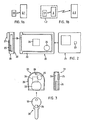
- FIGS. 1a and 1b show a comparison of a process scheme for contactless identification transmission according to the prior art (FIG. 1 a) and a process scheme of the inventive method (FIG. 1 b).
- an identification carrier 1.1 sends out identification signals A, which are received and processed by a reading device 2.1, rsp. be interpreted. Since the identification medium 1.1 represents a system limited by criteria of handling and standardization, its transmission range is particularly limited. In addition, the signals A cannot be varied, that is to say that each reading device 2.1 for which the identification carrier 1.1 is to be applicable must not only receive the signals A but also “understand” them.
- the method according to the invention uses a system "identification carrier with increased range" 1.2 (FIG. 1b), which consists of a standardized identification carrier 1.1 as a subsystem and a relay station 3.
- the relay station 3 has the function of the reading device 2.1 from FIG.
- the relay station 3 sends with a more powerful one Transmitter the corresponding signals B received by a reader 2.2, rsp. be interpreted.
- the signals B correspond to the received signals A in terms of their content, or else the relay station 3 decodes the signals A additionally in accordance with the requirements of the reader 2.2, that is, it translates them into the language of the reader 2.2 and the signals B. then specific identification signals for the reader 2.2.
- the method according to the invention thus uses the identification signals A of a standardized identification carrier 1.1 with a short range and sends identification signals B over an increased range, wherein the identification signals B can also be decoded for a specific reading device.
- This possibility of decoding the identification supplied by the standardized identification carrier (1.1) brings the advantage of the extended range, the advantage of the extended application possibilities also to readers that do not "understand” the identification information of the standardized identification carrier per se.
- the system "identification carrier with increased range" 1.2 thus comprises an identification-dependent part and a reader-dependent part.
- the standardized identification carrier 1.1 in addition to its function as a subsystem of the system 1.2, is also intended to perform its function as a system 1.1, it is advantageous to connect the identification carrier 1.1 and relay station 3 only loosely so that they can be replaced. It is then possible to assign the identification carrier 1.1 of the person to be identified, but the relay station 3 to locations or objects which are associated with the special, far-reaching identification.
- An application example for the method according to the invention relates to access to a building and the associated parking.
- the person to be identified uses an identification card, which they put in an appropriate reader, for access to the building, while they have a relay station for access to the corresponding parking space in the car, in which they insert the same card as a subsystem.
- Another application example are people who use a key or an identification card to access their work place, while doors open automatically within the work place because they carry a relay station with their key or card inserted in their work clothing.
- This second example can also be combined with the first example and then results in a system consisting of different identification-specific parts and different reader-specific parts.
- FIG. 2 shows an exemplary embodiment of the device according to the invention consisting of a standardized, chip-carrying credit card and a correspondingly designed relay station with which the described method according to the invention can be carried out.
- the relay station is designed as a portable sleeve 20, into which a standardized, chip-carrying credit card 21, for example a vision card designed as such, can be inserted into corresponding insertion slots 22 such that the chip 23 integrated in the card is within a reading distance of the reading electronics 24 of the relay station comes to rest.
- the functional elements required in the relay station are: reading, decoding and transmitting electronics 24, current source 25 and antenna 26.
- the credit card 21, as an identification-carrying subsystem, is inserted into the envelope 20, as a relay station.
- the cover can be fastened to clothing, in the car or to other objects using fastening means 27, for example hooks, clips or the like.
- FIG. 3 shows a further exemplary embodiment of the device according to the invention, consisting of a standardized, chip-carrying key 30 and a relay station 31, which has the shape of a cover for the key head.
- the relay station 31 carries the same functional units (24, 25 and 26) as the relay station 20 described in connection with FIG. 2. It has the shape of a shell, through the elastically deformable insertion slot 32 of the head part 33 of the key 30, which carries the chip 34 , is inserted.
- the relay station 31 carries, for example, a hole 35, with the aid of which it can be fastened together with the key, for example to a key ring.
- the envelope 20 described in connection with FIG. 2 for a credit card as a subsystem can be designed such that a key can also be inserted therein in such a way that the identification signals transmitted by it are read by the same electronics 24 as the corresponding signals on the card 21 .
Landscapes
- Engineering & Computer Science (AREA)
- Physics & Mathematics (AREA)
- General Physics & Mathematics (AREA)
- General Engineering & Computer Science (AREA)
- Theoretical Computer Science (AREA)
- Radar Systems Or Details Thereof (AREA)
- Testing Of Coins (AREA)
- Arrangements For Transmission Of Measured Signals (AREA)
- Near-Field Transmission Systems (AREA)
- Credit Cards Or The Like (AREA)
- Electronic Switches (AREA)
Applications Claiming Priority (2)
| Application Number | Priority Date | Filing Date | Title |
|---|---|---|---|
| CH889/90 | 1990-03-19 | ||
| CH88990 | 1990-03-19 |
Publications (3)
| Publication Number | Publication Date |
|---|---|
| EP0448507A2 true EP0448507A2 (fr) | 1991-09-25 |
| EP0448507A3 EP0448507A3 (en) | 1992-05-06 |
| EP0448507B1 EP0448507B1 (fr) | 1995-12-06 |
Family
ID=4197547
Family Applications (1)
| Application Number | Title | Priority Date | Filing Date |
|---|---|---|---|
| EP91810092A Expired - Lifetime EP0448507B1 (fr) | 1990-03-19 | 1991-02-08 | Transmission sans contact de signaux d'identification |
Country Status (6)
| Country | Link |
|---|---|
| EP (1) | EP0448507B1 (fr) |
| AT (1) | ATE131296T1 (fr) |
| DE (1) | DE59107004D1 (fr) |
| DK (1) | DK0448507T3 (fr) |
| ES (1) | ES2083554T3 (fr) |
| GR (1) | GR3018326T3 (fr) |
Cited By (6)
| Publication number | Priority date | Publication date | Assignee | Title |
|---|---|---|---|---|
| DE4201967A1 (de) * | 1992-01-23 | 1993-07-29 | Deutsche Telephonwerk Kabel | Verfahren und anordnung zum sicherstellen der integritaet von auszudruckenden oder zu stempelnden daten |
| DE9210910U1 (de) * | 1992-08-14 | 1993-09-16 | Siemens AG, 80333 München | Datenverarbeitungsvorrichtung insbesondere zur Werkstückidentifikation |
| EP0562622A1 (fr) * | 1992-03-27 | 1993-09-29 | Shinko Electric Co. Ltd. | Système pour reconnaître des marques d'identification dans une usine de fabrication des semi-conducteurs |
| EP0559605A3 (en) * | 1992-03-04 | 1995-06-21 | Bauer Kaba Ag | Individual identification system |
| FR2741734A1 (fr) * | 1995-11-27 | 1997-05-30 | France Telecom | Etui de protection pour carte d'authentification a puce utilisable a partir d'un terminal telephonique ou d'un lecteur de cartes a puce |
| WO1999021741A1 (fr) * | 1997-10-29 | 1999-05-06 | Robert Bosch Gmbh | Systeme d'autorisation de roulement, en particulier pour vehicules automobiles |
Family Cites Families (3)
| Publication number | Priority date | Publication date | Assignee | Title |
|---|---|---|---|---|
| FI841986A7 (fi) * | 1984-05-17 | 1985-11-18 | Waertsilae Oy Ab | Laosningssystem. |
| US4829166A (en) * | 1986-12-01 | 1989-05-09 | Froelich Ronald W | Computerized data-bearing card and reader/writer therefor |
| FR2636153B2 (fr) * | 1988-06-08 | 1992-10-09 | Parienti Raoul | Carte a puce bi-module memoire et son dispositif d'utilisation a distance |
-
1991
- 1991-02-08 EP EP91810092A patent/EP0448507B1/fr not_active Expired - Lifetime
- 1991-02-08 DE DE59107004T patent/DE59107004D1/de not_active Expired - Lifetime
- 1991-02-08 AT AT91810092T patent/ATE131296T1/de not_active IP Right Cessation
- 1991-02-08 DK DK91810092.6T patent/DK0448507T3/da not_active Application Discontinuation
- 1991-02-08 ES ES91810092T patent/ES2083554T3/es not_active Expired - Lifetime
-
1995
- 1995-12-07 GR GR950403433T patent/GR3018326T3/el unknown
Cited By (7)
| Publication number | Priority date | Publication date | Assignee | Title |
|---|---|---|---|---|
| DE4201967A1 (de) * | 1992-01-23 | 1993-07-29 | Deutsche Telephonwerk Kabel | Verfahren und anordnung zum sicherstellen der integritaet von auszudruckenden oder zu stempelnden daten |
| EP0559605A3 (en) * | 1992-03-04 | 1995-06-21 | Bauer Kaba Ag | Individual identification system |
| EP0562622A1 (fr) * | 1992-03-27 | 1993-09-29 | Shinko Electric Co. Ltd. | Système pour reconnaître des marques d'identification dans une usine de fabrication des semi-conducteurs |
| US5389769A (en) * | 1992-03-27 | 1995-02-14 | Shinko Electric Co., Ltd. | ID recognizing system in semiconductor manufacturing system |
| DE9210910U1 (de) * | 1992-08-14 | 1993-09-16 | Siemens AG, 80333 München | Datenverarbeitungsvorrichtung insbesondere zur Werkstückidentifikation |
| FR2741734A1 (fr) * | 1995-11-27 | 1997-05-30 | France Telecom | Etui de protection pour carte d'authentification a puce utilisable a partir d'un terminal telephonique ou d'un lecteur de cartes a puce |
| WO1999021741A1 (fr) * | 1997-10-29 | 1999-05-06 | Robert Bosch Gmbh | Systeme d'autorisation de roulement, en particulier pour vehicules automobiles |
Also Published As
| Publication number | Publication date |
|---|---|
| DE59107004D1 (de) | 1996-01-18 |
| EP0448507B1 (fr) | 1995-12-06 |
| DK0448507T3 (da) | 1996-01-02 |
| EP0448507A3 (en) | 1992-05-06 |
| ES2083554T3 (es) | 1996-04-16 |
| GR3018326T3 (en) | 1996-03-31 |
| ATE131296T1 (de) | 1995-12-15 |
Similar Documents
| Publication | Publication Date | Title |
|---|---|---|
| DE69231534T2 (de) | Chipkarte für die Fernidentifizierung | |
| DE69430092T2 (de) | Anordnung zur gleichzeitigen Abfrage vieler tragbarer Funkfrequenz-Kommunikationsgeräte | |
| DE69332198T2 (de) | Bidirektionales-Kommunikationssystem mit Doppelresonanz-Antennenschaltung für RF-Anhänger | |
| DE68906177T2 (de) | Fahrgeldbezahlsystem fuer benutzer von verkehrsmitteln. | |
| EP0590122B1 (fr) | Procede et systeme de transmission de structures serielles de donnees pour systemes d'identification de supports d'information, ainsi que support d'information | |
| EP1763820B1 (fr) | Unite de transpondeur | |
| DE3786836T2 (de) | Mikrowellen-Datenübertragungsgerät. | |
| DE60007995T2 (de) | Verfahren und vorrichtung zur detektion von personen oder objekten in einem abgegrenzten raum mit einem eingang | |
| DE69200097T2 (de) | Kommunikationsanlage zwischen einer ortsgebundenen Station und mobilen Stationen. | |
| DE69700590T2 (de) | Vorrichtung zum kontaktlosen datenaustausch mit einem nichtelektronischen etikett | |
| EP0079047A2 (fr) | Carte d'identité | |
| DD269478A5 (de) | Elektronisches datenverarbeitungssystem | |
| EP0562292A1 (fr) | Carte à puce sans contact avec transmission à distance | |
| EP0815530B1 (fr) | Procede et dispositif permettant d'adapter une carte a puce a differents terminaux de cartes | |
| DE60303824T2 (de) | Inventurverfahren für transponder mittels einer kommunikationsstation | |
| DE69404966T2 (de) | Vorrichtung zur kontaktlosen Identifizierung von Objekten, insbesondere von metallischen Objekten | |
| DE60305433T2 (de) | Kommunikation zwischen elektromagnetischen Transpondern | |
| EP0848564A2 (fr) | Méthode de transmission d'informations locales à un émetteur/récepteur mobile | |
| EP0448507B1 (fr) | Transmission sans contact de signaux d'identification | |
| DE69929764T2 (de) | Verbessertes Verfahren zur Identifizierung von Chipkarten | |
| DE4205827C2 (de) | Chipkarte zum kontaktfreien, bidirektionalen Übertragen von Energie und Daten mit einem Schreib/Lesegerät | |
| DE4311385C2 (de) | Identifikationskarte | |
| DE69908917T2 (de) | Verfahren, system und vorrichtung zur elektromagnetischen informationsübertragung zwischen lesegeräten und nomadischen objekten | |
| DE19748327A1 (de) | Antennenvorrichtung, insbesondere für ein Diebstahlschutzsystem eines Kraftfahrzeugs | |
| DE10352734A1 (de) | Hochfrequenzidentifizierungsvorrichtung |
Legal Events
| Date | Code | Title | Description |
|---|---|---|---|
| PUAI | Public reference made under article 153(3) epc to a published international application that has entered the european phase |
Free format text: ORIGINAL CODE: 0009012 |
|
| AK | Designated contracting states |
Kind code of ref document: A2 Designated state(s): AT BE CH DE DK ES FR GB GR IT LI LU NL SE |
|
| PUAL | Search report despatched |
Free format text: ORIGINAL CODE: 0009013 |
|
| AK | Designated contracting states |
Kind code of ref document: A3 Designated state(s): AT BE CH DE DK ES FR GB GR IT LI LU NL SE |
|
| 17P | Request for examination filed |
Effective date: 19920908 |
|
| RAP1 | Party data changed (applicant data changed or rights of an application transferred) |
Owner name: BAUER KABA AG |
|
| 17Q | First examination report despatched |
Effective date: 19950208 |
|
| ITF | It: translation for a ep patent filed | ||
| GRAA | (expected) grant |
Free format text: ORIGINAL CODE: 0009210 |
|
| AK | Designated contracting states |
Kind code of ref document: B1 Designated state(s): AT BE CH DE DK ES FR GB GR IT LI LU NL SE |
|
| REF | Corresponds to: |
Ref document number: 131296 Country of ref document: AT Date of ref document: 19951215 Kind code of ref document: T |
|
| REG | Reference to a national code |
Ref country code: DK Ref legal event code: T3 |
|
| GBT | Gb: translation of ep patent filed (gb section 77(6)(a)/1977) |
Effective date: 19951207 |
|
| REF | Corresponds to: |
Ref document number: 59107004 Country of ref document: DE Date of ref document: 19960118 |
|
| ET | Fr: translation filed | ||
| REG | Reference to a national code |
Ref country code: CH Ref legal event code: NV Representative=s name: FREI PATENTANWALTSBUERO |
|
| REG | Reference to a national code |
Ref country code: GR Ref legal event code: FG4A Free format text: 3018326 |
|
| REG | Reference to a national code |
Ref country code: ES Ref legal event code: FG2A Ref document number: 2083554 Country of ref document: ES Kind code of ref document: T3 |
|
| PLBE | No opposition filed within time limit |
Free format text: ORIGINAL CODE: 0009261 |
|
| 26N | No opposition filed | ||
| NLT1 | Nl: modifications of names registered in virtue of documents presented to the patent office pursuant to art. 16 a, paragraph 1 |
Owner name: KABA SCHLIESSSYSTEME AG |
|
| REG | Reference to a national code |
Ref country code: FR Ref legal event code: CD |
|
| PGFP | Annual fee paid to national office [announced via postgrant information from national office to epo] |
Ref country code: GR Payment date: 19980129 Year of fee payment: 8 Ref country code: SE Payment date: 19980129 Year of fee payment: 8 |
|
| PGFP | Annual fee paid to national office [announced via postgrant information from national office to epo] |
Ref country code: DK Payment date: 19980224 Year of fee payment: 8 |
|
| PGFP | Annual fee paid to national office [announced via postgrant information from national office to epo] |
Ref country code: LU Payment date: 19980303 Year of fee payment: 8 |
|
| PG25 | Lapsed in a contracting state [announced via postgrant information from national office to epo] |
Ref country code: LU Free format text: LAPSE BECAUSE OF NON-PAYMENT OF DUE FEES Effective date: 19990208 |
|
| PG25 | Lapsed in a contracting state [announced via postgrant information from national office to epo] |
Ref country code: SE Free format text: LAPSE BECAUSE OF NON-PAYMENT OF DUE FEES Effective date: 19990209 |
|
| PG25 | Lapsed in a contracting state [announced via postgrant information from national office to epo] |
Ref country code: GR Free format text: LAPSE BECAUSE OF NON-PAYMENT OF DUE FEES Effective date: 19990228 |
|
| PG25 | Lapsed in a contracting state [announced via postgrant information from national office to epo] |
Ref country code: DK Free format text: LAPSE BECAUSE OF NON-PAYMENT OF DUE FEES Effective date: 19990301 |
|
| EUG | Se: european patent has lapsed |
Ref document number: 91810092.6 |
|
| REG | Reference to a national code |
Ref country code: DK Ref legal event code: EBP |
|
| REG | Reference to a national code |
Ref country code: GB Ref legal event code: IF02 |
|
| PGFP | Annual fee paid to national office [announced via postgrant information from national office to epo] |
Ref country code: BE Payment date: 20050216 Year of fee payment: 15 |
|
| PGFP | Annual fee paid to national office [announced via postgrant information from national office to epo] |
Ref country code: GB Payment date: 20060202 Year of fee payment: 16 |
|
| PGFP | Annual fee paid to national office [announced via postgrant information from national office to epo] |
Ref country code: ES Payment date: 20060216 Year of fee payment: 16 |
|
| PGFP | Annual fee paid to national office [announced via postgrant information from national office to epo] |
Ref country code: AT Payment date: 20060222 Year of fee payment: 16 |
|
| PGFP | Annual fee paid to national office [announced via postgrant information from national office to epo] |
Ref country code: FR Payment date: 20060227 Year of fee payment: 16 |
|
| PG25 | Lapsed in a contracting state [announced via postgrant information from national office to epo] |
Ref country code: BE Free format text: LAPSE BECAUSE OF NON-PAYMENT OF DUE FEES Effective date: 20060228 |
|
| PGFP | Annual fee paid to national office [announced via postgrant information from national office to epo] |
Ref country code: IT Payment date: 20060228 Year of fee payment: 16 |
|
| GBPC | Gb: european patent ceased through non-payment of renewal fee |
Effective date: 20070208 |
|
| PG25 | Lapsed in a contracting state [announced via postgrant information from national office to epo] |
Ref country code: AT Free format text: LAPSE BECAUSE OF NON-PAYMENT OF DUE FEES Effective date: 20070208 |
|
| REG | Reference to a national code |
Ref country code: FR Ref legal event code: ST Effective date: 20071030 |
|
| BERE | Be: lapsed |
Owner name: *BAUER SCHLIESSSYSTEME A.G. Effective date: 20060228 |
|
| PG25 | Lapsed in a contracting state [announced via postgrant information from national office to epo] |
Ref country code: GB Free format text: LAPSE BECAUSE OF NON-PAYMENT OF DUE FEES Effective date: 20070208 Ref country code: FR Free format text: LAPSE BECAUSE OF NON-PAYMENT OF DUE FEES Effective date: 20070228 |
|
| REG | Reference to a national code |
Ref country code: ES Ref legal event code: FD2A Effective date: 20070209 |
|
| PG25 | Lapsed in a contracting state [announced via postgrant information from national office to epo] |
Ref country code: ES Free format text: LAPSE BECAUSE OF NON-PAYMENT OF DUE FEES Effective date: 20070209 |
|
| PG25 | Lapsed in a contracting state [announced via postgrant information from national office to epo] |
Ref country code: IT Free format text: LAPSE BECAUSE OF NON-PAYMENT OF DUE FEES Effective date: 20070208 |
|
| PGFP | Annual fee paid to national office [announced via postgrant information from national office to epo] |
Ref country code: CH Payment date: 20100108 Year of fee payment: 20 |
|
| PGFP | Annual fee paid to national office [announced via postgrant information from national office to epo] |
Ref country code: DE Payment date: 20100219 Year of fee payment: 20 |
|
| PGFP | Annual fee paid to national office [announced via postgrant information from national office to epo] |
Ref country code: NL Payment date: 20100215 Year of fee payment: 20 |
|
| REG | Reference to a national code |
Ref country code: DE Ref legal event code: R071 Ref document number: 59107004 Country of ref document: DE |
|
| REG | Reference to a national code |
Ref country code: CH Ref legal event code: PL |
|
| REG | Reference to a national code |
Ref country code: NL Ref legal event code: V4 Effective date: 20110208 |
|
| PG25 | Lapsed in a contracting state [announced via postgrant information from national office to epo] |
Ref country code: NL Free format text: LAPSE BECAUSE OF EXPIRATION OF PROTECTION Effective date: 20110208 |
|
| PG25 | Lapsed in a contracting state [announced via postgrant information from national office to epo] |
Ref country code: DE Free format text: LAPSE BECAUSE OF EXPIRATION OF PROTECTION Effective date: 20110208 |