EP0448527A1 - Vorrichtung zum Behandeln von Oberflächen mittlerer oder grosser Breite - Google Patents
Vorrichtung zum Behandeln von Oberflächen mittlerer oder grosser Breite Download PDFInfo
- Publication number
- EP0448527A1 EP0448527A1 EP91830096A EP91830096A EP0448527A1 EP 0448527 A1 EP0448527 A1 EP 0448527A1 EP 91830096 A EP91830096 A EP 91830096A EP 91830096 A EP91830096 A EP 91830096A EP 0448527 A1 EP0448527 A1 EP 0448527A1
- Authority
- EP
- European Patent Office
- Prior art keywords
- spindle
- tools
- nails
- move
- drum
- Prior art date
- Legal status (The legal status is an assumption and is not a legal conclusion. Google has not performed a legal analysis and makes no representation as to the accuracy of the status listed.)
- Withdrawn
Links
- 230000033001 locomotion Effects 0.000 claims abstract description 6
- 230000002301 combined effect Effects 0.000 claims 1
- 239000000463 material Substances 0.000 abstract description 11
- 238000006748 scratching Methods 0.000 abstract 1
- 230000002393 scratching effect Effects 0.000 abstract 1
- 238000010276 construction Methods 0.000 description 3
- 239000003082 abrasive agent Substances 0.000 description 2
- 238000004140 cleaning Methods 0.000 description 2
- 238000011282 treatment Methods 0.000 description 2
- GVGLGOZIDCSQPN-PVHGPHFFSA-N Heroin Chemical compound O([C@H]1[C@H](C=C[C@H]23)OC(C)=O)C4=C5[C@@]12CCN(C)[C@@H]3CC5=CC=C4OC(C)=O GVGLGOZIDCSQPN-PVHGPHFFSA-N 0.000 description 1
- 235000015115 caffè latte Nutrition 0.000 description 1
- 238000000576 coating method Methods 0.000 description 1
- 230000000694 effects Effects 0.000 description 1
- 238000012423 maintenance Methods 0.000 description 1
- 239000002184 metal Substances 0.000 description 1
- 238000000034 method Methods 0.000 description 1
- 238000003801 milling Methods 0.000 description 1
- 238000012986 modification Methods 0.000 description 1
- 230000004048 modification Effects 0.000 description 1
- 239000003973 paint Substances 0.000 description 1
- 230000002093 peripheral effect Effects 0.000 description 1
- 239000006223 plastic coating Substances 0.000 description 1
- 238000000926 separation method Methods 0.000 description 1
Images

Classifications
-
- B—PERFORMING OPERATIONS; TRANSPORTING
- B28—WORKING CEMENT, CLAY, OR STONE
- B28D—WORKING STONE OR STONE-LIKE MATERIALS
- B28D1/00—Working stone or stone-like materials, e.g. brick, concrete or glass, not provided for elsewhere; Machines, devices, tools therefor
- B28D1/18—Working stone or stone-like materials, e.g. brick, concrete or glass, not provided for elsewhere; Machines, devices, tools therefor by milling, e.g. channelling by means of milling tools
- B28D1/181—Working stone or stone-like materials, e.g. brick, concrete or glass, not provided for elsewhere; Machines, devices, tools therefor by milling, e.g. channelling by means of milling tools using cutters loosely mounted on a turning tool support
-
- B—PERFORMING OPERATIONS; TRANSPORTING
- B08—CLEANING
- B08B—CLEANING IN GENERAL; PREVENTION OF FOULING IN GENERAL
- B08B7/00—Cleaning by methods not provided for in a single other subclass or a single group in this subclass
- B08B7/02—Cleaning by methods not provided for in a single other subclass or a single group in this subclass by distortion, beating, or vibration of the surface to be cleaned
- B08B7/024—Rotary scalers
Definitions
- This invention concerns an apparatus for performing, generally even though not necessarily, a cleaning or roughing treatment, on medium or wide breadth surfaces.
- Machines of the above type are already known and a first class includes those machines wherein means are provided for instance in the form of rotating blades, adapted to throw, under the action of centrifugal force, particulate abrasive material against the surface to be treated. Additional means are provided to recover the abrasive material for a further use thereof, and for the separation and disposal of the material removed from the surface.
- the machines of such type are extremely complicated concerning the complexity both of their own construction and of the structure of the means provided therewith, and also concerning their operation which requires higly skilled personnel.
- Another type of known machine is provided with a drum rotating around a substantially central axis and carrying on the periphery thereof a plurality of support spindles, each of which loosely supports a number of tools which, due to the combined action of the drum rotation and of the possibility to radially move relative to the supporting spindle, when coming into contact with the surface to be treated perform thereon an action which may be defined a hammering, generally associated with material removal.
- the tools used in this type of machine comprise various shapes and materials, which are all amenable to a single rigid material body such as, for instance, peripherally spiked discs, milling cutters of various shapes like toothed, star-shaped and the like, and the choice of using a tool rather than another depends upon the operations one intends to perform.
- Typical examples, among the many possible, of usage of these apparatus, are the roughing and cleaning of concrete or black tar floor, for instance to remove road markings or a plastic coating.
- the second type machines have a serious drawback deriving from the fact that the action performed by the tools on the surface to be treated is not easily adjustable, whereby frequently there is removed less material than it is desired or, on the contrary, the removal becomes excessive with an apparent damage to the treated surface.
- a further drawback of the conventional second type machines derives from the limited number of tools among which it is possible to choose the ones to be used whereby, for some applications, it becomes compulsory to choose tools which are not perfectly suitable, with the drawbacks already mentioned above.
- An additional object of this invention is to provide an apparatus for treating medium and wide breadth surfaces which is simple in construction, easy to operate, and which does not require any special maintenance.
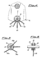
- said apparatus comprises in general a frame 10, shown partially and more particularly shown in the portion thereof where the operating tools thereof are mounted.
- Rotating drum 12 comprises two substantially circular end flanges 14 having integrally fastened thereto, in a central position and at the ends thereof, a shaft 16, which will be connected, in any way not shown, to driving means, not shown as well, comprising for instance an adjustable speed driving motor.
- rotating drum 12 includes support spindles 18, four in the embodiment shown herein, which are fastened at the ends thereof to flanges 14, in a substantially peripheral position and at equally spaced angles from each other. Therefore, in the embodiment considered herein, support spindles 18 are spaced 90 degrees apart from each other.
- each support spindle 18 there is mounted a number of tools for working against the surface to be treated, said tools, in the embodiment considered herein, comprising substantially circular brushes 20.
- Said brushes 20, which are partially shown in Figure 2 are loosely supported on spindles 18 in that, as it is shown in particular in Figure 1, bristels 22 thereof are carried by a substantially ring shaped body 24 having a diameter larger than that of spindle 18.
- brushes 20 are shown in their rest position and the actuation thereof, particularly concerning their engagement with surface 26 to be treated, is shown in Figure 3 and described in the following.
- Bristles 22 of brushes 20 will predominantly be made of metal and with a suitable shape, but it should be understood that they may be made of a different material, depending upon the material of surface 26 to be treated.
- Figures 4 to 6 there is described therein the embodimental variation of the inventive apparatus different from the one described above only concerning the particular type of tool used. Therefore, the following description will be made referring in particular to said tool, the remaining portions of the apparatus having a construction substantially identical to that of the first embodiment and, under this assumption, similar members will be shown with the same reference numbers.
- the tool used in this case is substantially comprised of a number of nails having a head 28 but a blunted tip, only some of them being shown in these Figures, only for clarity of illustration.
- FIG. 6 shows that an array of nails 28 (only one is shown in this Figure), is supported by a pair of ring shaped members 30 shrunk on spindle 18, at such a distance that they can retain nails 28 at the heads thereof.
- the distance between two ring shaped members will be kept such that nails 28, and in particular their heads may move in a substantially ring shaped cavity 32 of members 30.
- Actuation of nails 28 will be provided either as the one shown for nails 28a which, being a member substantially and relatively yieldable of the tool, move back towards spindle 18 along substantially sloping and converging directions, or, as shown for nail 28b, relatively yieldable as well, which moves back towards spindle 18 along a substantially radial path.
Landscapes
- Engineering & Computer Science (AREA)
- Mining & Mineral Resources (AREA)
- Mechanical Engineering (AREA)
- Treatments Of Macromolecular Shaped Articles (AREA)
- Polishing Bodies And Polishing Tools (AREA)
Applications Claiming Priority (2)
| Application Number | Priority Date | Filing Date | Title |
|---|---|---|---|
| IT1965990 | 1990-03-13 | ||
| IT19659A IT1239387B (it) | 1990-03-13 | 1990-03-13 | Apparecchiatura per il trattamento di superfici di media e grande ampiezza |
Publications (1)
| Publication Number | Publication Date |
|---|---|
| EP0448527A1 true EP0448527A1 (de) | 1991-09-25 |
Family
ID=11160157
Family Applications (1)
| Application Number | Title | Priority Date | Filing Date |
|---|---|---|---|
| EP91830096A Withdrawn EP0448527A1 (de) | 1990-03-13 | 1991-03-12 | Vorrichtung zum Behandeln von Oberflächen mittlerer oder grosser Breite |
Country Status (2)
| Country | Link |
|---|---|
| EP (1) | EP0448527A1 (de) |
| IT (1) | IT1239387B (de) |
Cited By (1)
| Publication number | Priority date | Publication date | Assignee | Title |
|---|---|---|---|---|
| EP4549089A4 (de) * | 2022-06-30 | 2026-05-13 | Japan Production & Sales Company Llc | Oberflächenbehandlungselement und oberflächenbehandlungssystem |
Citations (9)
| Publication number | Priority date | Publication date | Assignee | Title |
|---|---|---|---|---|
| US1929650A (en) * | 1930-12-16 | 1933-10-10 | Richard W Randall | Tube cleaner |
| FR768407A (fr) * | 1934-02-08 | 1934-08-06 | Outil pour le nettoyage et le décapage des surfaces | |
| DE736362C (de) * | 1938-06-21 | 1943-06-12 | Heinrich Max Colditz | Umlaufendes Aufrauhwerkzeug |
| US2324272A (en) * | 1941-03-28 | 1943-07-13 | Tennant Co G H | Wire brush abrading device |
| FR897277A (fr) * | 1943-08-17 | 1945-03-16 | Brosse mécanique tournante à action centrifuge | |
| DE807847C (de) * | 1948-12-28 | 1951-07-05 | Philipp Reinheimer | Aufrauhkoerper zum Rauhen von vulkanisierten Gummireifen o. dgl. |
| US2740980A (en) * | 1953-02-25 | 1956-04-10 | Charles T Asbury | Apparatus for cutting and abrading |
| US3036324A (en) * | 1958-03-17 | 1962-05-29 | Charles T Asbury | Cutting tool |
| US3754296A (en) * | 1971-12-16 | 1973-08-28 | G Talbert | Rotary flail type chipping head |
-
1990
- 1990-03-13 IT IT19659A patent/IT1239387B/it active IP Right Grant
-
1991
- 1991-03-12 EP EP91830096A patent/EP0448527A1/de not_active Withdrawn
Patent Citations (9)
| Publication number | Priority date | Publication date | Assignee | Title |
|---|---|---|---|---|
| US1929650A (en) * | 1930-12-16 | 1933-10-10 | Richard W Randall | Tube cleaner |
| FR768407A (fr) * | 1934-02-08 | 1934-08-06 | Outil pour le nettoyage et le décapage des surfaces | |
| DE736362C (de) * | 1938-06-21 | 1943-06-12 | Heinrich Max Colditz | Umlaufendes Aufrauhwerkzeug |
| US2324272A (en) * | 1941-03-28 | 1943-07-13 | Tennant Co G H | Wire brush abrading device |
| FR897277A (fr) * | 1943-08-17 | 1945-03-16 | Brosse mécanique tournante à action centrifuge | |
| DE807847C (de) * | 1948-12-28 | 1951-07-05 | Philipp Reinheimer | Aufrauhkoerper zum Rauhen von vulkanisierten Gummireifen o. dgl. |
| US2740980A (en) * | 1953-02-25 | 1956-04-10 | Charles T Asbury | Apparatus for cutting and abrading |
| US3036324A (en) * | 1958-03-17 | 1962-05-29 | Charles T Asbury | Cutting tool |
| US3754296A (en) * | 1971-12-16 | 1973-08-28 | G Talbert | Rotary flail type chipping head |
Cited By (1)
| Publication number | Priority date | Publication date | Assignee | Title |
|---|---|---|---|---|
| EP4549089A4 (de) * | 2022-06-30 | 2026-05-13 | Japan Production & Sales Company Llc | Oberflächenbehandlungselement und oberflächenbehandlungssystem |
Also Published As
| Publication number | Publication date |
|---|---|
| IT9019659A0 (it) | 1990-03-13 |
| IT9019659A1 (it) | 1991-09-13 |
| IT1239387B (it) | 1993-10-20 |
Similar Documents
| Publication | Publication Date | Title |
|---|---|---|
| KR20070093362A (ko) | 브러쉬 유닛 및 브러쉬 유닛을 이용한 재료 표면의기계가공법 | |
| US3683556A (en) | Centrifugal blasting wheel | |
| US4148110A (en) | Rotating scraping or abrading tool | |
| KR20130126599A (ko) | 브러쉬 유닛 | |
| KR20230131135A (ko) | 브러시 어셈블리 | |
| JPH03117348A (ja) | 整流子を仕上げするための方法及び装置 | |
| JP4428858B2 (ja) | 鋳鉄管の内面処理装置 | |
| US4640553A (en) | Brake system for cutters of surface cleaning cutter cage | |
| US3857135A (en) | Vehicle polishing apparatus | |
| AU2023200348A1 (en) | Brush unit | |
| US2085202A (en) | Brush | |
| CA1229986A (en) | Deburring method and apparatus | |
| US3384418A (en) | Method and device for rounding brush bristles | |
| US3695723A (en) | Abrading tool | |
| US4256510A (en) | Method of scraping corners | |
| US6244947B1 (en) | Wire brush attachment for angle grinder | |
| JPH07505579A (ja) | 回転工具 | |
| JP3613884B2 (ja) | ホーニングヘッドの砥石ドレッシング方法 | |
| SU1674788A1 (ru) | Инструмент дл зачистки поверхностей | |
| US6101694A (en) | Method for removing used elastomeric covers from rollers and a device for performing same | |
| WO2004065063A2 (en) | Rotary sanding tool | |
| EP1291133A1 (de) | Industrielle bürste | |
| JPH07484Y2 (ja) | 研削機の回転研削具 | |
| US5335976A (en) | Treatment disk of apparatus for roughening or treating surfaces | |
| AU695972B2 (en) | Wire brush attachment for angle grinder |
Legal Events
| Date | Code | Title | Description |
|---|---|---|---|
| PUAI | Public reference made under article 153(3) epc to a published international application that has entered the european phase |
Free format text: ORIGINAL CODE: 0009012 |
|
| AK | Designated contracting states |
Kind code of ref document: A1 Designated state(s): AT BE CH DE DK ES FR GB GR LI LU NL SE |
|
| STAA | Information on the status of an ep patent application or granted ep patent |
Free format text: STATUS: THE APPLICATION IS DEEMED TO BE WITHDRAWN |
|
| 18D | Application deemed to be withdrawn |
Effective date: 19920326 |