EP0448722B1 - Einrichtung zur Übervachung der Bestrahlungsdosis eines Produktes - Google Patents
Einrichtung zur Übervachung der Bestrahlungsdosis eines Produktes Download PDFInfo
- Publication number
- EP0448722B1 EP0448722B1 EP90914757A EP90914757A EP0448722B1 EP 0448722 B1 EP0448722 B1 EP 0448722B1 EP 90914757 A EP90914757 A EP 90914757A EP 90914757 A EP90914757 A EP 90914757A EP 0448722 B1 EP0448722 B1 EP 0448722B1
- Authority
- EP
- European Patent Office
- Prior art keywords
- conveyor
- dose
- barrier
- irradiation
- product
- Prior art date
- Legal status (The legal status is an assumption and is not a legal conclusion. Google has not performed a legal analysis and makes no representation as to the accuracy of the status listed.)
- Expired - Lifetime
Links
Images


Classifications
-
- G—PHYSICS
- G21—NUCLEAR PHYSICS; NUCLEAR ENGINEERING
- G21K—HANDLING OF PARTICLES OR IONISING RADIATION NOT OTHERWISE PROVIDED FOR; IRRADIATION DEVICES; GAMMA RAY OR X-RAY MICROSCOPES
- G21K5/00—Irradiation devices
-
- G—PHYSICS
- G21—NUCLEAR PHYSICS; NUCLEAR ENGINEERING
- G21K—HANDLING OF PARTICLES OR IONISING RADIATION NOT OTHERWISE PROVIDED FOR; IRRADIATION DEVICES; GAMMA RAY OR X-RAY MICROSCOPES
- G21K5/00—Irradiation devices
- G21K5/10—Irradiation devices with provision for relative movement of beam source and object to be irradiated
-
- B—PERFORMING OPERATIONS; TRANSPORTING
- B29—WORKING OF PLASTICS; WORKING OF SUBSTANCES IN A PLASTIC STATE IN GENERAL
- B29C—SHAPING OR JOINING OF PLASTICS; SHAPING OF MATERIAL IN A PLASTIC STATE, NOT OTHERWISE PROVIDED FOR; AFTER-TREATMENT OF THE SHAPED PRODUCTS, e.g. REPAIRING
- B29C71/00—After-treatment of articles without altering their shape; Apparatus therefor
- B29C71/04—After-treatment of articles without altering their shape; Apparatus therefor by wave energy or particle radiation, e.g. for curing or vulcanising preformed articles
-
- G—PHYSICS
- G21—NUCLEAR PHYSICS; NUCLEAR ENGINEERING
- G21K—HANDLING OF PARTICLES OR IONISING RADIATION NOT OTHERWISE PROVIDED FOR; IRRADIATION DEVICES; GAMMA RAY OR X-RAY MICROSCOPES
- G21K1/00—Arrangements for handling particles or ionising radiation, e.g. focusing or moderating
- G21K1/10—Scattering devices; Absorbing devices; Ionising radiation filters
-
- B—PERFORMING OPERATIONS; TRANSPORTING
- B29—WORKING OF PLASTICS; WORKING OF SUBSTANCES IN A PLASTIC STATE IN GENERAL
- B29C—SHAPING OR JOINING OF PLASTICS; SHAPING OF MATERIAL IN A PLASTIC STATE, NOT OTHERWISE PROVIDED FOR; AFTER-TREATMENT OF THE SHAPED PRODUCTS, e.g. REPAIRING
- B29C35/00—Heating, cooling or curing, e.g. crosslinking or vulcanising; Apparatus therefor
- B29C35/02—Heating or curing, e.g. crosslinking or vulcanizing during moulding, e.g. in a mould
- B29C35/08—Heating or curing, e.g. crosslinking or vulcanizing during moulding, e.g. in a mould by wave energy or particle radiation
- B29C35/0866—Heating or curing, e.g. crosslinking or vulcanizing during moulding, e.g. in a mould by wave energy or particle radiation using particle radiation
- B29C2035/0877—Heating or curing, e.g. crosslinking or vulcanizing during moulding, e.g. in a mould by wave energy or particle radiation using particle radiation using electron radiation, e.g. beta-rays
-
- B—PERFORMING OPERATIONS; TRANSPORTING
- B29—WORKING OF PLASTICS; WORKING OF SUBSTANCES IN A PLASTIC STATE IN GENERAL
- B29L—INDEXING SCHEME ASSOCIATED WITH SUBCLASS B29C, RELATING TO PARTICULAR ARTICLES
- B29L2007/00—Flat articles, e.g. films or sheets
- B29L2007/008—Wide strips, e.g. films, webs
-
- B—PERFORMING OPERATIONS; TRANSPORTING
- B29—WORKING OF PLASTICS; WORKING OF SUBSTANCES IN A PLASTIC STATE IN GENERAL
- B29L—INDEXING SCHEME ASSOCIATED WITH SUBCLASS B29C, RELATING TO PARTICULAR ARTICLES
- B29L2031/00—Other particular articles
- B29L2031/712—Containers; Packaging elements or accessories, Packages
- B29L2031/7158—Bottles
Definitions
- the present invention relates to an apparatus for controlling the dose of irradiation, designed for controlling the dose of electron rays with which a synthetic resin product is irradiated.
- the product may be a bottle or a film or its preform. Such control may eliminate the monomers contained in the product. It is also desirable to control the dose of ultraviolet or infrared rays with which such a product is irradiated for surface treatment, material treatment or sterilisation.
- the amount of electron rays with which products are irradiated should be differentiated depending on the thickness and shape of the products and other considerations.
- Such differentiation of dose of electron rays is normally realised by moving the conveyor belts at different speeds to optimise the duration of exposure to each of the products in the irradiation zone, the speed of each of the conveyor belts being appropriately selected to meet the required amount of electron rays for preforms on it.
- the number of products that can be fed to a conveyor per unit time often differs from the number of products that can be treated by electron rays per unit time.
- the number of products fed onto each of the conveyors is a function of their size and shape while the speed at which each of the conveyors is operated is a function of the dose required by the products being carried on it and there are no existing apparatuses that simultaneously satisfy these two functional requirements, resulting in too poorly fed conveyors that operate at a high speed and too heavily fed conveyors that operate at a low speed and accompanied by the problem of congestion and occasional accidents.
- an apparatus for controlling the dose of irradiation of a product comprising a first barrier body and a second barrier body, having the same configuration as the first barrier body, arranged in juxtaposition with one another, and arranged between a conveyor of the product and an irradiation device located opposite to the conveyor, the said first barrier and the said second barrier both being slidably movable along a running direction of the conveyor, characterised in that each body comprises a plurality of oblique sections arranged obliquely to the running direction of the conveyor, the relative position between the first barrier body and the second barrier body in the running direction of the conveyor being so adjustable as to enable control of the dose of irradiation reaching the product.
- Each of the first and second barrier bodies may be so constructed that it is formed with a conduit for circulation of coolant, preferably water, through an internal area of the body.
- the product can be exposed to electron rays to a maximum extent by removing the first and second barrier bodies from the electron rays irradiation zone through a sliding action.
- the dose to which the product is subjected should be limited to a given extent, it can be controlled by moving the first and second barrier bodies until the gap between the two barrier bodies meets the required distance so that the product is exposed only to those electron rays that come through the gap and hence receives the required dose.
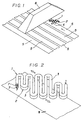
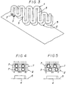
- the barrier bodies and may be placed in a completely overlapped position through a sliding action between the irradiation device and the conveyor to maximise the gap through which electron rays can pass and therefore the exposure of the product to the rays (see Figures 2 and 4).
- the first and second barrier bodies are moved relative to each other along the moving direction of the conveyor through a sliding action so that any two corresponding oblique sections of the barrier bodies that have been overlapped are now separated from each other to reduce the area of the gaps between any adjacent sections and hence to limit the exposure of the product to electron rays to a desired level.
- each of the first and second barrier bodies When each of the first and second barrier bodies are provided with a conduit for coolant to run through its entire internal area, they can be effectively cooled even if they are excessively heated by the irradiated electron rays. Since the coolant is constantly circulated through the conduit in each of the barrier bodies, any danger of the coolant emitting heat due to the air bubbles formed within it through irradiation of electron rays, is effectively eliminated.
- a first barrier body 1 and a second barrier body 2 have the same configuration, each having a plurality of oblique sections 3 arranged obliquely to the running direction of a conveyor 5.
- the first and second barrier bodies 1 and 2 are vertically juxtaposed and they each comprise a stainless steel pipe which is folded a number of times to form a zigzag route. Coolant passes through into the pipe.
- the stainless steel pipe is made of SU304 of Japanese Industrial Standards with a view to preventing rust being forming on the surface thereof under the influence of ozone generated by the electron rays.
- the angle of the oblique sections 3 relative to the moving direction of the conveyor 5 is preferably between 15 and 90 degrees, but is not limited thereto.
- the conveyor 5 includes a number of buckets for receiving a preform 4 (not shown). Each bucket carries the preform 4 therein while the preform 4 is constantly rotated so that it is evenly exposed to electron rays.
- the present invention is not limited to the case in which preforms carried by the conveyors are rotated.
- the case in which the carried preform is not rotated is included in the present invention.
- first and second barrier bodies 1 and 2 have the same configuration, but are vertically juxtaposed.
- Each barrier body comprises a rectangular shaped frame and a plurality of oblique sections obliquely arranged relative to the lateral and longitudinal members of the frame.
- the frame members and oblique sections are hollow in cross section and communicate with one another to form a complete route for circulation of coolant, for example water, that runs there through from one end of the route to the other.
- An apparatus for controlling the dose of irradiation according to the invention is applicable not only to control of the dose of electron rays to synthetic resin products but also to that of ultraviolet or infrared rays to be used for surface treatment or material treatment.
- an apparatus for controlling the dose of irradiation according to the present invention is not limited to preforms of synthetic resin bottles or films but is applicable to those of synthetic resin tubes and other forms, as well as to metal products, paper products and so on.
- an apparatus for controlling the dose of irradiation can control the dose of electron rays, ultraviolet rays, infrared rays and the like reaching the products by adjusting the gap between its first and second barrier bodies, the running speed of a conveyor carrying the products can be determined so as to match the rate of supply of products rendering it unnecessary to reduce the speed of the conveyor to maximise the dose for the products. Consequently, with an apparatus in accordance with the invention, the problems of congested are production lines and reduced line productivity are obviated.
- each of the first and second barrier bodies is provided with a conduit for circulation of coolant, they can be effectively cooled even if they are undesirably heated by electron rays, and stored heat and any bubbles of air that are formed in the coolant can be effectively moved away to eliminate any danger of storage of excessive heat within the barrier bodies. Therefore, an apparatus for controlling the dose of irradiation according to the present invention is highly durable and hence remarkably cost effective.
Landscapes
- Physics & Mathematics (AREA)
- Engineering & Computer Science (AREA)
- General Engineering & Computer Science (AREA)
- High Energy & Nuclear Physics (AREA)
- Spectroscopy & Molecular Physics (AREA)
- Treatments Of Macromolecular Shaped Articles (AREA)
- Food Preservation Except Freezing, Refrigeration, And Drying (AREA)
- Heating, Cooling, Or Curing Plastics Or The Like In General (AREA)
- Apparatus For Disinfection Or Sterilisation (AREA)
- Physical Or Chemical Processes And Apparatus (AREA)
- Measurement Of Radiation (AREA)
- Supply, Installation And Extraction Of Printed Sheets Or Plates (AREA)
- Manufacturing And Processing Devices For Dough (AREA)
- Radiation-Therapy Devices (AREA)
- Cooling, Air Intake And Gas Exhaust, And Fuel Tank Arrangements In Propulsion Units (AREA)
- Processing And Handling Of Plastics And Other Materials For Molding In General (AREA)
- Medicines Containing Material From Animals Or Micro-Organisms (AREA)
Claims (2)
- Vorrichtung zur Steuerung der Bestrahlungsdosis eines Produktes, umfassend einen ersten Barrierenkörper (1) und einen zweiten Barrierenkörper (2), welcher die gleiche Konfiguration hat, wie der erste Barrierenkörper (1), welche nebeneinander angeordnet sind, und zwischen einer Transportvorrichtung (5) des Produktes und einer Bestrahlungsvorrichtung (6), welche sich gegenüber der Transportvorrichtung (5) befindet, angeordnet, wobei die erste Barriere (1) und die zweite Barriere (2) beide gleitend entlang einer Laufrichtung der Transportvorrichtung (5) beweglich sind, dadurch gekennzeichnet, daß jeder Körper (1, 2) eine Vielzahl von schrägen Abschnitten (3) umfaßt, welche gegenüber der Laufrichtung der Transportvorrichtung (5) schräg angeordnet sind, wobei die relative Position zwischen dem ersten Barrierenkörper (1) und dem zweiten Barrierenkörper (2) in der Laufrichtung der Transportvorrichtung (5) so einstellbar ist, daß die Steuerung der das Produkt erreichenden Bestrahlungsdosis ermöglicht wird.
- Vorrichtung zur Steuerung der Bestrahlungsdosis nach Anspruch 1, dadurch gekennzeichnet, daß der erste Barrierenkörper (1) und der zweite Barrierenkörper (2) jeweils mit einem Kanal (7) zur Zirkulation eines Kühlmediums durch einen inneren Bereich des Körpers ausgebildet ist.
Applications Claiming Priority (3)
| Application Number | Priority Date | Filing Date | Title |
|---|---|---|---|
| JP1263406A JP2830880B2 (ja) | 1989-10-09 | 1989-10-09 | 照射量調節装置 |
| JP263406/89 | 1989-10-09 | ||
| PCT/JP1990/001304 WO1991005353A1 (en) | 1989-10-09 | 1990-10-09 | Illuminance controlling device |
Publications (3)
| Publication Number | Publication Date |
|---|---|
| EP0448722A1 EP0448722A1 (de) | 1991-10-02 |
| EP0448722A4 EP0448722A4 (en) | 1993-05-05 |
| EP0448722B1 true EP0448722B1 (de) | 1997-01-02 |
Family
ID=17389060
Family Applications (1)
| Application Number | Title | Priority Date | Filing Date |
|---|---|---|---|
| EP90914757A Expired - Lifetime EP0448722B1 (de) | 1989-10-09 | 1990-10-09 | Einrichtung zur Übervachung der Bestrahlungsdosis eines Produktes |
Country Status (13)
| Country | Link |
|---|---|
| US (1) | US5220174A (de) |
| EP (1) | EP0448722B1 (de) |
| JP (1) | JP2830880B2 (de) |
| KR (1) | KR0172958B1 (de) |
| CN (1) | CN1040261C (de) |
| AT (1) | ATE147188T1 (de) |
| AU (1) | AU633369B2 (de) |
| CA (1) | CA2044177C (de) |
| DE (1) | DE69029573T2 (de) |
| ES (1) | ES2098272T3 (de) |
| ID (1) | ID932B (de) |
| MY (1) | MY107268A (de) |
| WO (1) | WO1991005353A1 (de) |
Families Citing this family (4)
| Publication number | Priority date | Publication date | Assignee | Title |
|---|---|---|---|---|
| US5771270A (en) * | 1997-03-07 | 1998-06-23 | Archer; David W. | Collimator for producing an array of microbeams |
| JP5534741B2 (ja) * | 2009-08-10 | 2014-07-02 | 信越ポリマー株式会社 | 基板用保持フレームの製造方法 |
| FR2984751B1 (fr) * | 2011-12-21 | 2014-08-29 | Sidel Participations | Dispositif de decontamination par irradiation de l'interieur d'un objet |
| DE102014103833B3 (de) * | 2014-03-20 | 2015-07-09 | Bundesrepublik Deutschland, Vertreten Durch Den Bundesminister Für Wirtschaft Und Energie, Dieser Vertreten Durch Den Präsidenten Der Bundesanstalt Für Materialforschung Und -Prüfung (Bam) | Schlitzblende für Anwendungen in der Radiographie |
Family Cites Families (8)
| Publication number | Priority date | Publication date | Assignee | Title |
|---|---|---|---|---|
| DE2004050B1 (de) * | 1970-01-29 | 1971-05-13 | Werner & Pfleiderer | Vorrichtung zum Behandeln von Werkstoffen mit hochenergetischen Strahlen,beispielsweise Elektronenstrahlen |
| US3826014A (en) * | 1973-03-19 | 1974-07-30 | Sun Chemical Corp | Shutter mechanism for radiation-curing lamp |
| JPS5146697A (ja) * | 1974-10-21 | 1976-04-21 | Furukawa Electric Co Ltd | Denshisenshoshasochi |
| JPS573920A (en) * | 1980-06-04 | 1982-01-09 | Furukawa Mining Co Ltd | Pile driving and drawing machine using breaker |
| JPS5750755A (en) * | 1980-09-10 | 1982-03-25 | Hitachi Ltd | Variable slit for large current ion |
| DE3138731A1 (de) * | 1981-09-29 | 1983-04-07 | Siemens AG, 1000 Berlin und 8000 München | Ueberwachungsanordnung fuer die beschleunigungsenergie eines elektronenbeschleunigers |
| JPS61220844A (ja) * | 1985-03-27 | 1986-10-01 | Toshiba Electric Equip Corp | 紫外線照射装置 |
| EP0392031A1 (de) * | 1989-04-10 | 1990-10-17 | Siemens Aktiengesellschaft | Strahlentherapiegerät mit bewegbarer Blende |
-
1989
- 1989-10-09 JP JP1263406A patent/JP2830880B2/ja not_active Expired - Fee Related
-
1990
- 1990-10-08 US US07/688,516 patent/US5220174A/en not_active Expired - Fee Related
- 1990-10-09 DE DE69029573T patent/DE69029573T2/de not_active Expired - Fee Related
- 1990-10-09 EP EP90914757A patent/EP0448722B1/de not_active Expired - Lifetime
- 1990-10-09 WO PCT/JP1990/001304 patent/WO1991005353A1/ja not_active Ceased
- 1990-10-09 CA CA002044177A patent/CA2044177C/en not_active Expired - Fee Related
- 1990-10-09 AU AU65132/90A patent/AU633369B2/en not_active Ceased
- 1990-10-09 CN CN90109367A patent/CN1040261C/zh not_active Expired - Fee Related
- 1990-10-09 AT AT90914757T patent/ATE147188T1/de active
- 1990-10-09 KR KR1019910700580A patent/KR0172958B1/ko not_active Expired - Fee Related
- 1990-10-09 MY MYPI90001753A patent/MY107268A/en unknown
- 1990-10-09 ES ES90914757T patent/ES2098272T3/es not_active Expired - Lifetime
-
1992
- 1992-01-31 ID IDP209392A patent/ID932B/id unknown
Also Published As
| Publication number | Publication date |
|---|---|
| CA2044177C (en) | 2000-01-18 |
| KR920701986A (ko) | 1992-08-12 |
| US5220174A (en) | 1993-06-15 |
| JPH03123900A (ja) | 1991-05-27 |
| WO1991005353A1 (en) | 1991-04-18 |
| ES2098272T3 (es) | 1997-05-01 |
| JP2830880B2 (ja) | 1998-12-02 |
| CA2044177A1 (en) | 1991-04-10 |
| DE69029573D1 (de) | 1997-02-13 |
| ATE147188T1 (de) | 1997-01-15 |
| CN1051696A (zh) | 1991-05-29 |
| AU633369B2 (en) | 1993-01-28 |
| KR0172958B1 (ko) | 1999-05-01 |
| MY107268A (en) | 1995-10-31 |
| EP0448722A1 (de) | 1991-10-02 |
| AU6513290A (en) | 1991-04-28 |
| DE69029573T2 (de) | 1997-04-24 |
| ID932B (id) | 1996-09-17 |
| CN1040261C (zh) | 1998-10-14 |
| EP0448722A4 (en) | 1993-05-05 |
Similar Documents
| Publication | Publication Date | Title |
|---|---|---|
| IE20020739A1 (en) | An apparatus for the application of a curable composition to a fastener | |
| DK1115121T3 (da) | Bestrålingssystem med transportøranordning til artikelbærere | |
| KR100574256B1 (ko) | 이송시스템과 용기취입성형장치 | |
| NL8801550A (nl) | Werkwijze en installatie voor het vervaardigen van een geperforeerde kunststofbuisfoelie door inwerking van een laserstraal, geperforeerde kunststofbuisfoelie alsmede kunststofzak gevormd uit een dergelijke kunststofbuisfoelie. | |
| AU633369B2 (en) | Apparatus for controlling the dose of irradiation | |
| JPH06109899A (ja) | 電子及びその他の粒子線加速器の遮蔽のための改善された方法及び装置 | |
| US4427020A (en) | Apparatus for the overhead handling of bottles and the like | |
| CN114787821A (zh) | 用于输送产品的装置和方法 | |
| US4687612A (en) | Heat treating thermoplastic sheet materials for thermo-forming | |
| US3808301A (en) | Method for treating containers | |
| GB1566546A (en) | Apparatus for transporting articles to a machine for handling or treating the articles | |
| US3773870A (en) | Tubing irradiation process | |
| EP1502605B1 (de) | Vorrichtung und Verfahren für elektronenstrahl Bestrahlung mit verbesserten Dosierungsverhältnis | |
| GB2167032A (en) | Transfer devices | |
| GB2145963A (en) | Apparatus for heat-shrinking thermoplastic sleeves about containers | |
| US3901374A (en) | Transfer device for automatic bottle handling machines | |
| US6401907B1 (en) | Conveyor | |
| DE19704406C1 (de) | Verfahren und Vorrichtung zum Erfassen des Materialflusses von Gegenständen, insbesondere Flaschen, auf mehrbahnigen Transporteuren | |
| GB1192840A (en) | Tubing Irradiation apparatus and process | |
| US7395920B2 (en) | Method and apparatus for a conveyed product directing system | |
| SU1675361A1 (ru) | Проходной агрегат дл термической обработки изделий | |
| WO2025229091A1 (de) | Behälterbehandlungsanlage sowie verfahren zum betrieb | |
| CA1244238A (en) | Ultraviolet curing apparatus and method | |
| JPS62274030A (ja) | 熱延線材重なり密度検出手段を含む制御冷却装置およびその制御方法 | |
| NL9100846A (nl) | Transportinrichting. |
Legal Events
| Date | Code | Title | Description |
|---|---|---|---|
| PUAI | Public reference made under article 153(3) epc to a published international application that has entered the european phase |
Free format text: ORIGINAL CODE: 0009012 |
|
| 17P | Request for examination filed |
Effective date: 19910701 |
|
| AK | Designated contracting states |
Kind code of ref document: A1 Designated state(s): AT BE CH DE ES FR GB IT LI NL |
|
| A4 | Supplementary search report drawn up and despatched |
Effective date: 19930317 |
|
| AK | Designated contracting states |
Kind code of ref document: A4 Designated state(s): AT BE CH DE ES FR GB IT LI NL |
|
| 17Q | First examination report despatched |
Effective date: 19950118 |
|
| GRAG | Despatch of communication of intention to grant |
Free format text: ORIGINAL CODE: EPIDOS AGRA |
|
| RTI1 | Title (correction) | ||
| GRAH | Despatch of communication of intention to grant a patent |
Free format text: ORIGINAL CODE: EPIDOS IGRA |
|
| GRAH | Despatch of communication of intention to grant a patent |
Free format text: ORIGINAL CODE: EPIDOS IGRA |
|
| GRAA | (expected) grant |
Free format text: ORIGINAL CODE: 0009210 |
|
| AK | Designated contracting states |
Kind code of ref document: B1 Designated state(s): AT BE CH DE ES FR GB IT LI NL |
|
| REF | Corresponds to: |
Ref document number: 147188 Country of ref document: AT Date of ref document: 19970115 Kind code of ref document: T |
|
| REG | Reference to a national code |
Ref country code: CH Ref legal event code: EP |
|
| ITF | It: translation for a ep patent filed | ||
| REG | Reference to a national code |
Ref country code: CH Ref legal event code: NV Representative=s name: KIRKER & CIE SA |
|
| REF | Corresponds to: |
Ref document number: 69029573 Country of ref document: DE Date of ref document: 19970213 |
|
| ET | Fr: translation filed | ||
| REG | Reference to a national code |
Ref country code: ES Ref legal event code: FG2A Ref document number: 2098272 Country of ref document: ES Kind code of ref document: T3 |
|
| PLBE | No opposition filed within time limit |
Free format text: ORIGINAL CODE: 0009261 |
|
| STAA | Information on the status of an ep patent application or granted ep patent |
Free format text: STATUS: NO OPPOSITION FILED WITHIN TIME LIMIT |
|
| 26N | No opposition filed | ||
| PGFP | Annual fee paid to national office [announced via postgrant information from national office to epo] |
Ref country code: ES Payment date: 19991007 Year of fee payment: 10 |
|
| PG25 | Lapsed in a contracting state [announced via postgrant information from national office to epo] |
Ref country code: ES Free format text: LAPSE BECAUSE OF NON-PAYMENT OF DUE FEES Effective date: 20001010 |
|
| PGFP | Annual fee paid to national office [announced via postgrant information from national office to epo] |
Ref country code: BE Payment date: 20001018 Year of fee payment: 11 |
|
| PGFP | Annual fee paid to national office [announced via postgrant information from national office to epo] |
Ref country code: FR Payment date: 20001025 Year of fee payment: 11 |
|
| PGFP | Annual fee paid to national office [announced via postgrant information from national office to epo] |
Ref country code: NL Payment date: 20001031 Year of fee payment: 11 Ref country code: AT Payment date: 20001031 Year of fee payment: 11 |
|
| PGFP | Annual fee paid to national office [announced via postgrant information from national office to epo] |
Ref country code: CH Payment date: 20010118 Year of fee payment: 11 |
|
| PG25 | Lapsed in a contracting state [announced via postgrant information from national office to epo] |
Ref country code: AT Free format text: LAPSE BECAUSE OF NON-PAYMENT OF DUE FEES Effective date: 20011009 |
|
| PGFP | Annual fee paid to national office [announced via postgrant information from national office to epo] |
Ref country code: GB Payment date: 20011010 Year of fee payment: 12 |
|
| PGFP | Annual fee paid to national office [announced via postgrant information from national office to epo] |
Ref country code: DE Payment date: 20011022 Year of fee payment: 12 |
|
| PG25 | Lapsed in a contracting state [announced via postgrant information from national office to epo] |
Ref country code: LI Free format text: LAPSE BECAUSE OF NON-PAYMENT OF DUE FEES Effective date: 20011031 Ref country code: CH Free format text: LAPSE BECAUSE OF NON-PAYMENT OF DUE FEES Effective date: 20011031 Ref country code: BE Free format text: LAPSE BECAUSE OF NON-PAYMENT OF DUE FEES Effective date: 20011031 |
|
| REG | Reference to a national code |
Ref country code: GB Ref legal event code: IF02 |
|
| BERE | Be: lapsed |
Owner name: YOSHINO KOGYOSHO CO. LTD Effective date: 20011031 |
|
| PG25 | Lapsed in a contracting state [announced via postgrant information from national office to epo] |
Ref country code: NL Free format text: LAPSE BECAUSE OF NON-PAYMENT OF DUE FEES Effective date: 20020501 |
|
| REG | Reference to a national code |
Ref country code: CH Ref legal event code: PL |
|
| PG25 | Lapsed in a contracting state [announced via postgrant information from national office to epo] |
Ref country code: FR Free format text: LAPSE BECAUSE OF NON-PAYMENT OF DUE FEES Effective date: 20020628 |
|
| NLV4 | Nl: lapsed or anulled due to non-payment of the annual fee |
Effective date: 20020501 |
|
| REG | Reference to a national code |
Ref country code: FR Ref legal event code: ST |
|
| PG25 | Lapsed in a contracting state [announced via postgrant information from national office to epo] |
Ref country code: GB Free format text: LAPSE BECAUSE OF NON-PAYMENT OF DUE FEES Effective date: 20021009 |
|
| PG25 | Lapsed in a contracting state [announced via postgrant information from national office to epo] |
Ref country code: DE Free format text: LAPSE BECAUSE OF NON-PAYMENT OF DUE FEES Effective date: 20030501 |
|
| GBPC | Gb: european patent ceased through non-payment of renewal fee |
Effective date: 20021009 |
|
| REG | Reference to a national code |
Ref country code: ES Ref legal event code: FD2A Effective date: 20011113 |
|
| PG25 | Lapsed in a contracting state [announced via postgrant information from national office to epo] |
Ref country code: IT Free format text: LAPSE BECAUSE OF NON-PAYMENT OF DUE FEES;WARNING: LAPSES OF ITALIAN PATENTS WITH EFFECTIVE DATE BEFORE 2007 MAY HAVE OCCURRED AT ANY TIME BEFORE 2007. THE CORRECT EFFECTIVE DATE MAY BE DIFFERENT FROM THE ONE RECORDED. Effective date: 20051009 |