EP0448750B1 - Mehrstufige trockenverdichtende Vakuumpumpe und Verfahren zu ihrem Betrieb - Google Patents
Mehrstufige trockenverdichtende Vakuumpumpe und Verfahren zu ihrem Betrieb Download PDFInfo
- Publication number
- EP0448750B1 EP0448750B1 EP90105783A EP90105783A EP0448750B1 EP 0448750 B1 EP0448750 B1 EP 0448750B1 EP 90105783 A EP90105783 A EP 90105783A EP 90105783 A EP90105783 A EP 90105783A EP 0448750 B1 EP0448750 B1 EP 0448750B1
- Authority
- EP
- European Patent Office
- Prior art keywords
- vacuum pump
- reaction chamber
- inlet
- outlet
- pump according
- Prior art date
- Legal status (The legal status is an assumption and is not a legal conclusion. Google has not performed a legal analysis and makes no representation as to the accuracy of the status listed.)
- Expired - Lifetime
Links
- 238000000034 method Methods 0.000 title claims description 7
- 238000006243 chemical reaction Methods 0.000 claims description 42
- 239000007789 gas Substances 0.000 claims description 23
- 238000011282 treatment Methods 0.000 claims description 7
- 239000007787 solid Substances 0.000 claims description 5
- XEEYBQQBJWHFJM-UHFFFAOYSA-N Iron Chemical compound [Fe] XEEYBQQBJWHFJM-UHFFFAOYSA-N 0.000 claims description 4
- 210000000078 claw Anatomy 0.000 claims description 4
- 239000000126 substance Substances 0.000 claims description 4
- 238000001816 cooling Methods 0.000 claims description 3
- 230000009931 harmful effect Effects 0.000 claims description 3
- 238000010438 heat treatment Methods 0.000 claims description 3
- 230000000717 retained effect Effects 0.000 claims description 3
- HCHKCACWOHOZIP-UHFFFAOYSA-N Zinc Chemical compound [Zn] HCHKCACWOHOZIP-UHFFFAOYSA-N 0.000 claims description 2
- 229910052742 iron Inorganic materials 0.000 claims description 2
- 239000000463 material Substances 0.000 claims description 2
- 229910044991 metal oxide Inorganic materials 0.000 claims description 2
- 150000004706 metal oxides Chemical class 0.000 claims description 2
- OKTJSMMVPCPJKN-UHFFFAOYSA-N Carbon Chemical compound [C] OKTJSMMVPCPJKN-UHFFFAOYSA-N 0.000 claims 2
- 238000007906 compression Methods 0.000 claims 2
- 239000000470 constituent Substances 0.000 claims 2
- 230000001627 detrimental effect Effects 0.000 claims 2
- 229910021536 Zeolite Inorganic materials 0.000 claims 1
- PNEYBMLMFCGWSK-UHFFFAOYSA-N aluminium oxide Inorganic materials [O-2].[O-2].[O-2].[Al+3].[Al+3] PNEYBMLMFCGWSK-UHFFFAOYSA-N 0.000 claims 1
- JOHCVVJGGSABQY-UHFFFAOYSA-N carbon tetraiodide Chemical compound IC(I)(I)I JOHCVVJGGSABQY-UHFFFAOYSA-N 0.000 claims 1
- 229910052593 corundum Inorganic materials 0.000 claims 1
- HNPSIPDUKPIQMN-UHFFFAOYSA-N dioxosilane;oxo(oxoalumanyloxy)alumane Chemical compound O=[Si]=O.O=[Al]O[Al]=O HNPSIPDUKPIQMN-UHFFFAOYSA-N 0.000 claims 1
- 229910001845 yogo sapphire Inorganic materials 0.000 claims 1
- 239000010457 zeolite Substances 0.000 claims 1
- 230000015572 biosynthetic process Effects 0.000 description 3
- 230000000694 effects Effects 0.000 description 3
- 238000004519 manufacturing process Methods 0.000 description 3
- 238000005299 abrasion Methods 0.000 description 2
- QSHDDOUJBYECFT-UHFFFAOYSA-N mercury Chemical compound [Hg] QSHDDOUJBYECFT-UHFFFAOYSA-N 0.000 description 2
- 229910052753 mercury Inorganic materials 0.000 description 2
- 229910052751 metal Inorganic materials 0.000 description 2
- 239000002184 metal Substances 0.000 description 2
- 238000006386 neutralization reaction Methods 0.000 description 2
- 238000009877 rendering Methods 0.000 description 2
- 238000009489 vacuum treatment Methods 0.000 description 2
- 230000002411 adverse Effects 0.000 description 1
- 239000010953 base metal Substances 0.000 description 1
- 150000001728 carbonyl compounds Chemical class 0.000 description 1
- 230000003197 catalytic effect Effects 0.000 description 1
- 238000006555 catalytic reaction Methods 0.000 description 1
- 238000004140 cleaning Methods 0.000 description 1
- 239000003245 coal Substances 0.000 description 1
- 239000011248 coating agent Substances 0.000 description 1
- 238000000576 coating method Methods 0.000 description 1
- 238000009833 condensation Methods 0.000 description 1
- 230000005494 condensation Effects 0.000 description 1
- 238000005260 corrosion Methods 0.000 description 1
- 230000007797 corrosion Effects 0.000 description 1
- 238000005530 etching Methods 0.000 description 1
- 150000004820 halides Chemical class 0.000 description 1
- 231100001261 hazardous Toxicity 0.000 description 1
- 150000004678 hydrides Chemical class 0.000 description 1
- 239000001257 hydrogen Substances 0.000 description 1
- 229910052739 hydrogen Inorganic materials 0.000 description 1
- 229910000039 hydrogen halide Inorganic materials 0.000 description 1
- 239000012433 hydrogen halide Substances 0.000 description 1
- -1 hydrogen halides Chemical class 0.000 description 1
- 150000002736 metal compounds Chemical class 0.000 description 1
- 229910001507 metal halide Inorganic materials 0.000 description 1
- 150000005309 metal halides Chemical class 0.000 description 1
- 150000002739 metals Chemical class 0.000 description 1
- 238000011017 operating method Methods 0.000 description 1
- 150000002902 organometallic compounds Chemical class 0.000 description 1
- 238000001020 plasma etching Methods 0.000 description 1
- 238000005086 pumping Methods 0.000 description 1
- 238000000197 pyrolysis Methods 0.000 description 1
- 238000006479 redox reaction Methods 0.000 description 1
- 238000000926 separation method Methods 0.000 description 1
- 238000007086 side reaction Methods 0.000 description 1
- 238000001179 sorption measurement Methods 0.000 description 1
Images

Classifications
-
- F—MECHANICAL ENGINEERING; LIGHTING; HEATING; WEAPONS; BLASTING
- F04—POSITIVE - DISPLACEMENT MACHINES FOR LIQUIDS; PUMPS FOR LIQUIDS OR ELASTIC FLUIDS
- F04C—ROTARY-PISTON, OR OSCILLATING-PISTON, POSITIVE-DISPLACEMENT MACHINES FOR LIQUIDS; ROTARY-PISTON, OR OSCILLATING-PISTON, POSITIVE-DISPLACEMENT PUMPS
- F04C28/00—Control of, monitoring of, or safety arrangements for, pumps or pumping installations specially adapted for elastic fluids
- F04C28/28—Safety arrangements; Monitoring
-
- B—PERFORMING OPERATIONS; TRANSPORTING
- B01—PHYSICAL OR CHEMICAL PROCESSES OR APPARATUS IN GENERAL
- B01D—SEPARATION
- B01D53/00—Separation of gases or vapours; Recovering vapours of volatile solvents from gases; Chemical or biological purification of waste gases, e.g. engine exhaust gases, smoke, fumes, flue gases, aerosols
- B01D53/02—Separation of gases or vapours; Recovering vapours of volatile solvents from gases; Chemical or biological purification of waste gases, e.g. engine exhaust gases, smoke, fumes, flue gases, aerosols by adsorption, e.g. preparative gas chromatography
- B01D53/04—Separation of gases or vapours; Recovering vapours of volatile solvents from gases; Chemical or biological purification of waste gases, e.g. engine exhaust gases, smoke, fumes, flue gases, aerosols by adsorption, e.g. preparative gas chromatography with stationary adsorbents
-
- B—PERFORMING OPERATIONS; TRANSPORTING
- B01—PHYSICAL OR CHEMICAL PROCESSES OR APPARATUS IN GENERAL
- B01D—SEPARATION
- B01D53/00—Separation of gases or vapours; Recovering vapours of volatile solvents from gases; Chemical or biological purification of waste gases, e.g. engine exhaust gases, smoke, fumes, flue gases, aerosols
- B01D53/32—Separation of gases or vapours; Recovering vapours of volatile solvents from gases; Chemical or biological purification of waste gases, e.g. engine exhaust gases, smoke, fumes, flue gases, aerosols by electrical effects other than those provided for in group B01D61/00
-
- B—PERFORMING OPERATIONS; TRANSPORTING
- B01—PHYSICAL OR CHEMICAL PROCESSES OR APPARATUS IN GENERAL
- B01D—SEPARATION
- B01D53/00—Separation of gases or vapours; Recovering vapours of volatile solvents from gases; Chemical or biological purification of waste gases, e.g. engine exhaust gases, smoke, fumes, flue gases, aerosols
- B01D53/34—Chemical or biological purification of waste gases
- B01D53/46—Removing components of defined structure
- B01D53/68—Halogens or halogen compounds
-
- F—MECHANICAL ENGINEERING; LIGHTING; HEATING; WEAPONS; BLASTING
- F04—POSITIVE - DISPLACEMENT MACHINES FOR LIQUIDS; PUMPS FOR LIQUIDS OR ELASTIC FLUIDS
- F04C—ROTARY-PISTON, OR OSCILLATING-PISTON, POSITIVE-DISPLACEMENT MACHINES FOR LIQUIDS; ROTARY-PISTON, OR OSCILLATING-PISTON, POSITIVE-DISPLACEMENT PUMPS
- F04C23/00—Combinations of two or more pumps, each being of rotary-piston or oscillating-piston type, specially adapted for elastic fluids; Pumping installations specially adapted for elastic fluids; Multi-stage pumps specially adapted for elastic fluids
- F04C23/001—Combinations of two or more pumps, each being of rotary-piston or oscillating-piston type, specially adapted for elastic fluids; Pumping installations specially adapted for elastic fluids; Multi-stage pumps specially adapted for elastic fluids of similar working principle
-
- F—MECHANICAL ENGINEERING; LIGHTING; HEATING; WEAPONS; BLASTING
- F04—POSITIVE - DISPLACEMENT MACHINES FOR LIQUIDS; PUMPS FOR LIQUIDS OR ELASTIC FLUIDS
- F04C—ROTARY-PISTON, OR OSCILLATING-PISTON, POSITIVE-DISPLACEMENT MACHINES FOR LIQUIDS; ROTARY-PISTON, OR OSCILLATING-PISTON, POSITIVE-DISPLACEMENT PUMPS
- F04C29/00—Component parts, details or accessories of pumps or pumping installations, not provided for in groups F04C18/00 - F04C28/00
- F04C29/0092—Removing solid or liquid contaminants from the gas under pumping, e.g. by filtering or deposition; Purging; Scrubbing; Cleaning
-
- B—PERFORMING OPERATIONS; TRANSPORTING
- B01—PHYSICAL OR CHEMICAL PROCESSES OR APPARATUS IN GENERAL
- B01D—SEPARATION
- B01D2253/00—Adsorbents used in seperation treatment of gases and vapours
- B01D2253/10—Inorganic adsorbents
- B01D2253/102—Carbon
-
- B—PERFORMING OPERATIONS; TRANSPORTING
- B01—PHYSICAL OR CHEMICAL PROCESSES OR APPARATUS IN GENERAL
- B01D—SEPARATION
- B01D2253/00—Adsorbents used in seperation treatment of gases and vapours
- B01D2253/10—Inorganic adsorbents
- B01D2253/104—Alumina
-
- B—PERFORMING OPERATIONS; TRANSPORTING
- B01—PHYSICAL OR CHEMICAL PROCESSES OR APPARATUS IN GENERAL
- B01D—SEPARATION
- B01D2253/00—Adsorbents used in seperation treatment of gases and vapours
- B01D2253/10—Inorganic adsorbents
- B01D2253/106—Silica or silicates
- B01D2253/108—Zeolites
-
- B—PERFORMING OPERATIONS; TRANSPORTING
- B01—PHYSICAL OR CHEMICAL PROCESSES OR APPARATUS IN GENERAL
- B01D—SEPARATION
- B01D2257/00—Components to be removed
- B01D2257/20—Halogens or halogen compounds
- B01D2257/204—Inorganic halogen compounds
- B01D2257/2045—Hydrochloric acid
-
- B—PERFORMING OPERATIONS; TRANSPORTING
- B01—PHYSICAL OR CHEMICAL PROCESSES OR APPARATUS IN GENERAL
- B01D—SEPARATION
- B01D2257/00—Components to be removed
- B01D2257/20—Halogens or halogen compounds
- B01D2257/204—Inorganic halogen compounds
- B01D2257/2047—Hydrofluoric acid
-
- B—PERFORMING OPERATIONS; TRANSPORTING
- B01—PHYSICAL OR CHEMICAL PROCESSES OR APPARATUS IN GENERAL
- B01D—SEPARATION
- B01D2257/00—Components to be removed
- B01D2257/20—Halogens or halogen compounds
- B01D2257/206—Organic halogen compounds
- B01D2257/2064—Chlorine
-
- B—PERFORMING OPERATIONS; TRANSPORTING
- B01—PHYSICAL OR CHEMICAL PROCESSES OR APPARATUS IN GENERAL
- B01D—SEPARATION
- B01D2257/00—Components to be removed
- B01D2257/20—Halogens or halogen compounds
- B01D2257/206—Organic halogen compounds
- B01D2257/2066—Fluorine
-
- B—PERFORMING OPERATIONS; TRANSPORTING
- B01—PHYSICAL OR CHEMICAL PROCESSES OR APPARATUS IN GENERAL
- B01D—SEPARATION
- B01D53/00—Separation of gases or vapours; Recovering vapours of volatile solvents from gases; Chemical or biological purification of waste gases, e.g. engine exhaust gases, smoke, fumes, flue gases, aerosols
- B01D53/02—Separation of gases or vapours; Recovering vapours of volatile solvents from gases; Chemical or biological purification of waste gases, e.g. engine exhaust gases, smoke, fumes, flue gases, aerosols by adsorption, e.g. preparative gas chromatography
- B01D53/04—Separation of gases or vapours; Recovering vapours of volatile solvents from gases; Chemical or biological purification of waste gases, e.g. engine exhaust gases, smoke, fumes, flue gases, aerosols by adsorption, e.g. preparative gas chromatography with stationary adsorbents
- B01D53/0407—Constructional details of adsorbing systems
- B01D53/0446—Means for feeding or distributing gases
-
- F—MECHANICAL ENGINEERING; LIGHTING; HEATING; WEAPONS; BLASTING
- F04—POSITIVE - DISPLACEMENT MACHINES FOR LIQUIDS; PUMPS FOR LIQUIDS OR ELASTIC FLUIDS
- F04C—ROTARY-PISTON, OR OSCILLATING-PISTON, POSITIVE-DISPLACEMENT MACHINES FOR LIQUIDS; ROTARY-PISTON, OR OSCILLATING-PISTON, POSITIVE-DISPLACEMENT PUMPS
- F04C2210/00—Fluid
- F04C2210/60—Condition
- F04C2210/62—Purity
Definitions
- the invention relates to a method for operating a multi-stage, dry-compressing vacuum pump with an inlet and an outlet, in which the suctioned gases contain gaseous components which endanger the operation of the vacuum pump.
- the invention also relates to a vacuum pump suitable for carrying out this operating method.
- Multi-stage dry-compressing vacuum pumps are known from DE-OS 31 47 824 and DE-OS 32 44 099. If pumps of this or a similar type are used alone or in combination with a further vacuum pump, for example a high vacuum pump, for evacuating chambers in which etching, coating or other vacuum treatment or vacuum manufacturing processes take place, then it often happens that solids enter the pump reach. In dry-compressing vacuum pumps with small gaps, these lead to the formation of layers, so that abrasion, play depletion and thus increased wear and tear occur. This results in reduced service life for the vacuum pumps.
- the separation and formation of solids can take place due to chemical reactions of components of the gases to be pumped with one another, by reactions of gas components on the surfaces and / or by catalytic effects. In addition to such chemical reactions, solid formation can also occur as a result of changes in the state of matter as a result of an increase in pressure or cooling.
- connection channel which connects two stages of a multi-stage vacuum pump of the type concerned here, accessible from the outside in order to be able to determine and remove dirt.
- a multi-stage vacuum pump is known from EP-A-272 767, which is equipped with coolers to eliminate game consumption by thermal effects.
- the gas stream leaving a pump stage is divided. One part is compressed, another part is used to temper the housing and is then cooled.
- the present invention has for its object to provide a method for operating a vacuum pump of the type mentioned, in which the adverse effects of the play between the rotors and the housing of the vacuum pump caused by chemical reactions are avoided.
- this object is achieved in that the gases sucked out of the vacuum chamber and flowing through the vacuum pump are passed through a reaction chamber in which the components endangering the vacuum pump are chemically treated at a pressure between the suction pressure and the outlet pressure of the vacuum pump such that they lose their harmful effect or that they are retained in the reaction space after a chemical reaction.
- the present invention is based on the finding that chemical treatment of the vapors to be extracted from a vacuum chamber before the gases enter the vacuum pump (i.e. at inlet pressure) with the aim of rendering the components which are hazardous to the vacuum pump harmless is difficult to carry out.
- the required reactions take place only very slowly, unless extreme conditions such as e.g. B. very high temperatures, long residence times or highly reactive Reaction partners are created with the help of which the reactions are influenced.
- Such measures are complex and costly. They can also have negative effects on the operational safety and the pumping speed of the vacuum pump. Unwanted chemical side reactions are also not excluded.
- the vacuum pump 1 according to FIG. 1 has four stages 2 to 5.
- the rotors located within the stages are driven by a common motor 6.
- the inlet 7 of the first stage 2 of the vacuum pump 1 is connected to a component shown as block 8.
- This component 8 can be, for example, a high vacuum pump, a separator, filter, condenser or the vacuum chamber itself, in which a vacuum treatment or vacuum manufacturing process is carried out.
- the vacuum pump 1 usually pumps against atmospheric pressure.
- the individual stages 2 to 5 of the vacuum pump 1 are connected to one another via connecting lines 11, 12, 13.
- This reaction chamber 14 has the task of rendering gas components which come into the pump 1 with the sucked-in gases harmless and which can endanger the operation of the vacuum pump 1, so that Abrasions, game exhaustion, Corrosion or the like in the pump stages 4 and 5 following the reaction chamber 14 are avoided.
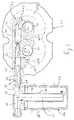
- FIG. 2 shows a partial section through a bearing plate 21 of a two-shaft vacuum pump 22, the shafts of which are designated 25 and 26.
- the bearing plate 21 serves to separate two scoops 27, 28, which are located next to or above and below the bearing plate 21.
- the contour of the scoops 27, 28 is shown in dash-dot lines.
- the shafts 25, 26 carrying the rotors pass through the end shield 21. Their direction of rotation is indicated by the arrows 35, 36.
- the passage channel 41 is provided. This connects the end-side outlet slot 43 of the inlet-side scooping space to the front-side inlet slot 44 of the outlet-side scooping space.
- Outlet 43 of the inlet-side scooping space and inlet 44 of the outlet-side scooping space are formed by arcuate recesses in the disk 16.
- the channel 41 is formed by a blind bore 45 in the end shield 21, which intersects the outlet 43 and the inlet 44 and thus establishes their connection.
- a double line system 46 in the bore 45 which in the exemplary embodiment shown here has an outer sleeve 47 and a tube 48 arranged concentrically therein .
- the annular space 49 formed by the sleeve 47 and the tube 48 is closed in the region of the end of the double line system 46 inserted into the bore 45, so that the gases emerging from the outlet 43 enter the tube 48. With the help of the tube 48, these gases are fed to the reaction chamber 14.
- the gases leaving the reaction chamber 14 reach the annular space 49 and are fed to the inlet 44 of the next stage.
- the outer sleeve 47 of the double line system has an opening 51 at the level of the inlet 44, so that the gases treated in the reaction chamber 14 can escape into the pre-vacuum-side scooping chamber.
- the reaction chamber 14 is located in an external reactor 52 which is detachably connected to the double line system 46 or to the sleeve 47.
- the reactor 52 and the sleeve 47 are equipped with flanges 53, 54.
- the reactor 52 has an inlet chamber 55 into which the inner tube 48 opens.
- the inlet space 55 is followed by a downwardly open tube section 56 which extends into the bottom region.
- the interior of this tube section 56 and the annular space between this tube section 56 and the outer housing 57 of the reactor 52 form the reactor chamber 14, in which the desired reactions of the gas components endangering the operation of the vacuum pump are to be brought about.
- An outlet chamber 58 adjoins the annular space and communicates with the annular space 49 of the double line system 46 and thus with the inlet 44 of the subsequent stage of the vacuum pump.
- the treatment of the gases flowing through the reactor space 14 can influence the temperature. This can be achieved, for example, by means of a cooling or heating coil 59 applied to the housing 57 of the reactor 52 or a heating jacket 61 provided on the central tube section (both shown in dashed lines). Other treatments (adsorption, neutralization, catalysis or the like) can be carried out with materials which are introduced into the reaction space 14.
- Hydrogen halide can be used on base metals such as As iron, can be converted to metal halide by means of redox reactions.
- the metal is expediently accommodated in the form of chips in the reaction space 14.
- metal compounds such as hydrides, halides, carbonyl compounds or organometallic compounds can be deposited metallically by means of a thermal reaction in the reactor 14.
- the reaction is favored in the presence of free metallic surfaces and is conveniently carried out at a pressure of 200 mbar.
- Neutralization of gas fractions traces of hydrogen halides sucked in, e.g. B. arise in plasma etching with CF4 when cleaning the circuit board can be neutralized by using ion exchangers or metal oxides.
Landscapes
- Engineering & Computer Science (AREA)
- Chemical & Material Sciences (AREA)
- Oil, Petroleum & Natural Gas (AREA)
- General Engineering & Computer Science (AREA)
- Analytical Chemistry (AREA)
- General Chemical & Material Sciences (AREA)
- Mechanical Engineering (AREA)
- Chemical Kinetics & Catalysis (AREA)
- Health & Medical Sciences (AREA)
- Biomedical Technology (AREA)
- Environmental & Geological Engineering (AREA)
- Applications Or Details Of Rotary Compressors (AREA)
- Treating Waste Gases (AREA)
- Chemical Vapour Deposition (AREA)
- Compressors, Vaccum Pumps And Other Relevant Systems (AREA)
Priority Applications (5)
| Application Number | Priority Date | Filing Date | Title |
|---|---|---|---|
| EP95115221A EP0692635B1 (de) | 1990-03-27 | 1990-03-27 | Mehrstufige trockenverdichtende Vakuumpumpe und Verfahren zu ihrem Betrieb |
| DE59010310T DE59010310D1 (de) | 1990-03-27 | 1990-03-27 | Mehrstufige trockenverdichtende Vakuumpumpe und Verfahren zu ihrem Betrieb |
| EP90105783A EP0448750B1 (de) | 1990-03-27 | 1990-03-27 | Mehrstufige trockenverdichtende Vakuumpumpe und Verfahren zu ihrem Betrieb |
| US07/659,587 US5131825A (en) | 1990-03-27 | 1991-02-22 | Multi-stage vacuum pump with reaction chamber between stages |
| JP3061687A JP2825673B2 (ja) | 1990-03-27 | 1991-03-26 | 乾燥圧縮型の多段式の真空ポンプの運転法および該運転法を実施するための真空ポンプ |
Applications Claiming Priority (1)
| Application Number | Priority Date | Filing Date | Title |
|---|---|---|---|
| EP90105783A EP0448750B1 (de) | 1990-03-27 | 1990-03-27 | Mehrstufige trockenverdichtende Vakuumpumpe und Verfahren zu ihrem Betrieb |
Related Child Applications (3)
| Application Number | Title | Priority Date | Filing Date |
|---|---|---|---|
| EP95115221.4 Division-Into | 1990-03-27 | ||
| EP95115221A Division-Into EP0692635B1 (de) | 1990-03-27 | 1990-03-27 | Mehrstufige trockenverdichtende Vakuumpumpe und Verfahren zu ihrem Betrieb |
| EP95115221A Division EP0692635B1 (de) | 1990-03-27 | 1990-03-27 | Mehrstufige trockenverdichtende Vakuumpumpe und Verfahren zu ihrem Betrieb |
Publications (2)
| Publication Number | Publication Date |
|---|---|
| EP0448750A1 EP0448750A1 (de) | 1991-10-02 |
| EP0448750B1 true EP0448750B1 (de) | 1996-05-01 |
Family
ID=8203820
Family Applications (2)
| Application Number | Title | Priority Date | Filing Date |
|---|---|---|---|
| EP90105783A Expired - Lifetime EP0448750B1 (de) | 1990-03-27 | 1990-03-27 | Mehrstufige trockenverdichtende Vakuumpumpe und Verfahren zu ihrem Betrieb |
| EP95115221A Expired - Lifetime EP0692635B1 (de) | 1990-03-27 | 1990-03-27 | Mehrstufige trockenverdichtende Vakuumpumpe und Verfahren zu ihrem Betrieb |
Family Applications After (1)
| Application Number | Title | Priority Date | Filing Date |
|---|---|---|---|
| EP95115221A Expired - Lifetime EP0692635B1 (de) | 1990-03-27 | 1990-03-27 | Mehrstufige trockenverdichtende Vakuumpumpe und Verfahren zu ihrem Betrieb |
Country Status (4)
| Country | Link |
|---|---|
| US (1) | US5131825A (ja) |
| EP (2) | EP0448750B1 (ja) |
| JP (1) | JP2825673B2 (ja) |
| DE (1) | DE59010310D1 (ja) |
Families Citing this family (16)
| Publication number | Priority date | Publication date | Assignee | Title |
|---|---|---|---|---|
| JP2537696B2 (ja) * | 1990-09-21 | 1996-09-25 | 株式会社荏原製作所 | 多段真空ポンプ |
| EP0541929A1 (en) * | 1991-11-12 | 1993-05-19 | SAVANT INSTRUMENTS, Inc. | Gas pumping system with liquid elimination feature |
| NL9200076A (nl) * | 1992-01-16 | 1993-08-16 | Leybold B V | Werkwijze, droge meertrapspomp en plasmascrubber voor het omvormen van reactieve gassen. |
| DE4234169A1 (de) * | 1992-10-12 | 1994-04-14 | Leybold Ag | Verfahren zum Betrieb einer trockenverdichteten Vakuumpumpe sowie für dieses Betriebsverfahren geeignete Vakuumpumpe |
| US5879552A (en) * | 1996-01-15 | 1999-03-09 | Bradfield; Michael T. | Method and apparatus for a self-purifying filter system |
| DE19623757A1 (de) | 1996-06-14 | 1997-12-18 | Bosch Gmbh Robert | Druckmittelbetätigbarer Arbeitszylinder |
| GB9902083D0 (en) * | 1999-01-29 | 1999-03-24 | Boc Group Plc | Vacuum pump systems |
| DE10110368A1 (de) * | 2001-03-03 | 2002-09-12 | Leybold Vakuum Gmbh | Vakuumpumpe mit Schöpfraum und Austritt |
| FR2863103B1 (fr) * | 2003-12-01 | 2006-07-14 | Cit Alcatel | Systeme de traitement des gaz par plasma integre dans une pompe a vide |
| EP2458218A1 (en) | 2010-11-30 | 2012-05-30 | Converteam Technology Ltd | A system for maintaining a high vacuum |
| FR2981705B1 (fr) * | 2011-10-19 | 2013-11-22 | Adixen Vacuum Products | Dispositif de pompage et de traitement des gaz |
| EP2644264A1 (de) | 2012-03-28 | 2013-10-02 | Aurotec GmbH | Druckreguliertes Mehrreaktorsystem |
| DE202012012359U1 (de) * | 2012-12-22 | 2014-03-24 | Oerlikon Leybold Vacuum Gmbh | Pumpstand zum Pumpen leichter Gase |
| DE202013003819U1 (de) * | 2013-04-24 | 2014-07-25 | Oerlikon Leybold Vacuum Gmbh | Vakuumpumpen-System |
| JP6441660B2 (ja) | 2014-03-17 | 2018-12-19 | 株式会社荏原製作所 | 除害機能付真空ポンプ |
| JP6472653B2 (ja) * | 2014-03-17 | 2019-02-20 | 株式会社荏原製作所 | 除害機能付真空ポンプ |
Family Cites Families (15)
| Publication number | Priority date | Publication date | Assignee | Title |
|---|---|---|---|---|
| US1769153A (en) * | 1928-03-07 | 1930-07-01 | Meyer William Warren | Rotary blower or pump |
| US2971691A (en) * | 1955-08-16 | 1961-02-14 | Heraeus Gmbh W C | Pumping system |
| US3535058A (en) * | 1969-01-02 | 1970-10-20 | Verbol J Devine | Method and apparatus for compressing a fluid |
| US4010016A (en) * | 1975-05-27 | 1977-03-01 | Ingersoll-Rand Company | Gas compressor |
| GB1551725A (en) * | 1975-09-06 | 1979-08-30 | Rolls Royce | Primary systems for pumps |
| GB2088957B (en) | 1980-12-05 | 1984-12-12 | Boc Ltd | Rotary positive-displacement fluidmachines |
| GB2111126A (en) | 1981-12-09 | 1983-06-29 | British Oxygen Co Ltd | Rotary positive-displacement fluid-machines |
| JPS59229072A (ja) * | 1983-06-09 | 1984-12-22 | Mitsui Toatsu Chem Inc | 天然ガス井戸用ガス圧縮機 |
| JPS61197793A (ja) * | 1985-02-26 | 1986-09-02 | Ebara Corp | 多段複葉型真空ポンプにおける冷却方法 |
| JPS62107287A (ja) * | 1985-11-01 | 1987-05-18 | Hitachi Ltd | 真空ポンプ |
| DE3627956A1 (de) * | 1986-08-18 | 1988-03-03 | Wankel Gmbh | Exzenterwelle einer rotationskolbenbrennkraftmaschine |
| JPH0733834B2 (ja) * | 1986-12-18 | 1995-04-12 | 株式会社宇野澤組鐵工所 | ロータ内蔵ハウジングの外周温度が安定化された内部分流逆流冷却多段式の三葉式真空ポンプ |
| JPH01247787A (ja) * | 1988-02-29 | 1989-10-03 | Leybold Ag | 多段真空ポンプ |
| GB8809621D0 (en) * | 1988-04-22 | 1988-05-25 | Boc Group Plc | Dry pump with closed loop filter |
| FR2642479B1 (fr) * | 1989-02-02 | 1994-03-18 | Alcatel Cit | Pompe a vide du type roots, multietagee |
-
1990
- 1990-03-27 DE DE59010310T patent/DE59010310D1/de not_active Expired - Fee Related
- 1990-03-27 EP EP90105783A patent/EP0448750B1/de not_active Expired - Lifetime
- 1990-03-27 EP EP95115221A patent/EP0692635B1/de not_active Expired - Lifetime
-
1991
- 1991-02-22 US US07/659,587 patent/US5131825A/en not_active Expired - Fee Related
- 1991-03-26 JP JP3061687A patent/JP2825673B2/ja not_active Expired - Fee Related
Also Published As
| Publication number | Publication date |
|---|---|
| US5131825A (en) | 1992-07-21 |
| EP0448750A1 (de) | 1991-10-02 |
| EP0692635A2 (de) | 1996-01-17 |
| EP0692635A3 (de) | 1997-04-02 |
| EP0692635B1 (de) | 1999-09-08 |
| JPH0579488A (ja) | 1993-03-30 |
| DE59010310D1 (de) | 1996-06-05 |
| JP2825673B2 (ja) | 1998-11-18 |
Similar Documents
| Publication | Publication Date | Title |
|---|---|---|
| EP0448750B1 (de) | Mehrstufige trockenverdichtende Vakuumpumpe und Verfahren zu ihrem Betrieb | |
| DE3879423T2 (de) | Schraubenkolben-vakuumpumpe. | |
| DE69737315T2 (de) | Auslasssystem | |
| DE68903355T2 (de) | Vakuumpumpen. | |
| DE69113929T2 (de) | System für die Zufuhr reaktiver Gase von einer Gasquelle zu einer Vorrichtung. | |
| EP0964999B1 (de) | Vakuumpumpe | |
| DE3333530C2 (de) | Vakuumrückhalteeinrichtung für ein Dampfkraftwerk | |
| DE60113894T2 (de) | Dichtungsanordnungen | |
| WO2008022916A1 (de) | Verfahren zur abreaktion selbstentzündlicher stäube in einer vakuumpumpvorrichtung | |
| DE3540445A1 (de) | Zweizylindriger rotationsverdichter | |
| EP0167914B1 (de) | Anlage zur Metallpulver-Herstellung durch Edelgas- oder Stickstoffverdüsung | |
| EP1065385A2 (de) | Verfahren zum Betrieb einer Mehrkammer-Vakuumanlage | |
| WO1999024136A1 (de) | Ausfrieren einer gaskomponente aus einem gasgemisch | |
| EP0401399B1 (de) | Zwei- oder mehrstufige Hochvakuumpumpe | |
| DE4232119A1 (de) | Regelung einer Wälzkolbenpumpe | |
| DE10008609C1 (de) | Filter und Verfahren zur Abtrennung von Ölspuren aus Druckgasen | |
| DE69712387T2 (de) | Abgasanlage in einem Ionenimplantierungssystem | |
| JP5420543B2 (ja) | 多段圧縮システムにおける圧縮機の使用不能化汚損に耐える方法および装置 | |
| EP2054129B1 (en) | Improved method and apparatus for protective atmosphere recycling | |
| DE3032967A1 (de) | Molekularpumpe, insbesondere turbomolekularpumpe, und damit ausgeruestetes pumpsystem | |
| EP0649505B1 (de) | Wellendichtung | |
| DE2832726C2 (ja) | ||
| EP0739650B1 (de) | Evakuierungssystem mit Abgasreiningung und Betriebsverfahren hierfür | |
| DE19858883A1 (de) | Verfahren und Vorrichtung zur Entstaubung von Räumen mit hoher Staubbelastung | |
| DE102009019720A1 (de) | Ölfilterstation mit Ölfilter für Kältemaschinen oder -anlagen |
Legal Events
| Date | Code | Title | Description |
|---|---|---|---|
| PUAI | Public reference made under article 153(3) epc to a published international application that has entered the european phase |
Free format text: ORIGINAL CODE: 0009012 |
|
| AK | Designated contracting states |
Kind code of ref document: A1 Designated state(s): CH DE FR GB IT LI |
|
| 17P | Request for examination filed |
Effective date: 19920331 |
|
| 17Q | First examination report despatched |
Effective date: 19921127 |
|
| GRAA | (expected) grant |
Free format text: ORIGINAL CODE: 0009210 |
|
| AK | Designated contracting states |
Kind code of ref document: B1 Designated state(s): CH DE FR GB IT LI |
|
| REF | Corresponds to: |
Ref document number: 59010310 Country of ref document: DE Date of ref document: 19960605 |
|
| ITF | It: translation for a ep patent filed | ||
| REG | Reference to a national code |
Ref country code: CH Ref legal event code: NV Representative=s name: ISLER & PEDRAZZINI AG |
|
| GBT | Gb: translation of ep patent filed (gb section 77(6)(a)/1977) |
Effective date: 19960729 |
|
| ET | Fr: translation filed | ||
| RAP2 | Party data changed (patent owner data changed or rights of a patent transferred) |
Owner name: BALZERS UND LEYBOLD DEUTSCHLAND HOLDING AKTIENGESE |
|
| PLBQ | Unpublished change to opponent data |
Free format text: ORIGINAL CODE: EPIDOS OPPO |
|
| PLBI | Opposition filed |
Free format text: ORIGINAL CODE: 0009260 |
|
| PGFP | Annual fee paid to national office [announced via postgrant information from national office to epo] |
Ref country code: CH Payment date: 19970228 Year of fee payment: 8 |
|
| PLBF | Reply of patent proprietor to notice(s) of opposition |
Free format text: ORIGINAL CODE: EPIDOS OBSO |
|
| 26 | Opposition filed |
Opponent name: THE BOC GROUP PLC Effective date: 19970117 |
|
| PLBF | Reply of patent proprietor to notice(s) of opposition |
Free format text: ORIGINAL CODE: EPIDOS OBSO |
|
| PLBF | Reply of patent proprietor to notice(s) of opposition |
Free format text: ORIGINAL CODE: EPIDOS OBSO |
|
| PG25 | Lapsed in a contracting state [announced via postgrant information from national office to epo] |
Ref country code: LI Free format text: LAPSE BECAUSE OF NON-PAYMENT OF DUE FEES Effective date: 19980331 Ref country code: CH Free format text: LAPSE BECAUSE OF NON-PAYMENT OF DUE FEES Effective date: 19980331 |
|
| REG | Reference to a national code |
Ref country code: CH Ref legal event code: PL |
|
| PLBO | Opposition rejected |
Free format text: ORIGINAL CODE: EPIDOS REJO |
|
| APAC | Appeal dossier modified |
Free format text: ORIGINAL CODE: EPIDOS NOAPO |
|
| APAE | Appeal reference modified |
Free format text: ORIGINAL CODE: EPIDOS REFNO |
|
| APAC | Appeal dossier modified |
Free format text: ORIGINAL CODE: EPIDOS NOAPO |
|
| APAC | Appeal dossier modified |
Free format text: ORIGINAL CODE: EPIDOS NOAPO |
|
| PLBN | Opposition rejected |
Free format text: ORIGINAL CODE: 0009273 |
|
| STAA | Information on the status of an ep patent application or granted ep patent |
Free format text: STATUS: OPPOSITION REJECTED |
|
| 27O | Opposition rejected |
Effective date: 20010410 |
|
| REG | Reference to a national code |
Ref country code: GB Ref legal event code: IF02 |
|
| PGFP | Annual fee paid to national office [announced via postgrant information from national office to epo] |
Ref country code: FR Payment date: 20030211 Year of fee payment: 14 |
|
| PGFP | Annual fee paid to national office [announced via postgrant information from national office to epo] |
Ref country code: GB Payment date: 20030213 Year of fee payment: 14 |
|
| PGFP | Annual fee paid to national office [announced via postgrant information from national office to epo] |
Ref country code: DE Payment date: 20030225 Year of fee payment: 14 |
|
| PG25 | Lapsed in a contracting state [announced via postgrant information from national office to epo] |
Ref country code: GB Free format text: LAPSE BECAUSE OF NON-PAYMENT OF DUE FEES Effective date: 20040327 |
|
| PG25 | Lapsed in a contracting state [announced via postgrant information from national office to epo] |
Ref country code: DE Free format text: LAPSE BECAUSE OF NON-PAYMENT OF DUE FEES Effective date: 20041001 |
|
| GBPC | Gb: european patent ceased through non-payment of renewal fee |
Effective date: 20040327 |
|
| PG25 | Lapsed in a contracting state [announced via postgrant information from national office to epo] |
Ref country code: FR Free format text: LAPSE BECAUSE OF NON-PAYMENT OF DUE FEES Effective date: 20041130 |
|
| REG | Reference to a national code |
Ref country code: FR Ref legal event code: ST |
|
| PG25 | Lapsed in a contracting state [announced via postgrant information from national office to epo] |
Ref country code: IT Free format text: LAPSE BECAUSE OF NON-PAYMENT OF DUE FEES Effective date: 20050327 |
|
| APAH | Appeal reference modified |
Free format text: ORIGINAL CODE: EPIDOSCREFNO |