EP0448788A1 - Dispositif d'accouplement rapide pour excavateur - Google Patents
Dispositif d'accouplement rapide pour excavateur Download PDFInfo
- Publication number
- EP0448788A1 EP0448788A1 EP90122462A EP90122462A EP0448788A1 EP 0448788 A1 EP0448788 A1 EP 0448788A1 EP 90122462 A EP90122462 A EP 90122462A EP 90122462 A EP90122462 A EP 90122462A EP 0448788 A1 EP0448788 A1 EP 0448788A1
- Authority
- EP
- European Patent Office
- Prior art keywords
- pistons
- adapter
- pressure
- locking
- housing
- Prior art date
- Legal status (The legal status is an assumption and is not a legal conclusion. Google has not performed a legal analysis and makes no representation as to the accuracy of the status listed.)
- Granted
Links
Images




Classifications
-
- E—FIXED CONSTRUCTIONS
- E02—HYDRAULIC ENGINEERING; FOUNDATIONS; SOIL SHIFTING
- E02F—DREDGING; SOIL-SHIFTING
- E02F3/00—Dredgers; Soil-shifting machines
- E02F3/04—Dredgers; Soil-shifting machines mechanically-driven
- E02F3/28—Dredgers; Soil-shifting machines mechanically-driven with digging tools mounted on a dipper- or bucket-arm, i.e. there is either one arm or a pair of arms, e.g. dippers, buckets
- E02F3/36—Component parts
- E02F3/3604—Devices to connect tools to arms, booms or the like
- E02F3/3609—Devices to connect tools to arms, booms or the like of the quick acting type, e.g. controlled from the operator seat
- E02F3/3627—Devices to connect tools to arms, booms or the like of the quick acting type, e.g. controlled from the operator seat with a hook and a longitudinal locking element
-
- E—FIXED CONSTRUCTIONS
- E02—HYDRAULIC ENGINEERING; FOUNDATIONS; SOIL SHIFTING
- E02F—DREDGING; SOIL-SHIFTING
- E02F3/00—Dredgers; Soil-shifting machines
- E02F3/04—Dredgers; Soil-shifting machines mechanically-driven
- E02F3/28—Dredgers; Soil-shifting machines mechanically-driven with digging tools mounted on a dipper- or bucket-arm, i.e. there is either one arm or a pair of arms, e.g. dippers, buckets
- E02F3/36—Component parts
- E02F3/3604—Devices to connect tools to arms, booms or the like
- E02F3/3609—Devices to connect tools to arms, booms or the like of the quick acting type, e.g. controlled from the operator seat
- E02F3/3631—Devices to connect tools to arms, booms or the like of the quick acting type, e.g. controlled from the operator seat with a hook and a transversal locking element
-
- E—FIXED CONSTRUCTIONS
- E02—HYDRAULIC ENGINEERING; FOUNDATIONS; SOIL SHIFTING
- E02F—DREDGING; SOIL-SHIFTING
- E02F3/00—Dredgers; Soil-shifting machines
- E02F3/04—Dredgers; Soil-shifting machines mechanically-driven
- E02F3/28—Dredgers; Soil-shifting machines mechanically-driven with digging tools mounted on a dipper- or bucket-arm, i.e. there is either one arm or a pair of arms, e.g. dippers, buckets
- E02F3/36—Component parts
- E02F3/3604—Devices to connect tools to arms, booms or the like
- E02F3/3609—Devices to connect tools to arms, booms or the like of the quick acting type, e.g. controlled from the operator seat
- E02F3/3663—Devices to connect tools to arms, booms or the like of the quick acting type, e.g. controlled from the operator seat hydraulically-operated
Definitions
- the invention relates to a quick-change device according to the preamble of claim 1.
- a quick coupling for connecting an implement to a shovel loader which comprises a pair of bolts which can be brought into or out of engagement with holes in the implement.
- the bolts are actuated via linkage and bellcrank, which are connected to a compressed air cylinder.
- Such an arrangement requires a relatively large amount of space and the forces to be used to adjust the bolts are relatively high.
- the object of the invention is to provide a quick-change device which can be accommodated as a structural unit to save space on the articulated arm, has a stable structure and ensures a reliable connection between the implement and the articulated arm.
- the main advantages achieved with the invention are that the locking bolts are in an interlocking position by an interposed single compression spring and the locking bolts or the pistons of the locking bolts are pressurized accordingly only for adjustment to a rest position (unlocking position). This ensures that the system is solely under the tension of the compression spring in the locking position and thus this position is not endangered if the pressure circuit fails.
- the locking elements consisting of coaxially arranged pistons with locking bolts in a cylindrical housing, can be accommodated in a space-saving manner in an adapter and can be dimensioned according to the requirements with regard to the absorption of forces and moments.
- the hydraulic control circuit is designed so that the pistons move back against the tension of the compression spring can take place.
- the pistons could also be pressurized in the effective direction of the compression spring.
- a unit consisting of a pair of pistons with two locking pins or two pairs of pistons with four locking pins can be used.
- the pistons are adjusted via an actuatable multi-way valve of the control unit, which can be adjusted manually or electrically using a switch.
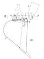
- the implement to be connected to the articulated arm is hung on the adapter, for which purpose this comprises a hook which positively engages around a cam of the implement.
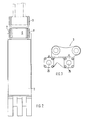
- a quick-change device 1 for an implement, such as for a backhoe 2 is accommodated in an adapter 3, which is connected to a coupling rod 4 and an articulated arm 5.
- the locking elements 6 are fastened in the adapter 3, these being arranged between the legs 7 and 8 of the bucket 2 for holding.
- the locking element 6 comprises in a cylindrical housing 9 coaxially arranged pistons 10 and 11 with locking bolts 12 and 13 formed at the ends. Between the two pistons 10 and 11 a compression spring 14 is arranged which seeks to move the pistons apart in the arrow directions 16.
- Such a locking element 6 is shown in more detail in FIG. 4, with the locking bolt 12 in a retracted rest position R and the further locking bolt 13 in an extended working position A for the sake of simplicity in a drawing.
- the locking bolts 12 and 13 together always have the same position A or R.
- the pistons 10 and 11 are connected to a hydraulic pressure circuit of a control unit 15 in such a way that the pistons can be displaced from the working position A into the rest position R against the direction of the arrow 16.
- the pistons 10 and 11 have a pressure chamber 17 between the locking bolts 12 and 13 and the housing 9, into each of which a pressure line 18, 18a opens.
- This pressure chamber 17 is delimited on the one hand by a guide sleeve 19 and on the other hand by a pressure flange 20 of the respective piston.
- the compression spring 14 is supported at the end in blind bores 21 and 22 of the pistons 10 and 11. It penetrates a central transverse wall 23 on which the pressure flanges 20, 20a of the pistons 10 and 11 are supported in the rest position R.
- FIG. 8 a first possible hydraulic circuit diagram for the control of the pistons 10 and 11 in the rest position R is shown schematically.
- This control unit 15 essentially comprises a line 30 guided by a pump 28 via a multi-way valve 29, from which lines 18 and 18a branch to the pressure chambers 17 of the pistons 10 and 11.
- FIG. 15a A second possible hydraulic circuit diagram for the control of the pistons 10 and 11 in the rest position R and for support in the working position A is shown schematically in FIG.
- the control unit 15a comprises two outgoing pressure lines 30 and 30a from the multi-way valve 29a.
- the first line 30 has lines 18 and 18a branching off to the pressure spaces 17.
- the second line 30a has a branching line 31 which leads into a space 33 between the pistons 10 and 11 and supports a movement of the pistons into a working position A, i.e. the pistons are moved in the effective direction of the spring 14.
- the recess in the connecting rib in the adapter 3 (Fig. 3) between the two bores 25 is designed so that it enables a pre-fixing during the "coupling process" as a counterpart to the stiffening profile on the bucket 2.
Landscapes
- Engineering & Computer Science (AREA)
- Mechanical Engineering (AREA)
- Mining & Mineral Resources (AREA)
- Civil Engineering (AREA)
- General Engineering & Computer Science (AREA)
- Structural Engineering (AREA)
- Earth Drilling (AREA)
- Operation Control Of Excavators (AREA)
- Shovels (AREA)
- Lubricants (AREA)
- Manipulator (AREA)
Applications Claiming Priority (2)
| Application Number | Priority Date | Filing Date | Title |
|---|---|---|---|
| DE4010224A DE4010224C2 (de) | 1990-03-30 | 1990-03-30 | Schnellwechselvorrichtung |
| DE4010224 | 1990-03-30 |
Publications (2)
| Publication Number | Publication Date |
|---|---|
| EP0448788A1 true EP0448788A1 (fr) | 1991-10-02 |
| EP0448788B1 EP0448788B1 (fr) | 1994-11-09 |
Family
ID=6403398
Family Applications (1)
| Application Number | Title | Priority Date | Filing Date |
|---|---|---|---|
| EP90122462A Expired - Lifetime EP0448788B1 (fr) | 1990-03-30 | 1990-11-26 | Dispositif d'accouplement rapide pour excavateur |
Country Status (6)
| Country | Link |
|---|---|
| US (1) | US5125788A (fr) |
| EP (1) | EP0448788B1 (fr) |
| JP (1) | JPH04222724A (fr) |
| AT (1) | ATE114010T1 (fr) |
| DE (2) | DE4010224C2 (fr) |
| NO (1) | NO302249B1 (fr) |
Cited By (7)
| Publication number | Priority date | Publication date | Assignee | Title |
|---|---|---|---|---|
| EP0615023A1 (fr) * | 1993-03-10 | 1994-09-14 | Jean-Marie Gérard René Koehl | Dispositif d'assemblage en rotation d'un bras ou analogue avec et entre deux branches d'une pièce en forme de fourche |
| EP1057941A3 (fr) * | 1999-05-11 | 2001-01-03 | Daemo Engineering Co., Ltd. | Agencement d'accouplement pour fixer de maniere liberable un dispositif d'excavation a une excavatrice |
| DE19963691C2 (de) * | 1999-03-02 | 2003-02-27 | Liebherr Hydraulikbagger | Kupplung zum pendelnden Anhängen eines Werkzeugs an den Stiel eines Baggers oder eine andere Handhabungseinrichtung |
| EP1672126A3 (fr) * | 2004-12-14 | 2007-06-06 | PMI Padana Macchine Industriali S.p.A. | Dispositif hydraulique et procédé pour l'insertion et pour l'extraction de broches dans des flèches jointes de machines de construction. |
| FR2900170A1 (fr) * | 2006-04-21 | 2007-10-26 | Innovation Equipement Sarl | Dispositif d'accouplement hydraulique d'un godet au bout d'un bras de pelleteuse par verrouillage, deverrouillage lateral |
| FR3019197A1 (fr) * | 2014-03-26 | 2015-10-02 | Morin | Systeme d’engagement d’un ensemble d’attache rapide |
| CN115262670A (zh) * | 2022-07-14 | 2022-11-01 | 宁波吉威熔模铸造有限公司 | 一种便于装配的工程机械铲斗连接组件 |
Families Citing this family (31)
| Publication number | Priority date | Publication date | Assignee | Title |
|---|---|---|---|---|
| DE4223734C2 (de) * | 1992-07-18 | 1996-04-18 | Orenstein & Koppel Ag | Schnellwechselvorrichtung |
| US5486084A (en) * | 1993-06-07 | 1996-01-23 | Raymond F. Pitman | Multiple purpose material handling and working apparatus |
| DE4408386C2 (de) * | 1994-03-12 | 1996-07-04 | Orenstein & Koppel Ag | Hydraulisch betätigte Verriegelungsvorrichtung für Schnellwechsler an Bau- und Arbeitsmaschinen |
| DE4417401A1 (de) * | 1994-05-18 | 1995-11-30 | Thomas Dipl Ing Ostermeyer | Geräteträger |
| US5634735A (en) * | 1995-06-07 | 1997-06-03 | Wain-Roy, Inc. | Tool coupler |
| SE9701887D0 (sv) | 1997-05-21 | 1997-05-21 | Accima Ab | Anordning för lösbar sammankoppling av ett arbetsredskap och en grävmaskins manöverarm |
| DE19806057C2 (de) * | 1998-02-13 | 2002-11-28 | Franz Wimmer | Baumaschinenadapter |
| NZ519487A (en) * | 1999-05-15 | 2004-06-25 | Ward Attachments Ltd A | Connection apparatus |
| US7975944B2 (en) * | 1999-10-15 | 2011-07-12 | John R. Ramun | Modular system for connecting attachments to a construction machine |
| US6994284B1 (en) * | 1999-10-15 | 2006-02-07 | Ramun John R | Multiple tool attachment system |
| US6776571B2 (en) * | 2000-10-12 | 2004-08-17 | James M. Lemieux | Fork attachment for backhoe |
| KR100430064B1 (ko) * | 2001-05-18 | 2004-05-03 | 한국기계연구원 | 굴삭기용 퀵 커플러 |
| JP2005504198A (ja) * | 2001-09-26 | 2005-02-10 | ハンウー ティーエヌシー コーポレーション | 重機用アタッチメントカップリング装置 |
| DE20215843U1 (de) | 2002-10-15 | 2003-01-16 | Rammax Maschinenbau GmbH, 72555 Metzingen | Bodenverdichtungsvorrichtung |
| JP4867371B2 (ja) * | 2006-02-01 | 2012-02-01 | コベルコ建機株式会社 | ピン連結装置 |
| US7690880B2 (en) * | 2006-04-25 | 2010-04-06 | Clark Equipment Company | Locking device for hydraulic attachment interface |
| US7984575B2 (en) * | 2007-07-05 | 2011-07-26 | Caterpillar Inc. | Quick coupler assembly |
| JP4912280B2 (ja) * | 2007-11-21 | 2012-04-11 | 株式会社室戸鉄工所 | アタッチメントカプラ |
| CA2651295A1 (fr) * | 2009-01-27 | 2010-07-27 | Nye Manufacturing Ltd. | Dispositif d'accouplement permettant de raccorder un godet ou un outil a une fleche |
| CA2829379A1 (fr) | 2011-03-10 | 2012-09-13 | Clark Equipment Company | Systeme de couplage d'outil pour machine electrique |
| US8974137B2 (en) | 2011-12-22 | 2015-03-10 | Caterpillar Inc. | Quick coupler |
| US9217235B2 (en) | 2012-05-30 | 2015-12-22 | Caterpillar Inc. | Tool coupler system having multiple pressure sources |
| US8684623B2 (en) | 2012-05-30 | 2014-04-01 | Caterpillar Inc. | Tool coupler having anti-release mechanism |
| US8869437B2 (en) | 2012-05-30 | 2014-10-28 | Caterpillar Inc. | Quick coupler |
| AT513332A1 (de) * | 2012-08-31 | 2014-03-15 | Wacker Neuson Linz Gmbh | Vorrichtung zum Kuppeln von einem Trägergerät und einem Werkzeug zugeordneten Medienleitungen |
| US9228314B2 (en) | 2013-05-08 | 2016-01-05 | Caterpillar Inc. | Quick coupler hydraulic control system |
| GB2544746A (en) * | 2015-11-24 | 2017-05-31 | Caterpillar Work Tools Bv | Apparatus and method for assembling work tool to a machine |
| US11805738B2 (en) | 2020-04-24 | 2023-11-07 | Paul E. Schmelz | Sod roller terminal attachment for excavator |
| US11952738B2 (en) | 2020-09-18 | 2024-04-09 | Great Plains Manufacturing, Inc. | Attachment coupler |
| KR102527573B1 (ko) * | 2021-01-29 | 2023-05-11 | 주식회사 이건 | 굴삭기용 코어 드릴 시스템 |
| US12449000B2 (en) * | 2021-11-19 | 2025-10-21 | Caterpillar Inc. | Compact actuated shear pin |
Citations (4)
| Publication number | Priority date | Publication date | Assignee | Title |
|---|---|---|---|---|
| FR2304726A1 (fr) * | 1975-03-18 | 1976-10-15 | Liebherr Hydraulikbagger | Appareil hydraulique de travaux publics |
| GB2132584A (en) * | 1982-12-24 | 1984-07-11 | Dobson Park Ind | Releasable connection device |
| EP0273828A1 (fr) * | 1986-12-26 | 1988-07-06 | Ardennes Equipment S.A. | Dispositif d'attache rapide pour équipements d'engins de génie civil et de manutention |
| DE9001617U1 (de) * | 1990-02-12 | 1990-04-19 | Fritzel, Walter, 6366 Wölfersheim | Löffelbagger |
Family Cites Families (11)
| Publication number | Priority date | Publication date | Assignee | Title |
|---|---|---|---|---|
| US2267644A (en) * | 1937-07-01 | 1941-12-23 | Hydraulic Press Corp Inc | Hydraulic machine circuit |
| US3033171A (en) * | 1960-09-07 | 1962-05-08 | Sperry Rand Corp | Interlocking means for hydraulic servomotor systems |
| DE1784323A1 (de) * | 1968-07-27 | 1971-08-19 | Carl Kaelble Gmbh Motoren U Ma | Schnellwechselvorrichtung fuer Schaufellader |
| GB1289602A (fr) * | 1970-04-27 | 1972-09-20 | ||
| US3934738A (en) * | 1974-04-01 | 1976-01-27 | Wain-Roy, Inc. | Tool connecting |
| SE399866B (sv) * | 1975-09-12 | 1978-03-06 | Renholmens Mek Verkstad Ab | Snabbkopplingsanordning for automatisk hopkoppling av ett av en lastmaskin eller annan redskapsberare uppburet redskapsfeste med ett arbetsredskap |
| US4373852A (en) * | 1981-07-06 | 1983-02-15 | J. I. Case Company | Quick coupling and release mechanism for buckets |
| DE8237194U1 (de) * | 1982-01-13 | 1984-02-02 | Kramer-Werke GmbH, 7770 Überlingen | Schaufellader mit einer ladeschaufelanordnung fuer die wahlweise verschwenkung vorwaerts oder seitwaerts |
| SE458693B (sv) * | 1982-11-19 | 1989-04-24 | Lidkoeping Svets & Maskinprod | Anordning foer loesbar sammankoppling av ett arbetsredskap och en graevmaskins manoeverarm |
| DE8420678U1 (de) * | 1984-07-11 | 1984-10-11 | Krupp Mak Maschinenbau Gmbh, 2300 Kiel | Verriegelungs- und absetzvorrichtung fuer arbeitsgeraete |
| DE3808313A1 (de) * | 1988-03-12 | 1989-09-28 | Kramer Werke Gmbh | Arbeitsfahrzeug, insbesondere schaufellader |
-
1990
- 1990-03-30 DE DE4010224A patent/DE4010224C2/de not_active Expired - Fee Related
- 1990-11-26 AT AT90122462T patent/ATE114010T1/de not_active IP Right Cessation
- 1990-11-26 EP EP90122462A patent/EP0448788B1/fr not_active Expired - Lifetime
- 1990-11-26 DE DE59007696T patent/DE59007696D1/de not_active Expired - Fee Related
-
1991
- 1991-03-25 US US07/676,268 patent/US5125788A/en not_active Expired - Fee Related
- 1991-03-27 NO NO911268A patent/NO302249B1/no not_active IP Right Cessation
- 1991-03-27 JP JP3063329A patent/JPH04222724A/ja active Pending
Patent Citations (4)
| Publication number | Priority date | Publication date | Assignee | Title |
|---|---|---|---|---|
| FR2304726A1 (fr) * | 1975-03-18 | 1976-10-15 | Liebherr Hydraulikbagger | Appareil hydraulique de travaux publics |
| GB2132584A (en) * | 1982-12-24 | 1984-07-11 | Dobson Park Ind | Releasable connection device |
| EP0273828A1 (fr) * | 1986-12-26 | 1988-07-06 | Ardennes Equipment S.A. | Dispositif d'attache rapide pour équipements d'engins de génie civil et de manutention |
| DE9001617U1 (de) * | 1990-02-12 | 1990-04-19 | Fritzel, Walter, 6366 Wölfersheim | Löffelbagger |
Cited By (8)
| Publication number | Priority date | Publication date | Assignee | Title |
|---|---|---|---|---|
| EP0615023A1 (fr) * | 1993-03-10 | 1994-09-14 | Jean-Marie Gérard René Koehl | Dispositif d'assemblage en rotation d'un bras ou analogue avec et entre deux branches d'une pièce en forme de fourche |
| FR2702526A1 (fr) * | 1993-03-10 | 1994-09-16 | Koehl Jean Marie Gerard Rene | Dispositif d'assemblage en rotation d'un bras ou analogue avec et entre deux branches d'une pièce en forme de fourche. |
| DE19963691C2 (de) * | 1999-03-02 | 2003-02-27 | Liebherr Hydraulikbagger | Kupplung zum pendelnden Anhängen eines Werkzeugs an den Stiel eines Baggers oder eine andere Handhabungseinrichtung |
| EP1057941A3 (fr) * | 1999-05-11 | 2001-01-03 | Daemo Engineering Co., Ltd. | Agencement d'accouplement pour fixer de maniere liberable un dispositif d'excavation a une excavatrice |
| EP1672126A3 (fr) * | 2004-12-14 | 2007-06-06 | PMI Padana Macchine Industriali S.p.A. | Dispositif hydraulique et procédé pour l'insertion et pour l'extraction de broches dans des flèches jointes de machines de construction. |
| FR2900170A1 (fr) * | 2006-04-21 | 2007-10-26 | Innovation Equipement Sarl | Dispositif d'accouplement hydraulique d'un godet au bout d'un bras de pelleteuse par verrouillage, deverrouillage lateral |
| FR3019197A1 (fr) * | 2014-03-26 | 2015-10-02 | Morin | Systeme d’engagement d’un ensemble d’attache rapide |
| CN115262670A (zh) * | 2022-07-14 | 2022-11-01 | 宁波吉威熔模铸造有限公司 | 一种便于装配的工程机械铲斗连接组件 |
Also Published As
| Publication number | Publication date |
|---|---|
| EP0448788B1 (fr) | 1994-11-09 |
| JPH04222724A (ja) | 1992-08-12 |
| ATE114010T1 (de) | 1994-11-15 |
| NO302249B1 (no) | 1998-02-09 |
| DE4010224C2 (de) | 1994-05-19 |
| DE59007696D1 (de) | 1994-12-15 |
| NO911268D0 (no) | 1991-03-27 |
| US5125788A (en) | 1992-06-30 |
| DE4010224A1 (de) | 1991-10-02 |
| NO911268L (no) | 1991-10-01 |
Similar Documents
| Publication | Publication Date | Title |
|---|---|---|
| DE4010224C2 (de) | Schnellwechselvorrichtung | |
| DE2246338A1 (de) | Trag- und handhabungsvorrichtung fuer ein werkzeug oder dergl | |
| DE3910891A1 (de) | Schiffsantriebsvorrichtung | |
| DE2511819C3 (de) | Hydraulikbagger | |
| DE10126029B4 (de) | Hydraulisches Hubwerk für eine Anbaueinrichtung | |
| EP1749789B1 (fr) | Poutre télescopique | |
| DE9314409U1 (de) | Schnellwechselvorrichtung | |
| DE69314424T2 (de) | Hintere Kupplungsstange für einen Kran | |
| DE69213215T2 (de) | Beweglicher Mehrzweck-Frontlader und Bagger | |
| DE2854188A1 (de) | Hydraulische verstellvorrichtung, insbesondere an der dreipunktaufhaengevorrichtung von schleppern | |
| DE29702648U1 (de) | Vorrichtung zur Ver- und Entriegelung eines Werkzeugs an einem Werkzeug-Aufnahmerahmen von Kompaktladern | |
| EP3874094B1 (fr) | Dispositif pour la conduite de fluide hydraulique | |
| DE3504761C2 (de) | Bohrarm-Baugruppe | |
| DE2901923B1 (de) | Hydraulische Verriegelung des Auslegers am Schwenkarm eines Baggers,Krans o.dgl. | |
| DE4408386C2 (de) | Hydraulisch betätigte Verriegelungsvorrichtung für Schnellwechsler an Bau- und Arbeitsmaschinen | |
| EP0320445B1 (fr) | Outils pour démaçonner des murs, des planchers en béton et des choses pareilles | |
| EP4471216A1 (fr) | Tiltrotateur | |
| EP0333066B1 (fr) | Engin de terrassement, notamment un chargeur | |
| DE9404736U1 (de) | Vorrichtung zur Steuerung zweier Linearmotoren, insbesondere Hydraulikzylinder | |
| DE2707394C2 (de) | Saugrüssel für einen Böschungsgrasmäher | |
| DE2201683C2 (de) | Kraneinrichtung | |
| DE29621253U1 (de) | Schwenkadapter | |
| DE3702285C2 (fr) | ||
| DE19524823C1 (de) | Landwirtschaftliche Arbeitsmaschine | |
| DE102021119703B4 (de) | Antrieb für einen Greifer, Greifer und Baumaschine |
Legal Events
| Date | Code | Title | Description |
|---|---|---|---|
| PUAI | Public reference made under article 153(3) epc to a published international application that has entered the european phase |
Free format text: ORIGINAL CODE: 0009012 |
|
| AK | Designated contracting states |
Kind code of ref document: A1 Designated state(s): AT DE GB SE |
|
| 17P | Request for examination filed |
Effective date: 19911108 |
|
| 17Q | First examination report despatched |
Effective date: 19930909 |
|
| GRAA | (expected) grant |
Free format text: ORIGINAL CODE: 0009210 |
|
| AK | Designated contracting states |
Kind code of ref document: B1 Designated state(s): AT DE GB SE |
|
| REF | Corresponds to: |
Ref document number: 114010 Country of ref document: AT Date of ref document: 19941115 Kind code of ref document: T |
|
| REF | Corresponds to: |
Ref document number: 59007696 Country of ref document: DE Date of ref document: 19941215 |
|
| GBT | Gb: translation of ep patent filed (gb section 77(6)(a)/1977) |
Effective date: 19941220 |
|
| EAL | Se: european patent in force in sweden |
Ref document number: 90122462.6 |
|
| PLBE | No opposition filed within time limit |
Free format text: ORIGINAL CODE: 0009261 |
|
| STAA | Information on the status of an ep patent application or granted ep patent |
Free format text: STATUS: NO OPPOSITION FILED WITHIN TIME LIMIT |
|
| 26N | No opposition filed | ||
| PGFP | Annual fee paid to national office [announced via postgrant information from national office to epo] |
Ref country code: SE Payment date: 20011108 Year of fee payment: 12 |
|
| PGFP | Annual fee paid to national office [announced via postgrant information from national office to epo] |
Ref country code: DE Payment date: 20011120 Year of fee payment: 12 Ref country code: AT Payment date: 20011120 Year of fee payment: 12 |
|
| PGFP | Annual fee paid to national office [announced via postgrant information from national office to epo] |
Ref country code: GB Payment date: 20011128 Year of fee payment: 12 |
|
| REG | Reference to a national code |
Ref country code: GB Ref legal event code: IF02 |
|
| PG25 | Lapsed in a contracting state [announced via postgrant information from national office to epo] |
Ref country code: GB Free format text: LAPSE BECAUSE OF NON-PAYMENT OF DUE FEES Effective date: 20021126 Ref country code: AT Free format text: LAPSE BECAUSE OF NON-PAYMENT OF DUE FEES Effective date: 20021126 |
|
| PG25 | Lapsed in a contracting state [announced via postgrant information from national office to epo] |
Ref country code: SE Free format text: LAPSE BECAUSE OF NON-PAYMENT OF DUE FEES Effective date: 20021127 |
|
| PG25 | Lapsed in a contracting state [announced via postgrant information from national office to epo] |
Ref country code: DE Free format text: LAPSE BECAUSE OF NON-PAYMENT OF DUE FEES Effective date: 20030603 |
|
| EUG | Se: european patent has lapsed | ||
| GBPC | Gb: european patent ceased through non-payment of renewal fee |