EP0448873A2 - Condensateur électrolytique à l'aluminium hermétiquement scellé - Google Patents
Condensateur électrolytique à l'aluminium hermétiquement scellé Download PDFInfo
- Publication number
- EP0448873A2 EP0448873A2 EP90313523A EP90313523A EP0448873A2 EP 0448873 A2 EP0448873 A2 EP 0448873A2 EP 90313523 A EP90313523 A EP 90313523A EP 90313523 A EP90313523 A EP 90313523A EP 0448873 A2 EP0448873 A2 EP 0448873A2
- Authority
- EP
- European Patent Office
- Prior art keywords
- aluminum
- tantalum
- ring
- capacitor
- seal
- Prior art date
- Legal status (The legal status is an assumption and is not a legal conclusion. Google has not performed a legal analysis and makes no representation as to the accuracy of the status listed.)
- Granted
Links
- 229910052782 aluminium Inorganic materials 0.000 title claims abstract description 73
- XAGFODPZIPBFFR-UHFFFAOYSA-N aluminium Chemical compound [Al] XAGFODPZIPBFFR-UHFFFAOYSA-N 0.000 title claims abstract description 71
- 239000003990 capacitor Substances 0.000 title claims abstract description 36
- 239000004411 aluminium Substances 0.000 title 1
- GUVRBAGPIYLISA-UHFFFAOYSA-N tantalum atom Chemical compound [Ta] GUVRBAGPIYLISA-UHFFFAOYSA-N 0.000 claims abstract description 46
- 229910052715 tantalum Inorganic materials 0.000 claims abstract description 27
- 229910052751 metal Inorganic materials 0.000 claims abstract description 17
- 239000002184 metal Substances 0.000 claims abstract description 17
- 230000002093 peripheral effect Effects 0.000 claims abstract description 5
- 238000003466 welding Methods 0.000 claims description 12
- 239000003792 electrolyte Substances 0.000 claims description 6
- 239000011521 glass Substances 0.000 claims description 6
- 238000000034 method Methods 0.000 claims description 3
- 238000007789 sealing Methods 0.000 claims description 3
- 239000011244 liquid electrolyte Substances 0.000 claims 2
- 239000004033 plastic Substances 0.000 description 7
- 229910001220 stainless steel Inorganic materials 0.000 description 6
- 239000010935 stainless steel Substances 0.000 description 6
- LNGCCWNRTBPYAG-UHFFFAOYSA-N aluminum tantalum Chemical compound [Al].[Ta] LNGCCWNRTBPYAG-UHFFFAOYSA-N 0.000 description 5
- ZMXDDKWLCZADIW-UHFFFAOYSA-N N,N-Dimethylformamide Chemical compound CN(C)C=O ZMXDDKWLCZADIW-UHFFFAOYSA-N 0.000 description 3
- 238000002844 melting Methods 0.000 description 3
- 230000008018 melting Effects 0.000 description 3
- XKRFYHLGVUSROY-UHFFFAOYSA-N Argon Chemical compound [Ar] XKRFYHLGVUSROY-UHFFFAOYSA-N 0.000 description 2
- 238000005260 corrosion Methods 0.000 description 2
- 230000007797 corrosion Effects 0.000 description 2
- 229920001971 elastomer Polymers 0.000 description 2
- WABPQHHGFIMREM-UHFFFAOYSA-N lead(0) Chemical compound [Pb] WABPQHHGFIMREM-UHFFFAOYSA-N 0.000 description 2
- 239000000155 melt Substances 0.000 description 2
- 238000002360 preparation method Methods 0.000 description 2
- 230000005855 radiation Effects 0.000 description 2
- -1 38 results Chemical compound 0.000 description 1
- 241000287127 Passeridae Species 0.000 description 1
- 229910052786 argon Inorganic materials 0.000 description 1
- 239000011324 bead Substances 0.000 description 1
- 229920005549 butyl rubber Polymers 0.000 description 1
- 230000001427 coherent effect Effects 0.000 description 1
- 229910052802 copper Inorganic materials 0.000 description 1
- 239000010949 copper Substances 0.000 description 1
- 238000009792 diffusion process Methods 0.000 description 1
- 239000011261 inert gas Substances 0.000 description 1
- 239000011810 insulating material Substances 0.000 description 1
- 238000004519 manufacturing process Methods 0.000 description 1
- 239000000463 material Substances 0.000 description 1
- 150000002739 metals Chemical class 0.000 description 1
- 230000003647 oxidation Effects 0.000 description 1
- 238000007254 oxidation reaction Methods 0.000 description 1
- 238000002310 reflectometry Methods 0.000 description 1
- 239000007787 solid Substances 0.000 description 1
- 150000003481 tantalum Chemical class 0.000 description 1
- 238000001429 visible spectrum Methods 0.000 description 1
- 238000004804 winding Methods 0.000 description 1
Images
Classifications
-
- H—ELECTRICITY
- H01—ELECTRIC ELEMENTS
- H01G—CAPACITORS; CAPACITORS, RECTIFIERS, DETECTORS, SWITCHING DEVICES, LIGHT-SENSITIVE OR TEMPERATURE-SENSITIVE DEVICES OF THE ELECTROLYTIC TYPE
- H01G9/00—Electrolytic capacitors, rectifiers, detectors, switching devices, light-sensitive or temperature-sensitive devices; Processes of their manufacture
- H01G9/004—Details
- H01G9/08—Housing; Encapsulation
- H01G9/10—Sealing, e.g. of lead-in wires
Definitions
- This invention relates to hermetically sealed aluminum electrolytic capacitors, and more particularly to such a capacitor packaged in an aluminum can closed at one end by a glass-to-metal seal.
- a feature of this invention is the provision of an aluminum electrolytic capacitor enclosed in a true hermetic package using only one hermetic end seal. Another feature is the provision of such a capacitor housed in an aluminum can to minimize cost and to entirely obviate bimetal galvanic corrosion in the electrical connection to the cathode.
- a hermetically sealed aluminum electrolytic capacitor includes a capacitor section having an aluminum anode in contact with an electrolyte.
- the capacitor section is contained within an aluminum can having only one open end.
- a glass-to-metal seal having a tantalum outer ring is fitted inside the open mouth of the can.
- the tantalum outer ring is sealed to the aluminum mouth of the can by a continuous aluminum-tantalum weld formed by a laser.
- Forming aluminum-tantalum welds, and more particularly forming continuous Al-Ta welds, is especially forbidding owing to the great disparity of the melting temperatures of these two metals.
- Aluminum melts at 660°C and boils at 2500°C, whereas the melting temperature of tantalum is almost 3000°C.
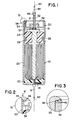
- Figure 1 is a side cross-section of a hermetically sealed aluminum electrolytic capacitor of this invention.
- Figure 2 is a side sectional view of a detail portion 51 illustrating the relative positioning of the tantalum seal ring and the lip of the aluminum can just prior to the welding step in the manufacture of the capacitor of Figure 1.
- Figure 3 shows, in magnified side sectional view, a portion of the detail 51 that includes a section of the weld between tantalum ring of the end seal and the aluminum can.
- Section 10 is comprised of a pair of anodized sheets of aluminum with layers of a porous paper interleaved between them.
- the stack of aluminum sheets and paper is wound about an aluminum mandrel 12 that extends outwardly beyond one end of the section 10. At winding, one of the aluminum sheets that will serve as the anode is attached to the aluminum mandrel 12.
- the section 10 is impregnated with a standard electrolyte based upon dimethylformamide.
- the other and distal end of the aluminum tab 14 is welded to the inside bottom surface of the cylindrical aluminum can 20.
- a solderable tinned-copper cathode lead wire 16 has one end welded to the outside bottom of can 20. There is thus provided internal to the can an all-aluminum electrical access to the aluminum cathode sheet of the wound capacitor section 10 to the can 20.
- the capacitor section 10 is contained within the deep drawn aluminum can 20.
- the bottom of the section 10 is held and prevented from moving relative to can 20 by a close fitting fluoro-plastic seating element 22.
- the top end of the section 10 is held fixed relative to the can 20 by a fluoro-plastic member 24 that snugly surrounds an upper portion of the aluminum mandrel 12.
- the annular plastic member 24 is encircled by a rubber O-ring 26.
- the cathode tab 14 is threaded through a hole in the center of the plastic member 22, and the distal end of cathode tab 14 is welded to the bottom of can 20.
- This tab 14 must be much longer than indicated in Figure 1, and contain more folds, in order that its attachment to the can 20 may be made prior to inserting section 10 in the can 20.
- the capacitor section 10 is pushed into the can 20 thereby folding the long tab 14 and seating the capacitor section 10 against the plastic seating member 22 and the bottom of the can 20.
- An anodized tantalum anode riser wire 31 has one end percussion-weld bonded to the aluminum mandrel 12. The distal end of riser wire 31 extends axially away from the capacitor section 10. The can 20 is then spun so as to form an inwardly directed annular bead 28 that deforms and seals the annular plastic member 24 and rubber O-ring 28 against the can 20.
- This inner seal system all but prevents any electrolyte of section 10 from creeping or diffusing past the walls of the container 20 and along the inner surface of the glass-to-metal end-seal 30.
- a glass-to-metal end seal 30 is comprised of coaxially arranged parts; namely, a tantalum tube 32, an annular glass member 36 surrounding and bonded to the tube 32, and an outer tantalum ring 34 bonded to the glass member 36.
- Assembly of the glass-to-metal seal 30 to the can 20 follows. A small ring 37 of butyl rubber or the like is placed around the riser wire 31. The seal 30 is advanced toward the open mouth of the can 20 so as to thread and push the anode riser wire 31 into the tube 32. The glass-to-metal seal 30 is then pushed into the mouth of the can 20 so as to compress the elastomeric ring 37 against the mandrel 12. This whole assembly is essentially symmetrical about the capacitor axis 42.
- a pulsed laser that is oriented in an axial direction 41 with respect to the axis 42 of the can 20 directs the laser beam at the interface between the aluminum can lip 39 and the tantalum ring 34.
- the beam is caused to travel along this interface while the laser is repetitively pulsed to form a continuous weld 40 along the aluminum-tantalum interface, as shown enlarged in Figure 3.
- This weld 40 may be accomplished by holding the laser beam fixed and rotating the can, or visa versa. It is preferred to maintain an inert atmosphere about the seal during welding to avoid oxidation of the aluminum and tantalum in the region of the weld, e.g. by flooding with argon or another inert gas.
- the laser that was used is a pulsed infra-red glass laser Model No. 14 supplied by Coherent General, Sturbridge, Massachusetts.
- the tantalum seal ring 34 has an outer circumference of 27 mm.
- the can and seal assembly is rotated during welding, at 1/24 revolution per second. Pulsing at a rate of one pulse per second, the welder generates a 26 pulse burst for forming the annular weld in one capacitor package.
- the 26 pulses allows for a two-weld-pulses overlap beyond 360 degrees rotation of the can.
- the riser wire 31 is subsequently cut off about flush with the end of the tube 32, and a weld 44 joins and seals them together.
- An end of a solderable anode lead wire 46 is then connected to the weld 44 to provide electrical access to the capacitor-section anode.
- pulse welding is preferred for its ease of adjustment in heat delivery rate and capability for starting and stopping on command.
Landscapes
- Engineering & Computer Science (AREA)
- Power Engineering (AREA)
- Microelectronics & Electronic Packaging (AREA)
- Fixed Capacitors And Capacitor Manufacturing Machines (AREA)
- Laser Beam Processing (AREA)
- Joining Of Glass To Other Materials (AREA)
Applications Claiming Priority (2)
| Application Number | Priority Date | Filing Date | Title |
|---|---|---|---|
| US07/498,781 US4987519A (en) | 1990-03-26 | 1990-03-26 | Hermetically sealed aluminum electrolytic capacitor |
| US498781 | 1990-03-26 |
Publications (3)
| Publication Number | Publication Date |
|---|---|
| EP0448873A2 true EP0448873A2 (fr) | 1991-10-02 |
| EP0448873A3 EP0448873A3 (en) | 1992-01-29 |
| EP0448873B1 EP0448873B1 (fr) | 1994-03-09 |
Family
ID=23982466
Family Applications (1)
| Application Number | Title | Priority Date | Filing Date |
|---|---|---|---|
| EP90313523A Expired - Lifetime EP0448873B1 (fr) | 1990-03-26 | 1990-12-12 | Condensateur électrolytique à l'aluminium hermétiquement scellé |
Country Status (5)
| Country | Link |
|---|---|
| US (1) | US4987519A (fr) |
| EP (1) | EP0448873B1 (fr) |
| JP (1) | JPH04223320A (fr) |
| CA (1) | CA2029261C (fr) |
| DE (1) | DE69007279T2 (fr) |
Cited By (1)
| Publication number | Priority date | Publication date | Assignee | Title |
|---|---|---|---|---|
| DE10342107B3 (de) * | 2003-09-11 | 2005-02-17 | Epcos Ag | Kondensatormodul |
Families Citing this family (52)
| Publication number | Priority date | Publication date | Assignee | Title |
|---|---|---|---|---|
| US6009348A (en) * | 1998-04-03 | 1999-12-28 | Medtronic, Inc. | Implantable medical device having flat electrolytic capacitor with registered electrode layers |
| US6477037B1 (en) | 1998-04-03 | 2002-11-05 | Medtronic, Inc. | Implantable medical device having flat electrolytic capacitor with miniaturized epoxy connector droplet |
| US6032075A (en) * | 1998-04-03 | 2000-02-29 | Medtronic, Inc. | Implantable medical device with flat aluminum electolytic capacitor |
| US6118652A (en) * | 1998-04-03 | 2000-09-12 | Medtronic, Inc. | Implantable medical device having flat electrolytic capacitor with laser welded cover |
| US6042624A (en) * | 1998-04-03 | 2000-03-28 | Medtronic, Inc. | Method of making an implantable medical device having a flat electrolytic capacitor |
| US6493212B1 (en) | 1998-04-03 | 2002-12-10 | Medtronic, Inc. | Implantable medical device having flat electrolytic capacitor with porous gas vent within electrolyte fill tube |
| US6212063B1 (en) | 1998-04-03 | 2001-04-03 | Medtronic, Inc. | Implantable medical device having flat electrolytic capacitor with connector block and sealed feedthroughs |
| US6445948B1 (en) | 1998-04-03 | 2002-09-03 | Medtronic, Inc. | Implantable medical device having a substantially flat battery |
| US6006133A (en) * | 1998-04-03 | 1999-12-21 | Medtronic, Inc. | Implantable medical device having flat electrolytic capacitor with consolidated electrode assembly |
| US6099600A (en) | 1998-04-03 | 2000-08-08 | Medtronic, Inc. | Method of making a vacuum-treated liquid electrolyte-filled flat electrolytic capacitor |
| US6402793B1 (en) | 1998-04-03 | 2002-06-11 | Medtronic, Inc. | Implantable medical device having flat electrolytic capacitor with cathode/case electrical connections |
| US6141205A (en) | 1998-04-03 | 2000-10-31 | Medtronic, Inc. | Implantable medical device having flat electrolytic capacitor with consolidated electrode tabs and corresponding feedthroughs |
| US6388866B1 (en) | 1998-04-03 | 2002-05-14 | Medtronic, Inc. | Implantable medical device having flat electrolytic capacitor with tailored anode layers |
| US6249423B1 (en) * | 1998-04-21 | 2001-06-19 | Cardiac Pacemakers, Inc. | Electrolytic capacitor and multi-anodic attachment |
| US6187028B1 (en) | 1998-04-23 | 2001-02-13 | Intermedics Inc. | Capacitors having metallized film with tapered thickness |
| US6459566B1 (en) | 1998-06-24 | 2002-10-01 | Medtronic, Inc. | Implantable medical device having flat electrolytic capacitor with laser welded cover |
| US6275729B1 (en) * | 1998-10-02 | 2001-08-14 | Cardiac Pacemakers, Inc. | Smaller electrolytic capacitors for implantable defibrillators |
| US6556863B1 (en) | 1998-10-02 | 2003-04-29 | Cardiac Pacemakers, Inc. | High-energy capacitors for implantable defibrillators |
| US6415647B1 (en) * | 1998-10-30 | 2002-07-09 | Denso Corporation | Compact structure of gas sensor and production method thereof |
| US6307734B1 (en) | 1998-12-31 | 2001-10-23 | General Electric Company | Electrolytic capacitor |
| US6678559B1 (en) | 1999-03-23 | 2004-01-13 | Medtronic, Inc. | Implantable medical device having a capacitor assembly with liner |
| DE19929598C2 (de) * | 1999-06-28 | 2001-04-26 | Epcos Ag | Elektrolyt-Kondensator mit hoher Schwingbelastbarkeit |
| US6385490B1 (en) | 1999-12-16 | 2002-05-07 | Cardiac Pacemakers, Inc. | Capacitors with recessed rivets allow smaller implantable defibrillators |
| US6426864B1 (en) | 2000-06-29 | 2002-07-30 | Cardiac Pacemakers, Inc. | High energy capacitors for implantable defibrillators |
| US6409776B1 (en) | 2000-06-30 | 2002-06-25 | Medtronic, Inc. | Implantable medical device having flat electrolytic capacitor formed with nonthrough-etched and through-hole punctured anode sheets |
| US6621686B1 (en) | 2000-06-30 | 2003-09-16 | Medtronic, Inc. | Implantable medical device having flat electrolytic capacitor formed with partially through-etched and through-hole punctured anode sheets |
| JP4604419B2 (ja) * | 2000-09-29 | 2011-01-05 | 株式会社デンソー | ガスセンサの製造方法及び製造装置 |
| US8065006B2 (en) * | 2002-09-30 | 2011-11-22 | Medtronic, Inc. | Electrochemical cell for implantable medical devices |
| US7301753B2 (en) * | 2005-05-09 | 2007-11-27 | Cardiac Pacemakers, Inc. | Method and apparatus for a capacitor with flexible bus |
| US7206186B1 (en) | 2006-05-31 | 2007-04-17 | Cornell Dubilier Marketing, Inc. | Hermetically sealed electrolytic capacitor |
| US7274551B1 (en) | 2006-10-26 | 2007-09-25 | Cornell-Dubilier Marketing, Inc. | Hermetically sealed electrolytic capacitor |
| DE102008037359A1 (de) * | 2008-08-12 | 2010-02-18 | Gsi Helmholtzzentrum Für Schwerionenforschung Gmbh | Werkstückanordnung |
| WO2011075508A2 (fr) * | 2009-12-18 | 2011-06-23 | Cardiac Pacemakers, Inc. | Electrode de condensateur frittee comprenant une connexion repliee |
| US8605411B2 (en) | 2010-09-16 | 2013-12-10 | Avx Corporation | Abrasive blasted conductive polymer cathode for use in a wet electrolytic capacitor |
| US8259435B2 (en) | 2010-11-01 | 2012-09-04 | Avx Corporation | Hermetically sealed wet electrolytic capacitor |
| US8514547B2 (en) | 2010-11-01 | 2013-08-20 | Avx Corporation | Volumetrically efficient wet electrolytic capacitor |
| EP2671236B1 (fr) | 2011-02-04 | 2019-11-06 | Vishay Sprague, Inc. | Condensateur électrolytique hermétique |
| US8300387B1 (en) | 2011-04-07 | 2012-10-30 | Avx Corporation | Hermetically sealed electrolytic capacitor with enhanced mechanical stability |
| WO2013009720A2 (fr) * | 2011-07-08 | 2013-01-17 | Fastcap Systems Corporation | Dispositif de stockage d'énergie haute température |
| US9558894B2 (en) | 2011-07-08 | 2017-01-31 | Fastcap Systems Corporation | Advanced electrolyte systems and their use in energy storage devices |
| US8451586B2 (en) | 2011-09-13 | 2013-05-28 | Avx Corporation | Sealing assembly for a wet electrolytic capacitor |
| US9129747B2 (en) | 2012-03-16 | 2015-09-08 | Avx Corporation | Abrasive blasted cathode of a wet electrolytic capacitor |
| US9142352B2 (en) | 2013-08-30 | 2015-09-22 | Cornell-Dubilier Marketing, Inc. | Capacitor for high g-force applications |
| US10396343B2 (en) | 2015-05-05 | 2019-08-27 | Cps Technology Holdings Llc | Sealing patch for electrolyte fill hole |
| US9947479B2 (en) | 2015-11-16 | 2018-04-17 | Vishay Sprague, Inc. | Volumetric efficiency wet electrolyte capacitor having a fill port and terminations for surface mounting |
| WO2017136640A1 (fr) | 2016-02-03 | 2017-08-10 | Cornell Dubilier Marketing, Inc. | Condensateur électrolytique hermétiquement clos à double boîtier |
| DE102018107292A1 (de) * | 2018-03-27 | 2019-10-02 | Tdk Electronics Ag | Kondensator und Verfahren zur Herstellung eines Kondensators |
| DE102018107289A1 (de) | 2018-03-27 | 2019-10-02 | Tdk Electronics Ag | Kondensator und Verfahren zur Herstellung eines Kondensators |
| US11189431B2 (en) | 2018-07-16 | 2021-11-30 | Vishay Sprague, Inc. | Low profile wet electrolytic tantalum capacitor |
| US11024464B2 (en) | 2018-08-28 | 2021-06-01 | Vishay Israel Ltd. | Hermetically sealed surface mount polymer capacitor |
| US11742149B2 (en) | 2021-11-17 | 2023-08-29 | Vishay Israel Ltd. | Hermetically sealed high energy electrolytic capacitor and capacitor assemblies with improved shock and vibration performance |
| USD1120880S1 (en) | 2024-05-31 | 2026-03-31 | Vishay Israel Ltd. | Base for a capacitor |
Family Cites Families (10)
| Publication number | Priority date | Publication date | Assignee | Title |
|---|---|---|---|---|
| US2907933A (en) * | 1955-02-21 | 1959-10-06 | Sprague Electric Co | Electrolytic capacitor endseal |
| US3321675A (en) * | 1964-04-14 | 1967-05-23 | Sprague Electric Co | Electrolytic capacitor comprising glass-to-metal and resilient pressure seal combination |
| US3600017A (en) * | 1968-02-26 | 1971-08-17 | Isotronics Inc | Hermetic metal-to-glass seals |
| US3568009A (en) * | 1968-07-26 | 1971-03-02 | Fansteel Inc | Hermetically sealed electrolytic device |
| US3522489A (en) * | 1968-12-04 | 1970-08-04 | Mallory & Co Inc P R | Glass to aluminum seal and hermetically sealed aluminum electrolytic capacitor |
| US3624458A (en) * | 1969-11-26 | 1971-11-30 | Mallory & Co Inc P R | Capacitor having a glass-to-metal seal and an elastomeric seal |
| US3628104A (en) * | 1969-12-08 | 1971-12-14 | Sprague Electric Co | Hermetically sealed aluminum electrolytic capacitor |
| GB1600029A (en) * | 1977-11-24 | 1981-10-14 | Plessey Co Ltd | Electrolytic capacitors |
| US4683516A (en) * | 1986-08-08 | 1987-07-28 | Kennecott Corporation | Extended life capacitor and method |
| US4707424A (en) * | 1986-09-19 | 1987-11-17 | Emerson Electric Co. | Terminal pin and end closure structure for chamber defining housing of hermetic terminal assembly and method of manufacture |
-
1990
- 1990-03-26 US US07/498,781 patent/US4987519A/en not_active Expired - Lifetime
- 1990-11-02 CA CA002029261A patent/CA2029261C/fr not_active Expired - Fee Related
- 1990-12-12 DE DE69007279T patent/DE69007279T2/de not_active Expired - Fee Related
- 1990-12-12 EP EP90313523A patent/EP0448873B1/fr not_active Expired - Lifetime
-
1991
- 1991-03-25 JP JP3060052A patent/JPH04223320A/ja active Pending
Cited By (1)
| Publication number | Priority date | Publication date | Assignee | Title |
|---|---|---|---|---|
| DE10342107B3 (de) * | 2003-09-11 | 2005-02-17 | Epcos Ag | Kondensatormodul |
Also Published As
| Publication number | Publication date |
|---|---|
| CA2029261C (fr) | 1994-08-16 |
| US4987519A (en) | 1991-01-22 |
| DE69007279D1 (de) | 1994-04-14 |
| EP0448873B1 (fr) | 1994-03-09 |
| JPH04223320A (ja) | 1992-08-13 |
| CA2029261A1 (fr) | 1991-09-27 |
| DE69007279T2 (de) | 1994-09-29 |
| EP0448873A3 (en) | 1992-01-29 |
Similar Documents
| Publication | Publication Date | Title |
|---|---|---|
| EP0448873B1 (fr) | Condensateur électrolytique à l'aluminium hermétiquement scellé | |
| US6045944A (en) | Battery and method of manufacturing the same | |
| US6174620B1 (en) | Prismatic sealed battery and method of manufacturing the same | |
| US5484315A (en) | Method for producing a metal-halide discharge lamp with a ceramic discharge vessel | |
| KR101094597B1 (ko) | 전기화학 전지 | |
| EP1763045A1 (fr) | Supports polymériques pour contenir une anode dans un condensateur soumis à de fortes conditions de chocs et vibrations | |
| US20050190530A1 (en) | Molded polymeric cradle for containing an anode in an electrolytic capacitor from high shock and vibration conditions | |
| EP2381234B1 (fr) | Composant fonctionnel comme moyen de mesure de pression doté d'un film métallique en matériau spécial, procédé de soudage d'un film métallique en matériau spécial et dispositif de soudage au rayon laser associé | |
| US5811756A (en) | ARC welding method for aluminum members and welded product excellent in dimensional accuracy and external appearance | |
| JPH1177347A (ja) | アルミニウム薄板のレーザ溶接方法と密閉電池の製造方法及び密閉電池 | |
| US4296458A (en) | Electrolyte capacitors with improved anode-to-lead connection | |
| JPH097560A (ja) | 密閉電池の封口溶接方法 | |
| JP3838764B2 (ja) | 角型密閉電池及びその製造方法 | |
| US3534230A (en) | Electrolytic capacitor having two seals with one having reaction inhibiting surface | |
| JPH08212987A (ja) | 二次電池容器およびその製法 | |
| US4288843A (en) | Capacitor construction with self-locking closure | |
| US7575829B1 (en) | Battery having reduced weight | |
| JP2000331717A (ja) | 密閉二次電池の製造方法および密閉二次電池 | |
| FR2575320A1 (fr) | Emballage protecteur de longue duree contre la corrosion pour des colis fermes hermetiquement dont le contenu est hautement radioactif | |
| JPH1147920A (ja) | アルミニウム製電池ケースの接合方法 | |
| JP2002042742A (ja) | 密閉型電池の製造方法 | |
| US4864582A (en) | Gas laser tube and method for manufacturing the same | |
| US20190272959A1 (en) | Titanium clad nickel termination-pad welded to a titanium tab for a capacitor | |
| US3568009A (en) | Hermetically sealed electrolytic device | |
| JP7446398B2 (ja) | 固体電解コンデンサおよびその製造方法 |
Legal Events
| Date | Code | Title | Description |
|---|---|---|---|
| PUAI | Public reference made under article 153(3) epc to a published international application that has entered the european phase |
Free format text: ORIGINAL CODE: 0009012 |
|
| AK | Designated contracting states |
Kind code of ref document: A2 Designated state(s): DE FR GB IT NL |
|
| PUAL | Search report despatched |
Free format text: ORIGINAL CODE: 0009013 |
|
| AK | Designated contracting states |
Kind code of ref document: A3 Designated state(s): DE FR GB IT NL |
|
| 17P | Request for examination filed |
Effective date: 19920226 |
|
| 17Q | First examination report despatched |
Effective date: 19930223 |
|
| GRAA | (expected) grant |
Free format text: ORIGINAL CODE: 0009210 |
|
| AK | Designated contracting states |
Kind code of ref document: B1 Designated state(s): DE FR GB IT NL |
|
| PG25 | Lapsed in a contracting state [announced via postgrant information from national office to epo] |
Ref country code: IT Free format text: LAPSE BECAUSE OF FAILURE TO SUBMIT A TRANSLATION OF THE DESCRIPTION OR TO PAY THE FEE WITHIN THE PRESCRIBED TIME-LIMIT;WARNING: LAPSES OF ITALIAN PATENTS WITH EFFECTIVE DATE BEFORE 2007 MAY HAVE OCCURRED AT ANY TIME BEFORE 2007. THE CORRECT EFFECTIVE DATE MAY BE DIFFERENT FROM THE ONE RECORDED. Effective date: 19940309 Ref country code: NL Effective date: 19940309 |
|
| REF | Corresponds to: |
Ref document number: 69007279 Country of ref document: DE Date of ref document: 19940414 |
|
| ET | Fr: translation filed | ||
| NLV1 | Nl: lapsed or annulled due to failure to fulfill the requirements of art. 29p and 29m of the patents act | ||
| PLBE | No opposition filed within time limit |
Free format text: ORIGINAL CODE: 0009261 |
|
| STAA | Information on the status of an ep patent application or granted ep patent |
Free format text: STATUS: NO OPPOSITION FILED WITHIN TIME LIMIT |
|
| 26N | No opposition filed | ||
| REG | Reference to a national code |
Ref country code: GB Ref legal event code: IF02 |
|
| PGFP | Annual fee paid to national office [announced via postgrant information from national office to epo] |
Ref country code: GB Payment date: 20031210 Year of fee payment: 14 Ref country code: FR Payment date: 20031210 Year of fee payment: 14 |
|
| PGFP | Annual fee paid to national office [announced via postgrant information from national office to epo] |
Ref country code: DE Payment date: 20031229 Year of fee payment: 14 |
|
| PG25 | Lapsed in a contracting state [announced via postgrant information from national office to epo] |
Ref country code: GB Free format text: LAPSE BECAUSE OF NON-PAYMENT OF DUE FEES Effective date: 20041212 |
|
| PG25 | Lapsed in a contracting state [announced via postgrant information from national office to epo] |
Ref country code: DE Free format text: LAPSE BECAUSE OF NON-PAYMENT OF DUE FEES Effective date: 20050701 |
|
| GBPC | Gb: european patent ceased through non-payment of renewal fee |
Effective date: 20041212 |
|
| PG25 | Lapsed in a contracting state [announced via postgrant information from national office to epo] |
Ref country code: FR Free format text: LAPSE BECAUSE OF NON-PAYMENT OF DUE FEES Effective date: 20050831 |
|
| REG | Reference to a national code |
Ref country code: FR Ref legal event code: ST |