EP0448915B2 - Procédé de construction d'une sous-toiture, sous-toiture construite selon ce procédé et utilisation d'une vis pour l'exécution du procédé - Google Patents
Procédé de construction d'une sous-toiture, sous-toiture construite selon ce procédé et utilisation d'une vis pour l'exécution du procédé Download PDFInfo
- Publication number
- EP0448915B2 EP0448915B2 EP90811029A EP90811029A EP0448915B2 EP 0448915 B2 EP0448915 B2 EP 0448915B2 EP 90811029 A EP90811029 A EP 90811029A EP 90811029 A EP90811029 A EP 90811029A EP 0448915 B2 EP0448915 B2 EP 0448915B2
- Authority
- EP
- European Patent Office
- Prior art keywords
- screw
- screws
- counter
- screwthreaded portion
- rafters
- Prior art date
- Legal status (The legal status is an assumption and is not a legal conclusion. Google has not performed a legal analysis and makes no representation as to the accuracy of the status listed.)
- Expired - Lifetime
Links
- 238000000034 method Methods 0.000 title claims description 11
- 238000010276 construction Methods 0.000 title description 18
- 238000004519 manufacturing process Methods 0.000 claims description 4
- 230000006835 compression Effects 0.000 claims 1
- 238000007906 compression Methods 0.000 claims 1
- 238000009413 insulation Methods 0.000 description 17
- 239000011295 pitch Substances 0.000 description 14
- 125000006850 spacer group Chemical group 0.000 description 13
- 239000002023 wood Substances 0.000 description 6
- 238000012360 testing method Methods 0.000 description 5
- 238000002474 experimental method Methods 0.000 description 4
- 238000009415 formwork Methods 0.000 description 4
- 238000004873 anchoring Methods 0.000 description 3
- 239000006260 foam Substances 0.000 description 3
- 239000004033 plastic Substances 0.000 description 3
- 239000010426 asphalt Substances 0.000 description 2
- 230000004888 barrier function Effects 0.000 description 2
- 238000006073 displacement reaction Methods 0.000 description 2
- 238000005452 bending Methods 0.000 description 1
- 239000003795 chemical substances by application Substances 0.000 description 1
- 238000010586 diagram Methods 0.000 description 1
- 230000000694 effects Effects 0.000 description 1
- 238000004453 electron probe microanalysis Methods 0.000 description 1
- 239000000945 filler Substances 0.000 description 1
- 230000001771 impaired effect Effects 0.000 description 1
- 238000007373 indentation Methods 0.000 description 1
- 238000003780 insertion Methods 0.000 description 1
- 230000037431 insertion Effects 0.000 description 1
- 239000011810 insulating material Substances 0.000 description 1
- 239000000463 material Substances 0.000 description 1
- 239000002184 metal Substances 0.000 description 1
- 239000002557 mineral fiber Substances 0.000 description 1
- 239000011490 mineral wool Substances 0.000 description 1
- KJPHTXTWFHVJIG-UHFFFAOYSA-N n-ethyl-2-[(6-methoxypyridin-3-yl)-(2-methylphenyl)sulfonylamino]-n-(pyridin-3-ylmethyl)acetamide Chemical compound C=1C=C(OC)N=CC=1N(S(=O)(=O)C=1C(=CC=CC=1)C)CC(=O)N(CC)CC1=CC=CN=C1 KJPHTXTWFHVJIG-UHFFFAOYSA-N 0.000 description 1
- 230000035515 penetration Effects 0.000 description 1
- 238000011160 research Methods 0.000 description 1
Images
Classifications
-
- F—MECHANICAL ENGINEERING; LIGHTING; HEATING; WEAPONS; BLASTING
- F16—ENGINEERING ELEMENTS AND UNITS; GENERAL MEASURES FOR PRODUCING AND MAINTAINING EFFECTIVE FUNCTIONING OF MACHINES OR INSTALLATIONS; THERMAL INSULATION IN GENERAL
- F16B—DEVICES FOR FASTENING OR SECURING CONSTRUCTIONAL ELEMENTS OR MACHINE PARTS TOGETHER, e.g. NAILS, BOLTS, CIRCLIPS, CLAMPS, CLIPS OR WEDGES; JOINTS OR JOINTING
- F16B25/00—Screws that cut thread in the body into which they are screwed, e.g. wood screws
- F16B25/001—Screws that cut thread in the body into which they are screwed, e.g. wood screws characterised by the material of the body into which the screw is screwed
- F16B25/0031—Screws that cut thread in the body into which they are screwed, e.g. wood screws characterised by the material of the body into which the screw is screwed the screw being designed to be screwed into different materials, e.g. a layered structure or through metallic and wooden parts
-
- E—FIXED CONSTRUCTIONS
- E04—BUILDING
- E04B—GENERAL BUILDING CONSTRUCTIONS; WALLS, e.g. PARTITIONS; ROOFS; FLOORS; CEILINGS; INSULATION OR OTHER PROTECTION OF BUILDINGS
- E04B7/00—Roofs; Roof construction with regard to insulation
- E04B7/20—Roofs consisting of self-supporting slabs, e.g. able to be loaded
- E04B7/22—Roofs consisting of self-supporting slabs, e.g. able to be loaded the slabs having insulating properties, e.g. laminated with layers of insulating material
-
- E—FIXED CONSTRUCTIONS
- E04—BUILDING
- E04D—ROOF COVERINGS; SKY-LIGHTS; GUTTERS; ROOF-WORKING TOOLS
- E04D12/00—Non-structural supports for roofing materials, e.g. battens, boards
-
- F—MECHANICAL ENGINEERING; LIGHTING; HEATING; WEAPONS; BLASTING
- F16—ENGINEERING ELEMENTS AND UNITS; GENERAL MEASURES FOR PRODUCING AND MAINTAINING EFFECTIVE FUNCTIONING OF MACHINES OR INSTALLATIONS; THERMAL INSULATION IN GENERAL
- F16B—DEVICES FOR FASTENING OR SECURING CONSTRUCTIONAL ELEMENTS OR MACHINE PARTS TOGETHER, e.g. NAILS, BOLTS, CIRCLIPS, CLAMPS, CLIPS OR WEDGES; JOINTS OR JOINTING
- F16B25/00—Screws that cut thread in the body into which they are screwed, e.g. wood screws
- F16B25/0036—Screws that cut thread in the body into which they are screwed, e.g. wood screws characterised by geometric details of the screw
- F16B25/0042—Screws that cut thread in the body into which they are screwed, e.g. wood screws characterised by geometric details of the screw characterised by the geometry of the thread, the thread being a ridge wrapped around the shaft of the screw
- F16B25/0057—Screws that cut thread in the body into which they are screwed, e.g. wood screws characterised by geometric details of the screw characterised by the geometry of the thread, the thread being a ridge wrapped around the shaft of the screw the screw having distinct axial zones, e.g. multiple axial thread sections with different pitch or thread cross-sections
- F16B25/0063—Screws that cut thread in the body into which they are screwed, e.g. wood screws characterised by geometric details of the screw characterised by the geometry of the thread, the thread being a ridge wrapped around the shaft of the screw the screw having distinct axial zones, e.g. multiple axial thread sections with different pitch or thread cross-sections with a non-threaded portion on the shaft of the screw
-
- F—MECHANICAL ENGINEERING; LIGHTING; HEATING; WEAPONS; BLASTING
- F16—ENGINEERING ELEMENTS AND UNITS; GENERAL MEASURES FOR PRODUCING AND MAINTAINING EFFECTIVE FUNCTIONING OF MACHINES OR INSTALLATIONS; THERMAL INSULATION IN GENERAL
- F16B—DEVICES FOR FASTENING OR SECURING CONSTRUCTIONAL ELEMENTS OR MACHINE PARTS TOGETHER, e.g. NAILS, BOLTS, CIRCLIPS, CLAMPS, CLIPS OR WEDGES; JOINTS OR JOINTING
- F16B25/00—Screws that cut thread in the body into which they are screwed, e.g. wood screws
- F16B25/10—Screws performing an additional function to thread-forming, e.g. drill screws or self-piercing screws
- F16B25/103—Screws performing an additional function to thread-forming, e.g. drill screws or self-piercing screws by means of a drilling screw-point, i.e. with a cutting and material removing action
-
- F—MECHANICAL ENGINEERING; LIGHTING; HEATING; WEAPONS; BLASTING
- F16—ENGINEERING ELEMENTS AND UNITS; GENERAL MEASURES FOR PRODUCING AND MAINTAINING EFFECTIVE FUNCTIONING OF MACHINES OR INSTALLATIONS; THERMAL INSULATION IN GENERAL
- F16B—DEVICES FOR FASTENING OR SECURING CONSTRUCTIONAL ELEMENTS OR MACHINE PARTS TOGETHER, e.g. NAILS, BOLTS, CIRCLIPS, CLAMPS, CLIPS OR WEDGES; JOINTS OR JOINTING
- F16B5/00—Joining sheets or plates, e.g. panels, to one another or to strips or bars parallel to them
- F16B5/02—Joining sheets or plates, e.g. panels, to one another or to strips or bars parallel to them by means of fastening members using screw-thread
- F16B5/0275—Joining sheets or plates, e.g. panels, to one another or to strips or bars parallel to them by means of fastening members using screw-thread the screw-threaded element having at least two axially separated threaded portions
Definitions
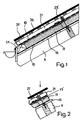
- the invention relates to a method for producing a sub-roof with an insulating layer arranged between rafters and counter battens, the counter battens being connected to the rafters by spacers.
- the roof formwork 13 is located on the rafters 11.
- a vapor barrier and air seal 15 are arranged above the roof formwork 13.
- An insulating layer 17 with a bitumen sheet 19 follows.
- the counter battens 21 are fastened with screws 23 ', which connect the counter battens to the rafters 11 through the layers 19, 17, 15, 13.
- the reference numbers 25 denote the battens on which, for example, a tiled roof 27 is arranged.
- the roof construction described has the disadvantage that the insulation layer 13 is highly compressed in the case of high snow loads. Forces also act to strive to move the roof structure in the direction of the roof pitch. A situation can then arise, as shown in FIG. 2. The counter battens slide down on the screw shaft and the forces acting on the screws cause the screws to deform permanently. The roof structure damaged in this way loses considerable insulation. In bad cases, even the roof can leak.
- FR-A-2 602 810 expressly requires a component with an insulating core made of rigid foam plastic. Two slats are embedded in the foam plastic. For the insulation of the roof, the components are designed so that the slats run horizontally. In addition there is a counter battens, which runs in the direction of the roof slope. The components are attached to the rafters by means of special nails, which are driven approximately vertically into the rafters through the slats and the rigid insulating core. The drawing shows slight deviations from the vertical direction for some nails, as usually occurs when driving in nails.
- FR-A-25 42 787 thus sets itself the task of avoiding the insulation being compressed.
- she proposes a U-shaped spacer, the legs of which are directed downwards and have tips for anchoring in the rafters.
- the part connecting the legs has an opening for fastening the spacer with a nail.
- the side walls penetrate through the insulation layer and the tips at the leg ends dig into the rafters.
- a tip protrudes upward from the part connecting the legs and serves to fasten the counter-batten.
- the disadvantage here is the damage to the insulation caused by the penetration of the legs and the cold bridges created by the legs.
- the spacers are also expensive to manufacture.
- the upstanding tip also creates an accident hazard before attaching the counter-batten.
- the already mentioned DE-A-35 15 419 describes a spacer which consists of a base plate, an upstanding web and a plate for receiving a slat.
- the spacer essentially consists of two L-shaped parts arranged one above the other and connected to one another.
- the base plate has holes for attachment to the rafters. These spacers can only be placed between the insulating plates. This severely limits the scope of the spacers.
- the plate arranged above the base plate for receiving a slat severely impedes the hammering in of nails for fastening. When fastening the slat with nails to the upper plate, there is also the risk of damaging the insulation and bending the web due to hammer blows.
- the spacer also represents a massive cold bridge, whereby the large surface contact of the base plate with the rafters further promotes heat loss.
- a wood screw is known from US-B-2 292 557, which has a thread with a relatively large pitch at the front and a thread with a relatively small pitch at the rear.
- a predetermined breaking point is located shortly after the screw head.
- the screw is used, for example, to eliminate the squeaking of a floor.
- a pilot hole is made which extends through the upper floor into the lower floor.
- the screw causes the upper floor to be pulled down against the lower floor due to the different thread pitches. If these are firmly against each other, the further rotation of the screwdriver causes the screw head to break off at the predetermined breaking point.
- the screw head can then be removed and the hole above the screw filled with a filler.
- a similar screw with threads of different pitches is also described in FR-A-813 643. In both cases, the screw serves to cause two parts to move against each other. There is no suggestion to use the screws to prevent undesired movement of two parts against each other.
- the method of the type mentioned at the outset is modified in such a way that screws are used as supports which also have a threaded section in the rear part of the screw shank in order to act as securing means after driving in the screw, which prevent the counter battens on the screw shank slides down, and that to connect the counter battens to the rafters, the screws are arranged along the respective rafters in a practically vertical plane at a first or a second angle to the rafters. This ensures that the screws transmit the forces generated by high snow loads to the rafters. In this way, the insulation layer is prevented from being compressed by the snow load.
- the counter battens are expediently predrilled before driving in a screw in such a way that a threaded section in the rear part of the screw shaft acts as securing means for anchoring the screw in the counter battens. If this thread has a diameter of 9 mm, for example, the pilot hole can be drilled with a 6 mm diameter drill. A pilot hole is then created, in which the screw is securely anchored in the counter battens with the rear threaded section when the screw is driven in. It is particularly advantageous to use a screw whose thread section in the rear part of the screw shaft has a smaller pitch than the thread section in the front part of the screw shaft.
- the invention also relates to a sub-roof produced by the method according to the invention with an insulating layer arranged between rafters and counter battens, the counter battens being connected to the rafters by means of screws, which also have a threaded section in the rear part of the screw shaft, which acts as securing means which prevent that the counter battens slide down on the screw shaft.
- the invention also relates to the use of a screw for carrying out the method with a threaded section in the rear and in the front part of the screw shaft.
- This screw is characterized in that the front part of the screw is designed as a drill. This enables the screw to be screwed into the rafters with little effort.
- the drill tip can be provided instead of the front threaded section.
- One embodiment of the screw provides that the threaded section in the rear part of the screw shaft has a diameter of approximately 9 mm and the threaded section in the front part of the screw shaft has a diameter of approximately 7 mm. This has the advantage that the screw can easily be pushed through a pre-drilled hole in the counter-batten, the threaded section in the rear part of the screw shaft then being well anchored in the counter-batten when the screw is screwed into the rafters.
- the threaded portion in the rear part of the screw shaft has a smaller pitch, for example 2.5 mm, than the pitch of the threaded section in the front part of the screw shaft, where the pitch is approximately 3.5 mm. This has the advantage that the screw is subjected to tensile stress after being screwed in and that the pressure load of the screw is kept within safe limits in the event of high snow loads.
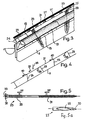
- the roof formwork 13 is located on the rafters 11.
- a vapor barrier and air seal 15 are arranged above the roof formwork 13.
- This is followed by an insulating layer 17 with a bitumen sheet 19.
- the counter battens 21 Above is the counter battens 21.
- Reference numeral 24 denotes a stop bat.
- the reference number 25 refers to the battens on which, for example, a tiled roof 27 is arranged. It is now important that the counter battens 21 are connected to the rafters 11 by means of screws 23 such that securing means 29 located in the area of the counter battens practically prevent a relative movement between the counter battens 21 and screws 23.
- a first embodiment of the screw 23 is shown in Figure 5.
- the screw 23 can be manufactured in different lengths. Lengths of 230, 250, 270 and 300 mm are appropriate.
- the threaded section 29 in the rear part of the screw shaft has a larger diameter, e.g. 9 mm, as the threaded portion 31 in the front part of the screw shaft. The diameter there is about 7 mm. This makes it possible to easily insert the screw 23 into a pilot hole in the counter battens 21, whereupon it can then be screwed into the ratchet 11.
- the screw 23 has a screw head 32 with an internal hexagon 33, a hexagon, a square or another suitable means for this purpose.
- the threads of the threaded portion 31 screw into the rafters 11 and the threads of the threaded portion 29 into the wood of the counter battens 21.
- the threaded section 29 thus acts as a securing means, which prevents a relative movement between the counter battens 21 and the screw 23, as is shown in FIG. 2.
- the pitch S2 of the threaded section 29 is smaller than the pitch of the threaded section 31.
- the pitch S1 is 3.5 mm, while the pitch S2 is only 2.5 mm.
- a second embodiment of the screw 23 according to FIG. 5a differs from that of FIG. 5 in that a drill tip 30 is provided instead of the front threaded section. Otherwise, the screw is basically the same as in FIG. 5.
- the screw of FIG. 5a can be screwed in particularly well.
- the drill tip 30 forms wood chips which are conveyed out of the rafters through the chip channel 28.
- a screw 23 is arranged vertically.
- the other screw 23 is arranged approximately at an angle of ninety degrees to the rafters 11.
- This arrangement is also shown schematically in FIG. 4. It has proven expedient to arrange the screws 23 in a practically vertical plane alternately at a first or a second angle to the rafters, the difference between the two angles being approximately thirty to ninety degrees. If a snow load now generates a force in the direction of arrow 35, a force component arises in the direction of arrow 37, that is, in the direction of the roof slope. This component 37 now strives to move the one screw 23 in the direction of the arrows 39. However, the same force component 37 also strives to move the other screws 23 in the direction of the arrows 40.
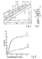
- Tests I and II carried out by the EMPA Federal Materials Testing and Research Institute are described below. These tests were carried out in accordance with the experimental setup shown in FIGS. 6 and 7, in which the stop bar 24 (FIGS. 3 and 1) was omitted.
- the reference numerals are the same as in FIG. 3, so that reference can be made to the above description in this regard.
- the vertical force was transmitted to the roof surface by means of a hydraulic cylinder arranged above the longitudinal center of the rafters 11, a rigid stiff timber (not shown) placed on the counter lath 21 being used to introduce the force.
- the pilot holes on the counter batten 21 had a diameter of 6 mm.
- the roof construction according to the invention has an essential one better mechanical behavior than the well-known roof construction (curve II).
- the displacement of the counter lath 21 is negligible under the loads that occur in practice. It was also found that the counter batten 21 was practically not pressed into the insulating layer even under very high loads.
- the screw 23 has a threaded section 29 which has a larger diameter than the threaded section 31.
- the screws 23 are screwed alternately into the rafters 11 at a first and a second angle. Since the screws 23 with the threaded section 29 are firmly anchored in the counter battens 21, the counter battens 21 cannot slide down the screw shaft and compress the insulation layer 17 even when there is high snow pressure. Thanks to the firm anchoring of the screws 23 in the counter battens 21, there is a rigid bracing between the counter battens 21 and rafters 11, which can also withstand high snow pressure (arrow 35).
Landscapes
- Engineering & Computer Science (AREA)
- General Engineering & Computer Science (AREA)
- Mechanical Engineering (AREA)
- Architecture (AREA)
- Physics & Mathematics (AREA)
- Geometry (AREA)
- Civil Engineering (AREA)
- Structural Engineering (AREA)
- Electromagnetism (AREA)
- Roof Covering Using Slabs Or Stiff Sheets (AREA)
- Vehicle Interior And Exterior Ornaments, Soundproofing, And Insulation (AREA)
- Joining Of Building Structures In Genera (AREA)
- Closures For Containers (AREA)
- Gripping Jigs, Holding Jigs, And Positioning Jigs (AREA)
- Clamps And Clips (AREA)
- Bolts, Nuts, And Washers (AREA)
Claims (13)
- Procédé de construction d'une sous-toiture comportant une couche isolante (17) disposée entre les chevrons (11) et le contre-lattis (21), le contre-lattis (21) étant raccordé aux chevrons (11) par des éléments porteurs, caractérisé en ce qu'on utilise, comme éléments porteurs, des vis (23) qui présentent également, dans la partie arrière de la tige de vis, un segment fileté (29) destiné à servir, après que la vis a été enfoncée, de moyen de sécurité qui s'oppose à ce que le contre-lattis (21) glisse vers le bas le long de la tige de vis, et en ce que, pour le raccordement du contre-lattis (21) aux chevrons (il), les vis (23) sont disposées le long de chaque chevron, dans un plan pratiquement vertical, de manière à former respectivement un premier et un second angle avec le chevron.
- Procédé selon la revendication 1, caractérisé en ce que les vis (23) sont disposées les unes verticalement et les autres de manière à former un angle d'environ 90° avec les chevrons (11).
- Procédé selon la revendication 1 ou 2, caractérisé en ce que la différence entre les deux angles est d'environ 30 à 90°.
- Procédé selon l'une quelconque des revendications 1 à 8, caractérisé en ce qu'avant qu'une vis (23) ne soit enfoncée, il est formé, dans le contre-lattis (21), un pré-trou tel que le segment fileté (29) à la partie arrière de la tige de vis serve de moyen de sécurité pour l'ancrage de la vis (23) dans le contre-lattis (21).
- Procédé selon la revendication 4, caractérisé en ce qu'on utilise une vis (23) dont le segment fileté (29) à la partie arrière de la tige de vis présente un pas plus faible que le segment fileté (31) à la partie avant de la tige de vis, de telle manière que la couche isolante (17) soit légèrement comprimée par l'enfoncement de la vis (23) et, de la sorte, exerce un effort de traction sur la vis (23).
- Sous-toiture construite par le procédé selon l'une quelconque des revendications 1 à 5 et comportant une couche isolante (17) disposée entre les chevrons (11) et le contre-lattis (21), le contre-lattis (21) étant raccordé aux chevrons (11) au moyen de vis (23) qui présentent également, dans la partie arrière de la tige de vis, un segment fileté (29) qui sert de moyen de sécurité s'opposant à ce que le contre-lattis (21) glisse vers le bas le long de la tige de vis.
- Sous-toiture selon la revendication 6, caractérisée en ce que les vis (32) sont disposées le long des chevrons (11), dans un plan pratiquement vertical, de manière à former alternativement un premier et un second angle avec le chevron (11).
- Sous-toiture selon la revendication 7, caractérisée en ce que les vis (23) sont disposées les unes verticalement et les autres de manière à former un angle d'environ 90° avec le chevron (11).
- Sous-toiture selon la revendication 8, caractérisée en ce que la différence entre les deux angles est d'environ 30 à 90°.
- Sous-toiture selon l'une quelconque des revendications à à 9, caractérisée en ce que le segment fileté (29) à la partie arrière de la tige de vis présente un pas plus faible que le segment fileté (31) à la partie avant de la tige de vis et produit ainsi une légère compression de la couche isolante (17), ce qui fait que la vis (23) est sollicitée à la traction.
- Utilisation d'une vis comportant des segments filetés (29, 31) à la partie arrière et à la partie avant de la tige de vis, le segment fileté (29) à la partie arrière de la tige de vis présentant un plus grand diamètre que le diamètre du segment fileté à la partie avant de la tige de vis et la partie avant de la vis étant réalisée sous forme de foret (30), pour la construction d'une sous-toiture selon l'une quelconque des revendication 6 à 10.
- Utilisation d'une vis selon la revendication 11, caractérisée en ce que le segment fileté (29) à la partie arrière de la tige de vis présente un diamètre de 9 mm et le segment fileté (31) à la partie avant de la tige des vis présente un diamètre de 7mm.
- Utilisation d'une vis selon la revendication 11 ou 12, caractérisée en ce que le segment fileté (29) à la partie arrière de la tige de vis présente un plus faible pas, par exemple de 2,5 mm, que le pas du segment fileté (31) à la partie avant, où le pas est par exemple de 3,5 mm.
Applications Claiming Priority (2)
| Application Number | Priority Date | Filing Date | Title |
|---|---|---|---|
| CH1028/90 | 1990-03-28 | ||
| CH1028/90A CH682830A5 (de) | 1990-03-28 | 1990-03-28 | Verfahren zur Herstellung eines Unterdachs, Unterdach, hergestellt nach dem Verfahren und Schraube zur Durchführung des Verfahrens. |
Publications (3)
| Publication Number | Publication Date |
|---|---|
| EP0448915A1 EP0448915A1 (fr) | 1991-10-02 |
| EP0448915B1 EP0448915B1 (fr) | 1993-06-09 |
| EP0448915B2 true EP0448915B2 (fr) | 1997-10-15 |
Family
ID=4200766
Family Applications (1)
| Application Number | Title | Priority Date | Filing Date |
|---|---|---|---|
| EP90811029A Expired - Lifetime EP0448915B2 (fr) | 1990-03-28 | 1990-12-27 | Procédé de construction d'une sous-toiture, sous-toiture construite selon ce procédé et utilisation d'une vis pour l'exécution du procédé |
Country Status (5)
| Country | Link |
|---|---|
| EP (1) | EP0448915B2 (fr) |
| AT (1) | ATE90411T1 (fr) |
| CH (1) | CH682830A5 (fr) |
| DE (1) | DE59001712D1 (fr) |
| DK (1) | DK0448915T3 (fr) |
Cited By (1)
| Publication number | Priority date | Publication date | Assignee | Title |
|---|---|---|---|---|
| DE102006039749A1 (de) * | 2006-08-24 | 2008-03-27 | Ludwig Hettich & Co. | Geneigte Unterdachkonstruktion und Verfahren zum Herstellen eines geneigten Unterdaches |
Families Citing this family (12)
| Publication number | Priority date | Publication date | Assignee | Title |
|---|---|---|---|---|
| DE19610267A1 (de) * | 1996-03-15 | 1997-09-18 | Pfleiderer Daemmstofftechnik G | Dachkonstruktion |
| DE29607265U1 (de) * | 1996-04-22 | 1997-06-26 | Sfs Handels Holding Ag, Heerbrugg | Schraube zum Einsatz bei einem Unterdach |
| ATE241059T1 (de) * | 1997-06-09 | 2003-06-15 | Sfs Intec Holding Ag | Koppelpfette aus zwei oder mehreren, in längsrichtung einander überlappend aneinander anschliessenden holzbalken sowie befestigungselement zum verbinden von jeweils zwei einander überlappenden endbereichen von holzbalken zum einsatz bei einer koppelpfette |
| AU9745398A (en) | 1997-09-22 | 1999-04-12 | Sfs Industrie Holding Ag | Screw for fixing wooden laths on a roof substructure or a wall foundation |
| DE29805784U1 (de) * | 1998-03-30 | 1999-08-05 | Sfs Industrie Holding Ag, Heerbrugg | Schraube zur Befestigung von Latten aus Holz auf einem Dach- oder Wandunterbau |
| DE202005007886U1 (de) | 2005-05-19 | 2006-05-18 | Sfs Intec Holding Ag | Wandaufbau bei einem Gebäude |
| DE102009005916A1 (de) * | 2009-01-09 | 2010-07-22 | Adolf Würth GmbH & Co. KG | Schraube |
| DE102009038205B3 (de) * | 2009-08-20 | 2011-02-24 | Eternit Ag | Wellplatten-Dacheindeckung |
| DE102009049091A1 (de) * | 2009-10-02 | 2011-04-07 | Adolf Würth GmbH & Co. KG | Befestigungselement |
| US11236507B2 (en) | 2015-08-26 | 2022-02-01 | Omg, Inc. | Structural truss module with fastener web and manufacturing method therefor |
| US11519174B2 (en) | 2015-08-26 | 2022-12-06 | Omg, Inc. | Building structure formed by truss modules and method of forming |
| CN111042420A (zh) * | 2019-12-23 | 2020-04-21 | 青岛泰合洋房建设有限公司 | 一种轻钢别墅的屋盖施工工艺 |
Family Cites Families (7)
| Publication number | Priority date | Publication date | Assignee | Title |
|---|---|---|---|---|
| FR813643A (fr) * | 1936-02-12 | 1937-06-05 | Article perfectionné de visserie | |
| US2292557A (en) * | 1941-09-25 | 1942-08-11 | Wilson Wealey | Wood screw |
| DE2944241A1 (de) * | 1978-11-02 | 1980-05-14 | Landolt Fritz Ag | Isolationsunterdach |
| CH647832A5 (fr) * | 1983-03-14 | 1985-02-15 | Praz Jean Luc | Dispositif pour la fixation d'une isolation de toiture. |
| FR2571764B1 (fr) * | 1984-10-11 | 1987-08-14 | Isobox | Perfectionnements apportes aux systemes isolants supports de couvertures |
| DE3515419C1 (de) * | 1985-04-29 | 1986-08-14 | Walter Dipl.-Ing. 4630 Bochum Holzapfel | Abstandhalter zur Distanzierung einer unter einer Dachabdeckung vorhandenen Dachunterkonstruktion von der tragenden Dachkonstruktion |
| FR2602810B1 (fr) * | 1986-07-28 | 1991-04-26 | Rhenane Sa | Caisson isolant chevronne support de couverture |
-
1990
- 1990-03-28 CH CH1028/90A patent/CH682830A5/de not_active IP Right Cessation
- 1990-12-27 DK DK90811029.9T patent/DK0448915T3/da not_active Application Discontinuation
- 1990-12-27 EP EP90811029A patent/EP0448915B2/fr not_active Expired - Lifetime
- 1990-12-27 AT AT90811029T patent/ATE90411T1/de not_active IP Right Cessation
- 1990-12-27 DE DE9090811029T patent/DE59001712D1/de not_active Expired - Lifetime
Cited By (1)
| Publication number | Priority date | Publication date | Assignee | Title |
|---|---|---|---|---|
| DE102006039749A1 (de) * | 2006-08-24 | 2008-03-27 | Ludwig Hettich & Co. | Geneigte Unterdachkonstruktion und Verfahren zum Herstellen eines geneigten Unterdaches |
Also Published As
| Publication number | Publication date |
|---|---|
| DK0448915T3 (da) | 1993-10-11 |
| DE59001712D1 (de) | 1993-07-15 |
| CH682830A5 (de) | 1993-11-30 |
| EP0448915B1 (fr) | 1993-06-09 |
| EP0448915A1 (fr) | 1991-10-02 |
| ATE90411T1 (de) | 1993-06-15 |
Similar Documents
| Publication | Publication Date | Title |
|---|---|---|
| EP1007809B1 (fr) | Dispositif de renfort pour structures porteuses | |
| EP0448915B2 (fr) | Procédé de construction d'une sous-toiture, sous-toiture construite selon ce procédé et utilisation d'une vis pour l'exécution du procédé | |
| EP1883737B1 (fr) | Structure de mur pour batiment | |
| EP1015774B1 (fr) | Fixation des lattes de bois sur le platelage d'un toit ou la fondation d'un mur composé entre autres de bois | |
| EP2715156B1 (fr) | Système de fixation d'une façade isolante et dispositif de fixation prévu à cet effet | |
| DE3607607A1 (de) | Befestigung von dichtungsbahnen und/oder daemmplatten am flachdach und dafuer bestimmte befestigungseinrichtung | |
| CH678959A5 (fr) | ||
| EP1899613A1 (fr) | Vis d'ancrage | |
| DE8632187U1 (de) | Vorrichtung zum Befestigen von Fasaden-Bauelementen (Fassadenelementen) an Konstruktionselementen | |
| EP0988430B1 (fr) | Panne de couplage constituee de deux ou plusieurs poutres en bois jointes l'une a l'autre par chevauchement longitudinal, ainsi qu'element de fixation pour relier deux zones d'extremite se chevauchant de poutres en bois a utiliser pour une panne de couplage | |
| DE2061901A1 (de) | Einspannvorrichtung für Kunststoff-Rahmen für Fenster und Türen, insbesondere aus Hart-PVC | |
| EP1078135A1 (fr) | Systeme de fasade pour le parement d'un edifice | |
| DE102023111184A1 (de) | Verstärkung für einen Porenbetonträger, Porenbetonträger, Verwendung eines Porenbetonträgers, Verfahren zum Verstärken eines Porenbetonträgers und Verwendung einer Verstärkung | |
| EP0289038B1 (fr) | Liaison pour piéces de construction en beton cellulaire | |
| DE4322741C2 (de) | Maueranschlußanker | |
| EP1160386A1 (fr) | Elément isolant, façade ventilée et procédé pour sa réalisation | |
| EP0052158A1 (fr) | Bloc-support pour revêtements de façades | |
| DE3444801A1 (de) | Aus einem ankersteg und einem ankerdorn bestehender anker zum anbringen von wandbekleidungsplatten an bauwerkswaenden | |
| EP1936054B9 (fr) | Languette de traction destinée à la fixation de plaques murales en béton poreux, ainsi que système de plaques murales en béton poreux doté de languettes de traction | |
| DE29915079U1 (de) | Verbindungsmittel, insbesondere Einpreßdübel, für Sparren und Bohlen aus Holz | |
| DE20120208U1 (de) | Verbindung von aus Holzbalken oder -Latten bestehenden Pfosten und Riegeln zur Bildung von Wandelementen | |
| WO2026032956A1 (fr) | Ensemble comprenant un revêtement de terrasse | |
| DE4101133C2 (de) | Verfahren zur Befestigung von Bahnen an Holzwolle-Leichtbauplatten | |
| EP1288388A1 (fr) | Profile intercalaire et construction associee de toit ou paroi | |
| DE19843128C1 (de) | Befestigungsmittel zur Befestigung eines Windrispenbandes an einem Dachsparren |
Legal Events
| Date | Code | Title | Description |
|---|---|---|---|
| PUAI | Public reference made under article 153(3) epc to a published international application that has entered the european phase |
Free format text: ORIGINAL CODE: 0009012 |
|
| 17P | Request for examination filed |
Effective date: 19901231 |
|
| AK | Designated contracting states |
Kind code of ref document: A1 Designated state(s): AT BE CH DE DK FR GB IT LI LU NL SE |
|
| 17Q | First examination report despatched |
Effective date: 19920213 |
|
| GRAA | (expected) grant |
Free format text: ORIGINAL CODE: 0009210 |
|
| AK | Designated contracting states |
Kind code of ref document: B1 Designated state(s): AT BE CH DE DK FR GB IT LI LU NL SE |
|
| REF | Corresponds to: |
Ref document number: 90411 Country of ref document: AT Date of ref document: 19930615 Kind code of ref document: T |
|
| REF | Corresponds to: |
Ref document number: 59001712 Country of ref document: DE Date of ref document: 19930715 |
|
| ET | Fr: translation filed | ||
| ITF | It: translation for a ep patent filed | ||
| GBT | Gb: translation of ep patent filed (gb section 77(6)(a)/1977) |
Effective date: 19930722 |
|
| REG | Reference to a national code |
Ref country code: DK Ref legal event code: T3 |
|
| EPTA | Lu: last paid annual fee | ||
| PLBI | Opposition filed |
Free format text: ORIGINAL CODE: 0009260 |
|
| 26 | Opposition filed |
Opponent name: GLAROMAT AG Effective date: 19940307 Opponent name: TOPROC AG Effective date: 19940307 |
|
| NLR1 | Nl: opposition has been filed with the epo |
Opponent name: GLAROMAT AG Opponent name: TROPOC AG |
|
| EAL | Se: european patent in force in sweden |
Ref document number: 90811029.9 |
|
| REG | Reference to a national code |
Ref country code: CH Ref legal event code: PUE Owner name: AUGUST KUNZ TRANSFER- SFS HANDELS HOLDING AG |
|
| RAP2 | Party data changed (patent owner data changed or rights of a patent transferred) |
Owner name: SFS HANDELS HOLDING AG |
|
| RIN2 | Information on inventor provided after grant (corrected) | ||
| RIN2 | Information on inventor provided after grant (corrected) |
Free format text: KUNZ, AUGUST |
|
| REG | Reference to a national code |
Ref country code: GB Ref legal event code: 732E |
|
| REG | Reference to a national code |
Ref country code: FR Ref legal event code: TP |
|
| NLS | Nl: assignments of ep-patents |
Owner name: SFS HANDELS HOLDING AG |
|
| NLT2 | Nl: modifications (of names), taken from the european patent patent bulletin |
Owner name: SFS HANDELS HOLDING AG |
|
| PLAW | Interlocutory decision in opposition |
Free format text: ORIGINAL CODE: EPIDOS IDOP |
|
| PLAW | Interlocutory decision in opposition |
Free format text: ORIGINAL CODE: EPIDOS IDOP |
|
| PUAH | Patent maintained in amended form |
Free format text: ORIGINAL CODE: 0009272 |
|
| STAA | Information on the status of an ep patent application or granted ep patent |
Free format text: STATUS: PATENT MAINTAINED AS AMENDED |
|
| 27A | Patent maintained in amended form |
Effective date: 19971015 |
|
| AK | Designated contracting states |
Kind code of ref document: B2 Designated state(s): AT BE CH DE DK FR GB IT LI LU NL SE |
|
| REG | Reference to a national code |
Ref country code: CH Ref legal event code: AEN Free format text: AUFRECHTERHALTUNG DES PATENTES IN GEAENDERTER FORM |
|
| NLR2 | Nl: decision of opposition | ||
| ITF | It: translation for a ep patent filed | ||
| ET3 | Fr: translation filed ** decision concerning opposition | ||
| GBTA | Gb: translation of amended ep patent filed (gb section 77(6)(b)/1977) | ||
| NLR3 | Nl: receipt of modified translations in the netherlands language after an opposition procedure | ||
| REG | Reference to a national code |
Ref country code: DK Ref legal event code: T4 |
|
| REG | Reference to a national code |
Ref country code: GB Ref legal event code: IF02 |
|
| PGFP | Annual fee paid to national office [announced via postgrant information from national office to epo] |
Ref country code: LU Payment date: 20020830 Year of fee payment: 13 |
|
| PGFP | Annual fee paid to national office [announced via postgrant information from national office to epo] |
Ref country code: BE Payment date: 20021004 Year of fee payment: 13 Ref country code: GB Payment date: 20021004 Year of fee payment: 13 |
|
| PGFP | Annual fee paid to national office [announced via postgrant information from national office to epo] |
Ref country code: SE Payment date: 20021108 Year of fee payment: 13 |
|
| PGFP | Annual fee paid to national office [announced via postgrant information from national office to epo] |
Ref country code: DK Payment date: 20021203 Year of fee payment: 13 |
|
| PGFP | Annual fee paid to national office [announced via postgrant information from national office to epo] |
Ref country code: NL Payment date: 20021230 Year of fee payment: 13 |
|
| PG25 | Lapsed in a contracting state [announced via postgrant information from national office to epo] |
Ref country code: LU Free format text: LAPSE BECAUSE OF NON-PAYMENT OF DUE FEES Effective date: 20031227 Ref country code: GB Free format text: LAPSE BECAUSE OF NON-PAYMENT OF DUE FEES Effective date: 20031227 |
|
| PG25 | Lapsed in a contracting state [announced via postgrant information from national office to epo] |
Ref country code: SE Free format text: LAPSE BECAUSE OF NON-PAYMENT OF DUE FEES Effective date: 20031228 |
|
| PG25 | Lapsed in a contracting state [announced via postgrant information from national office to epo] |
Ref country code: BE Free format text: LAPSE BECAUSE OF NON-PAYMENT OF DUE FEES Effective date: 20031231 |
|
| PG25 | Lapsed in a contracting state [announced via postgrant information from national office to epo] |
Ref country code: DK Free format text: LAPSE BECAUSE OF NON-PAYMENT OF DUE FEES Effective date: 20040102 |
|
| BERE | Be: lapsed |
Owner name: *SFS HANDELS HOLDING A.G. Effective date: 20031231 |
|
| PG25 | Lapsed in a contracting state [announced via postgrant information from national office to epo] |
Ref country code: NL Free format text: LAPSE BECAUSE OF NON-PAYMENT OF DUE FEES Effective date: 20040701 |
|
| EUG | Se: european patent has lapsed | ||
| REG | Reference to a national code |
Ref country code: DK Ref legal event code: EBP |
|
| GBPC | Gb: european patent ceased through non-payment of renewal fee |
Effective date: 20031227 |
|
| NLV4 | Nl: lapsed or anulled due to non-payment of the annual fee |
Effective date: 20040701 |
|
| REG | Reference to a national code |
Ref country code: CH Ref legal event code: NV Representative=s name: JUERG PLUESS SFS INTEC AG INTELLECTUAL PROPERTY MA |
|
| PGFP | Annual fee paid to national office [announced via postgrant information from national office to epo] |
Ref country code: AT Payment date: 20091214 Year of fee payment: 20 Ref country code: CH Payment date: 20091105 Year of fee payment: 20 |
|
| PGFP | Annual fee paid to national office [announced via postgrant information from national office to epo] |
Ref country code: FR Payment date: 20100106 Year of fee payment: 20 |
|
| PGFP | Annual fee paid to national office [announced via postgrant information from national office to epo] |
Ref country code: DE Payment date: 20091230 Year of fee payment: 20 |
|
| REG | Reference to a national code |
Ref country code: CH Ref legal event code: PL |
|
| PG25 | Lapsed in a contracting state [announced via postgrant information from national office to epo] |
Ref country code: IT Free format text: LAPSE BECAUSE OF NON-PAYMENT OF DUE FEES Effective date: 20091227 |
|
| PGFP | Annual fee paid to national office [announced via postgrant information from national office to epo] |
Ref country code: IT Payment date: 20091211 Year of fee payment: 20 |
|
| PGRI | Patent reinstated in contracting state [announced from national office to epo] |
Ref country code: IT Effective date: 20110616 |
|
| PG25 | Lapsed in a contracting state [announced via postgrant information from national office to epo] |
Ref country code: DE Free format text: LAPSE BECAUSE OF EXPIRATION OF PROTECTION Effective date: 20101227 |