EP0448922B1 - Joint d'étanchéité - Google Patents
Joint d'étanchéité Download PDFInfo
- Publication number
- EP0448922B1 EP0448922B1 EP90890085A EP90890085A EP0448922B1 EP 0448922 B1 EP0448922 B1 EP 0448922B1 EP 90890085 A EP90890085 A EP 90890085A EP 90890085 A EP90890085 A EP 90890085A EP 0448922 B1 EP0448922 B1 EP 0448922B1
- Authority
- EP
- European Patent Office
- Prior art keywords
- sealing ring
- sealing
- sleeve
- ring portion
- thickened
- Prior art date
- Legal status (The legal status is an assumption and is not a legal conclusion. Google has not performed a legal analysis and makes no representation as to the accuracy of the status listed.)
- Expired - Lifetime
Links
- 238000007789 sealing Methods 0.000 title claims description 136
- -1 respectively Polymers 0.000 claims description 7
- 229920001971 elastomer Polymers 0.000 claims description 6
- 239000004033 plastic Substances 0.000 claims description 6
- 229920003023 plastic Polymers 0.000 claims description 6
- 239000004698 Polyethylene Substances 0.000 claims description 4
- 239000000463 material Substances 0.000 claims description 4
- 229910052751 metal Inorganic materials 0.000 claims description 4
- 239000002184 metal Substances 0.000 claims description 4
- 229920000573 polyethylene Polymers 0.000 claims description 4
- 229920001577 copolymer Polymers 0.000 claims description 3
- 239000000806 elastomer Substances 0.000 claims description 3
- 239000005060 rubber Substances 0.000 claims description 3
- 229920001169 thermoplastic Polymers 0.000 claims description 3
- 239000004416 thermosoftening plastic Substances 0.000 claims description 3
- 230000008878 coupling Effects 0.000 claims 3
- 238000010168 coupling process Methods 0.000 claims 3
- 238000005859 coupling reaction Methods 0.000 claims 3
- 230000001154 acute effect Effects 0.000 claims 1
- 238000003483 aging Methods 0.000 claims 1
- 238000004140 cleaning Methods 0.000 description 8
- 230000008719 thickening Effects 0.000 description 6
- 238000004519 manufacturing process Methods 0.000 description 5
- 239000003673 groundwater Substances 0.000 description 4
- 230000000694 effects Effects 0.000 description 3
- 238000003780 insertion Methods 0.000 description 3
- 230000037431 insertion Effects 0.000 description 3
- 239000011435 rock Substances 0.000 description 3
- 230000035515 penetration Effects 0.000 description 2
- 239000004576 sand Substances 0.000 description 2
- XLYOFNOQVPJJNP-UHFFFAOYSA-N water Substances O XLYOFNOQVPJJNP-UHFFFAOYSA-N 0.000 description 2
- 229910000851 Alloy steel Inorganic materials 0.000 description 1
- 229910001018 Cast iron Inorganic materials 0.000 description 1
- RYGMFSIKBFXOCR-UHFFFAOYSA-N Copper Chemical compound [Cu] RYGMFSIKBFXOCR-UHFFFAOYSA-N 0.000 description 1
- VVQNEPGJFQJSBK-UHFFFAOYSA-N Methyl methacrylate Chemical compound COC(=O)C(C)=C VVQNEPGJFQJSBK-UHFFFAOYSA-N 0.000 description 1
- 229920005372 Plexiglas® Polymers 0.000 description 1
- 239000004721 Polyphenylene oxide Substances 0.000 description 1
- 239000004743 Polypropylene Substances 0.000 description 1
- 208000031074 Reinjury Diseases 0.000 description 1
- 229910000831 Steel Inorganic materials 0.000 description 1
- 238000004026 adhesive bonding Methods 0.000 description 1
- 229910052782 aluminium Inorganic materials 0.000 description 1
- XAGFODPZIPBFFR-UHFFFAOYSA-N aluminium Chemical compound [Al] XAGFODPZIPBFFR-UHFFFAOYSA-N 0.000 description 1
- 239000010425 asbestos Substances 0.000 description 1
- 239000004568 cement Substances 0.000 description 1
- 238000011109 contamination Methods 0.000 description 1
- 229910052802 copper Inorganic materials 0.000 description 1
- 239000010949 copper Substances 0.000 description 1
- 230000000875 corresponding effect Effects 0.000 description 1
- 230000006378 damage Effects 0.000 description 1
- 238000006073 displacement reaction Methods 0.000 description 1
- 238000003912 environmental pollution Methods 0.000 description 1
- 230000002349 favourable effect Effects 0.000 description 1
- 210000003608 fece Anatomy 0.000 description 1
- 239000000835 fiber Substances 0.000 description 1
- 239000011151 fibre-reinforced plastic Substances 0.000 description 1
- 239000011152 fibreglass Substances 0.000 description 1
- 239000007789 gas Substances 0.000 description 1
- 238000009434 installation Methods 0.000 description 1
- 239000007788 liquid Substances 0.000 description 1
- 150000002739 metals Chemical class 0.000 description 1
- 229920000515 polycarbonate Polymers 0.000 description 1
- 239000004417 polycarbonate Substances 0.000 description 1
- 229920000193 polymethacrylate Polymers 0.000 description 1
- 229920001955 polyphenylene ether Polymers 0.000 description 1
- 229920006380 polyphenylene oxide Polymers 0.000 description 1
- 229920001155 polypropylene Polymers 0.000 description 1
- 229920000915 polyvinyl chloride Polymers 0.000 description 1
- 239000004800 polyvinyl chloride Substances 0.000 description 1
- 230000001681 protective effect Effects 0.000 description 1
- 229910052895 riebeckite Inorganic materials 0.000 description 1
- 239000003566 sealing material Substances 0.000 description 1
- 239000002689 soil Substances 0.000 description 1
- 239000010959 steel Substances 0.000 description 1
- 229910052572 stoneware Inorganic materials 0.000 description 1
- 238000003860 storage Methods 0.000 description 1
- 239000000126 substance Substances 0.000 description 1
- 239000002351 wastewater Substances 0.000 description 1
Images


Classifications
-
- F—MECHANICAL ENGINEERING; LIGHTING; HEATING; WEAPONS; BLASTING
- F16—ENGINEERING ELEMENTS AND UNITS; GENERAL MEASURES FOR PRODUCING AND MAINTAINING EFFECTIVE FUNCTIONING OF MACHINES OR INSTALLATIONS; THERMAL INSULATION IN GENERAL
- F16L—PIPES; JOINTS OR FITTINGS FOR PIPES; SUPPORTS FOR PIPES, CABLES OR PROTECTIVE TUBING; MEANS FOR THERMAL INSULATION IN GENERAL
- F16L21/00—Joints with sleeve or socket
- F16L21/02—Joints with sleeve or socket with elastic sealing rings between pipe and sleeve or between pipe and socket, e.g. with rolling or other prefabricated profiled rings
- F16L21/03—Joints with sleeve or socket with elastic sealing rings between pipe and sleeve or between pipe and socket, e.g. with rolling or other prefabricated profiled rings placed in the socket before connection
-
- F—MECHANICAL ENGINEERING; LIGHTING; HEATING; WEAPONS; BLASTING
- F16—ENGINEERING ELEMENTS AND UNITS; GENERAL MEASURES FOR PRODUCING AND MAINTAINING EFFECTIVE FUNCTIONING OF MACHINES OR INSTALLATIONS; THERMAL INSULATION IN GENERAL
- F16L—PIPES; JOINTS OR FITTINGS FOR PIPES; SUPPORTS FOR PIPES, CABLES OR PROTECTIVE TUBING; MEANS FOR THERMAL INSULATION IN GENERAL
- F16L17/00—Joints with packing adapted to sealing by fluid pressure
- F16L17/02—Joints with packing adapted to sealing by fluid pressure with sealing rings arranged between outer surface of pipe and inner surface of sleeve or socket
- F16L17/025—Joints with packing adapted to sealing by fluid pressure with sealing rings arranged between outer surface of pipe and inner surface of sleeve or socket the sealing rings having radially directed ribs
Definitions
- the invention relates to sealing arrangements for pipe connections, in particular plug-in connections, preferably for plastic or metal pipes, in which the end of one pipe, which is advantageously designed with the exception of the pointed end with a cylindrical outer jacket, is inserted into the end of the other pipe which is widened to form a connecting sleeve, wherein this widening at a distance from the inside of the sleeve has an annular recess of different depths for receiving the sealing ring, as well as this sleeve is advantageously designed with a cylindrical inner jacket in addition to the recess and the sealing ring has areas of different thicknesses, a thickened ring part of a trapezoidal cross section in particular being provided in the area of the sleeve end and with this thickened sealing ring part, at least one sealing part which is substantially thinner than this is connected, and the sealing flank on the sealing ring when the sealing ring is inserted into the sleeve of the thickened sealing ring part is drawn inward beyond the respective inner wall of the socket
- Sealing systems for pipe connections currently in use are usually with only one, at most with two sealing lips, e.g. according to US-A-3 856 315. Due to the spigot end of the pipe, these sealing lips can be easily damaged when inserted or brought with the smallest rock and the entire pipe system can become leaky, which should be avoided especially in drain and sewer lines due to the discharge of faecal wastewater and the resulting environmental pollution or groundwater contamination. Conversely, in the case of cable duct systems, for reasons of safety and perfect functioning against water entering from outside, e.g. Groundwater, absolute tightness required. This is also not guaranteed by means of the slightly conical inner surface of the sealing ring of the pipe connection according to the aforementioned US Pat. No. 3,856,315.
- sealing rings for pipe connections have already been proposed, which, like the designs according to AT-B-366 210, AT-B-379 446, GB-A-1 353 929 or DE-A-21 30 574, GB -A-1 350 593 and DE-A-20 10 826 have three or more sealing lips.
- adequate precautions against the penetration of foreign bodies are missing, for example Small rock, sand or the like. when inserting the tip end of the pipe into the sleeve or during operation. Damage to the seal or the sealing lips and leakage of the pipe connection can therefore not be avoided.
- the thickened sealing ring part and the part of the annular recess of the sleeve pipe with greater depth having a cross section with a steep angle of 15 ° to 25 °, in particular of 20 °, with transverse axial planes have enclosing flanks, and that when the sealing ring is inserted into the sleeve, the flank of the thickened sealing ring part on the end of the sleeve over the respectively adjoining inner wall of the flank on the side of the sleeve end and the recess of the sleeve pipe and over the inner wall of the thickened sealing ring part is pulled inwards and that the second flank of the thickened part of the sealing ring, on the average parallel to the pipe axis, thinner.
- the wiping effect with simultaneous safe storage of the seal in its sleeve recess can be increased if the sleeve-end flank of the thickened sealing ring part and the sleeve-end flank of the sleeve tube enclose an angle in the range of 15 to 25 °, in particular 20 °, with transverse axial planes with greater depth .
- the ratio of the sealing ring length to the pipe diameter is at least 0.2: 1 and at most 0.8: 1, for example also a favorably chosen Shore hardness of the entire sealing ring. It is between 35 and 61 Shore A, the ring material, as known per se, preferably consisting of elastomers, copolymers, hardening or thermoplastic elastic plastic, polyethylene, for example rubber.
- a particularly tight seal can be achieved if the thinner sealing ring part connected to the thickened sealing ring part has an approximately axially parallel strip of undulating cross section with approximately constant thickness, preferably at least two shafts being arranged, and the end of the last cross-sectional shaft expediently facing inwards, or if the thinner sealing ring part has two or more ring-shaped sealing ribs pointing towards the pipe axis, it being possible for offset, outwardly pointing ring-shaped sealing ribs to be present in addition to the sealing ribs pointing inwards. Sealing and guidance are particularly promoted if the inner diameter of the inner ribs or the inward shafts of the thinner sealing ring part are approximately the same size.
- Corresponding effects can be increased in that the outer diameters of the outer ribs or the outwardly directed shafts of the thinner sealing ring part are approximately the same size.
- the inner diameter of the thinner sealing ring part or of its inner ribs or of its inwardly directed shafts is smaller than the inner diameter of the thickened sealing ring part, in particular of its flank end flank and, if appropriate, of its annular thickening at its inner wall center , e.g. these inner diameters behave as 10.5: 10.9, which is 105: 109 mm, for example, with a thickened sealing ring part height of 15.5 mm.
- a saving of sealing material or sealing weight can be achieved if the thickened sealing ring part is hollowed out on the inward side between the flanks and the annular thickening, it also being important that this results in an enlargement of the dirt chamber behind the wiper lip.
- the ratio of the length of the socket end part (before the seal) to the diameter of the pipe tip end is advantageously 0.2: 1, in particular 0.4: 1, in order to ensure good guidance.
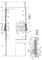
- FIG. 1 illustrates a pipe connection partly in axial section, partly in a view
- FIG. 2 shows a detail thereof, etc. in the sealing area, in section
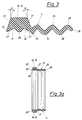
- FIGS. 3 and 3a show the cross section of the sealing ring
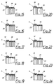
- 4 to 24 show partial axial sections through sealing rings which can be used here
- FIG. 25 gives a further embodiment the pipe connection partly in axial section, partly in view again, the sleeve part between the recess for the sealing ring and the sleeve end being extended compared to the embodiment according to FIG. 1.
- the pipe connection consists of the tip end 1 of the pipe 2 and the end of the pipe 4 widened to the sleeve 3.
- the sleeve 3 has an annular recess at a distance from its end 6.
- This recess 5 has different depths, as can be seen at 7 and 8, for which reference is made particularly to Fig. 2.
- the tubes can be made of plastic, for example polyvinyl chloride, polyethylene, polypropylene, plexiglass, polymethacrylate, polyphenylene oxide, polyphenylene ether or polycarbonate, or of reinforced or fiber or glass fiber reinforced plastic.
- Non-ferrous metals such as aluminum and copper in question.
- the sealing rings themselves can be made of elastomers or the like, which can be thermoplastic or curing, rubber or other elastic plastics. exist, copolymers, polyethylene and the like. come into question. Not only pipes with smooth jackets, but also profiled pipes, especially corrugated pipes, can be provided with the pipe connections described.
- the outer jacket 9 of the tube 2 is continuously cylindrical, with the exception of its pointed end 10.
- the sleeve 3 has in the parts 11 and 12 located next to the recess 6, with the exception of the sleeve neck 13, a cylindrical inner jacket which has the same diameter or the same inner width in these parts 11 and 12.
- the outside diameter of the inserted pipe 2 - at least in the area of the pipe connection - can be 110 mm and the inside diameter of the sleeve in the areas 11 and 12 can be 111 mm.
- This play or the distance between the sleeve inner jacket and the outer jacket of the inserted pipe in the connection area is present even if extreme manufacturing or manufacturing tolerances occur or are permissible, i.e. the smallest diameter of the sleeve inner jacket and the largest outer diameter of the inserted pipe when manufacturing the The aforementioned parts of a pipe connection meet or are present.
- the bottoms of the depression 6, ie here the depression parts 7 and 8, are likewise cylindrical in shape and have, for example, diameters of 115 mm in the area 8 and 124.5 mm in the area 7. These bottoms can also be concave or convex (in cross section) seen) be trained.
- a ratio of approximately or exactly 110: 111 or 11.0: 11.1 is preferred between the outer diameter of the inserted pipe end 1, 2 and the inner diameter of the socket parts 11, 12.
- the sealing ring 5 has a thickened part 18 with a cross section 19 with steep flanks 20, 21, here with an approximately trapezoidal cross section (FIGS. 2, 3!).
- the part 7 of the sleeve recess 6 also has steep flanks 22, 23 and also a trapezoidal cross section, the shape of the sealing ring and the shape of this recess in the region of the sealing ring thickening 18 being adapted to one another, taking into account the deformation occurring during operation.
- a thinner sealing ring part 24 in the form of an approximately cylindrical, or approximately cylindrical, jacket with an undulating cross section.
- the cross section of these waves has an approximately constant thickness.
- three shafts are provided, the shaft 25 furthest from the thickened ring part 18, 19 ending with an inwardly directed branch 25 (FIGS. 2, 3, 3 a!).
- the flank 20, 22 of the thickened sealing part 18, 19 or the recess 7 receiving it is formed longer than the adjacent inner wall 27 of this sealing ring part or as the flank 21, to which the thinner sealing part 24 running approximately axially parallel is connected.
- flanks 20, 21 of the thickened sealing ring part 18, 19 or the flanks 22, 23 of part 7 of the recess 6 with greater depth or the flanks of the trapezoidal cross sections form an angle ⁇ of approximately 20 ° with transverse axial planes (FIG. 2 , 3!). Angles ⁇ between 15 ° and 25 ° are conceivable.
- the recess 6 for the sealing ring 5 is advantageously located closer to the sleeve end, and so on. here at a distance of approximately 50 mm from the socket end, and at a greater distance, here of approximately 80 mm, from the socket neck 13.
- the illustrated embodiment of the sealing ring in connection with its arrangement in the pipe sleeve or with the visible pipe connection results in a particularly good seal in the area of the pipe connection.
- the present multifunctional annular sealing element 5 consists of a wiping lip or cleaning lip 30, a first protective chamber 31 (FIG. 3!), A support and sealing lip 29 already mentioned, a second dirt chamber 32 and four further sealing lips 33, 34, 35 and 26. Due to the specific design of the sealing element 5 with steep trapezoidal flanks 20, 21 in the first third - the flank 20 being extended and thus becoming a cleaning lip 30 - this sealing element is shaped accordingly Sleeve recess 6 held practically immovable, especially since there is considerable frictional engagement in the area of the flanks.
- the waves or ribs 33, 34 and 35 have here the same inner diameter. All shafts shown here also have approximately the same outside diameter.
- the pipe 2 to be inserted or its tip end 1 is first cleaned by the cleaning lip 30 of adhering dirt such as Soil, sand or small rock cleaned.
- the stripped dirt is picked up in front of the cleaning lip 30 in the region of the front flank 20 in the cavity formed by the play between the outer jacket 9 of the pipe 2 and the inner jacket 11 of the sleeve 3.
- the tip end 1 presses this or the thickened sealing ring part 18, 19 into the provided recess 6, 7, 8 in the sleeve 3 or over the sealing and support ring 29 arranged in the central region of the trapezoidal first third of the sealing element 5 in particular against the trapezoidal flanks 22, 23 (flank angle ⁇ between 15 ° and 25 °) in the sleeve 3.
- the pipe sleeve in the area in front of the sealing element is called a long sleeve (Guide length 1), wherein the ratio of the outer tube diameter d to the guide length 1 can be, for example, 0.2, in particular at least 0.4 and at most 1.0.
- the pipe introduced subsequently reaches the second sealing lip 33 - any dirt still adhering to it is deposited in front of it in the second dirt chamber 32 - and stretches the part 24 of the shaft which is equipped with three further sealing lips and is undulating Sealing element in the axial direction towards the sleeve neck 13, whereby the further sealing lips are pressed against the pipe 2.
- This specific design of the multifunctional sealing element or sealing ring 5 allows between the outer tube and Socket inner diameter to provide a larger game than usual, whereby any production tolerances can be bridged easily and the bias of the sealing element against the pipe 2 to be inserted can be reduced, so that the assembly is simple and easy without the help of tools or devices by hand.
- the sleeve guide can be made cylindrical throughout the entire sleeve area, making manufacturing and tooling much easier and cheaper.
- the wide or long design of the seal in combination with the larger play as well as the numerous, here a total of five sealing lips allow greater flexibility of the socket connection despite optimal tightness, which is particularly the case in practice with unavoidable displacements of the central axes of the pipes to be connected due to level differences the pipe trench sole or, depending on the material, possible curvilinear laying is an advantage.
- the ratio of tube diameter d to sealing element length L is advantageously at least 1: 0.2, but should not exceed 1: 0.8 for economic reasons.
- the Shore hardness of the sealing element is of further importance; it should be between a minimum of 40 + 5 and a maximum of 56 + 5 Shore A.
- sealing rings 5 which can be used in the pipe connections described above.
- Axially parallel or cylindrical walls 36 are again provided for the thinner sealing part, on which ribs 37 are present on the inside (FIGS. 5, 12) , Fig. 16).
- Ribs 38 can also be provided on the outside of these walls (FIGS. 4, 6, 7, 8, 9, 11, 14, 15, 17, 18) 19, 20, 22, 24), which can be offset with respect to the ribs 37 (FIGS. 4, 6, 9, 15, 17, 20) ).
- the thickened parts 18 are shaped with an approximately trapezoidal cross section (FIGS. 4 to 12, FIGS.
- the thickened sealing part 18 'with an approximately trapezoidal cross-section was hollowed out on its inside between its flanks and the annular thickening 29 provided here again, which can influence the elasticity or the weight of the sealing ring.
- 13 shows yet another variant of the sealing ring with a thickened ring part 39, the cross section of which deviates from the trapezoidal shape; it is an approximately circular cross section with an extension 40, which again serves as a wiping or cleaning lip.
- This embodiment again has a thinner sealing part 24 with a wavy cross section.
- angular configurations with a zigzag cross section can also be provided according to FIGS. 10 and 21.
- the aforementioned ribs can have a rectangular, triangular or semicircular cross section.
- the inner ribs 37 provided on the thin-walled sealing part or on its wall 36 advantageously have the same inner diameter.
- the ribs 38 provided on the outside of the wall expediently have the same outside diameter.
- the ratio of the length of the socket end part in front of the seal to the diameter of the pipe tip end is advantageously 0.2: 1, in particular at least 0.4: 1.
- An equal amount of play is again provided in the pipe connection area between the pipe outer jacket 9 and the sleeve inner jacket parts 11, 12. whereby naturally in the area of the seal 5 there is a considerably increased play due to the sleeve widening 6 provided for this.
- the ratio of the sealing ring length to the outer pipe diameter is at most 0.8: 1, at least 0.2: 1.
Landscapes
- Engineering & Computer Science (AREA)
- General Engineering & Computer Science (AREA)
- Mechanical Engineering (AREA)
- Physics & Mathematics (AREA)
- Fluid Mechanics (AREA)
- Joints With Sleeves (AREA)
Claims (9)
- Système d'étanchement pour des raccords de tuyaux, en particulier du type enfichage, préférablement pour des tuyaux plastiques ou métalliques, dans lesquels l'extrémité de l'un des tuyaux, qui, à l'exception de l'extrémité appointue, avantageusement a une surface extérieure cylindrique, est introduite dans l'extrémité de l'autre tuyau, évasée pour former un manchon de jonction, cette partie évasée ayant à l'intérieur, à une distance de l'extrémité du manchon, une gorge annulaire de profondeur variable pour la réception d'un anneau d'étanchéité, et ce manchon à côté de la gorge préférablement ayant une surface intérieure cylindrique et l'anneau d'échantéité ayant des domaines d'épaisseur différente, une partie épaissie de l'anneau en particulier de section transversale trapézoidale étant prevue dans son domaine au côté de l'extrémité du manchon et au moins une partie de joint de beaucoup plus faible épaisseur que celle-là étant reliée avec cette partie épaissie de l'anneau d'étanchéité, et le flanc (20) au côté de l'extrémité du manchon de la partie épaissie (18) de l'anneau d'étanchéité étant avancé vers l'intérieur au-delà de la paroi adjacente respective du flanc (22) au côté de l'éxtrémité du manchon de la gorge (7) du tuyau de manchon (3) quand l'anneau d'étanchéité est introduit dans le manchon, caractérisé en ce que la partie épaissie (18) de l'anneau d'étanchéité et cette partie de la gorge annulaire (6) du tuyau de manchon ayant une plus grande profondeur (7) présentent une section transversale avec des flancs (20,21;22,23) formant un angle aigu de 15° à 25°, en particulier 20°, avec des plans transversaux relativement à l'axe, et en ce que le flanc au côté de l'extrémité du manchon de la portion épaissie de l'anneau d'étanchéité est avancé vers l'intérieur au-delà de la paroi intérieure (27) de la partie épaissie de l'anneau d'étanchéité, et en ce que des parties (24) de plus faible épaisseur de l'anneau d'étanchéité, en moyenne étant parallèle à l'axe du tuyau, se joignent au deuxième flanc (21) de la partie épaissie de l'anneau d'étanchéité.
- Système d'étanchement selon la revendication 1, caractérisé en ce qu'un épaississement (29) s'étendant perpendiculairement à l'axe de l'anneau est pourvu à la paroi intérieure de la partie épaissie (18) de l'anneau d'étanchéité, en particulier au centre de la paroi intérieure.
- Système d'étanchement selon la revendication 1 ou la revendication 2, caractérisé en ce que la dureté Shore de tout l'anneau d'étanchéité est entre 35 et 61 Shore A, la matière de l'anneau comme connue en soi préférablement consistant en élastomères, copolymères, matière synthétique élastique respectivement thermodurcissable et thermoplastique, polyéthylène, par exemple en caoutchouc.
- Sytème d'étanchement selon l'une des revendications 1 à 3, caractérisé en ce que la partie de joint (24) de plus faible épaisseur, reliée à la partie épaissie (18) de l'anneau d'étanchéité, présente une bande de section transversale ondulée d'une épaisseur approximativement constante, ayant un cours approximativement parallèle à l'axe, préférablement au moins deux ondulations étant arrangées et appropriément l'extrémité (26) de la dernière ondulation en section transversale (25) étant dirigée vers l'intérieur.
- Système d'étanchement selon l'une des revendications 1 à 4, caractérisé en ce que la partie (36) de plus faible épaisseur de l'anneau d'étanchéité est pourvue de deux ou plusieurs nervures d'étanchéité annulaires (37), dirigées vers l'axe du tuyau, des nervures d'étanchéité (38) dirigées vers l'extérieur et désaxées relativement aux nervures d'étanchéité (37) dirigées vers l'intérieur étant préférablement pourvues aussi.
- Système d'étanchement selon la revendication 4 ou la revendication 5, caractérisé en ce que les diamètres intérieurs respectivement des nervures intérieures (33,34,35,37) et des ondulations, dirigées vers l'intérieur, de la partie (24,36) de plus faible épaisseur de l'anneau d'étanchéité sont approximativment égaux.
- Système d'étanchement selon l'une des revendications 4 à 6, caractérisé en ce que les diamètres extérieurs respectivement des nervures extérieurs (25,38) et des ondulations, dirigées vers l'extérieur, de la partie (24,36) de plus faible épaisseur de l'anneau d'étanchéité sont approximativement égaux.
- Système d'étanchement selon l'une des revendications 4 à 7, caractérisé en ce que le diamètre intérieur de la partie (24,36) de plus faible épaisseur de l'anneau d'étanchéité ou bien des nervures intérieurs de celle-ci ou bien des ondulations dirigées vers l'intérieur de celle-ci est inférieur au diamètre intérieur de la partie épaissie (18) de l'anneau d'étanchéité, en particulier de son flanc au côté de l'extrémité du manchon et/ou de son épaississement annualire au centre de sa paroi intérieure, par exemple le rapport entre ces diamètres intérieurs est 10,5 : 10,9, ce qui, par exemple, resulte en un rapport de 105 à 109 mm au cas d'une hauteur de la partie épaissie (18) de l'anneau d'étanchéité de 15,5 mm.
- Système d'étanchement selon l'une des revendications 1 à 8, caractérisé en ce que la partie épaissie (18) de l'anneau d'étanchéité est creusée au côté dirigé vers l'intérieur entre les flancs (20,21) et l'épaississement annulaire (29).
Priority Applications (1)
| Application Number | Priority Date | Filing Date | Title |
|---|---|---|---|
| DE9090890085T DE59002329D1 (de) | 1990-03-26 | 1990-03-26 | Dichtungsring. |
Applications Claiming Priority (1)
| Application Number | Priority Date | Filing Date | Title |
|---|---|---|---|
| AT250888A AT392146B (de) | 1988-10-11 | 1988-10-11 | Dichtungsring |
Publications (2)
| Publication Number | Publication Date |
|---|---|
| EP0448922A1 EP0448922A1 (fr) | 1991-10-02 |
| EP0448922B1 true EP0448922B1 (fr) | 1993-08-11 |
Family
ID=3535544
Family Applications (1)
| Application Number | Title | Priority Date | Filing Date |
|---|---|---|---|
| EP90890085A Expired - Lifetime EP0448922B1 (fr) | 1988-10-11 | 1990-03-26 | Joint d'étanchéité |
Country Status (2)
| Country | Link |
|---|---|
| EP (1) | EP0448922B1 (fr) |
| AT (1) | AT392146B (fr) |
Families Citing this family (5)
| Publication number | Priority date | Publication date | Assignee | Title |
|---|---|---|---|---|
| DE4108199C2 (de) * | 1991-03-14 | 1995-01-05 | Friatec Keramik Kunststoff | Verbindungsanordnung einer Rohrleitung |
| EP1185479B1 (fr) * | 1999-06-10 | 2003-10-15 | JohnsonDiversey, Inc. | Raccord |
| EP1192101B1 (fr) | 1999-06-10 | 2004-01-21 | JohnsonDiversey, Inc. | Couplage et piston destine a ce couplage |
| EP1840436A1 (fr) * | 2006-03-31 | 2007-10-03 | Hawle Armaturen GmbH | Joint combiné pour un raccord de tuyaux |
| WO2016081590A1 (fr) * | 2014-11-20 | 2016-05-26 | Illinois Tool Works Inc. | Raccord rapide |
Citations (1)
| Publication number | Priority date | Publication date | Assignee | Title |
|---|---|---|---|---|
| US3856315A (en) * | 1973-01-02 | 1974-12-24 | P Stansbury | Bell and spigot pvc pipe joint |
Family Cites Families (11)
| Publication number | Priority date | Publication date | Assignee | Title |
|---|---|---|---|---|
| FR718687A (fr) * | 1931-06-11 | 1932-01-27 | Disposition d'un joint d'étanchéité pour tuyaux de conduite | |
| US3081102A (en) * | 1960-10-03 | 1963-03-12 | Murray Rubber Company Inc | Gasket for telescoping joint |
| US3048415A (en) * | 1960-12-05 | 1962-08-07 | Press Seal Gasket Corp | Pipe joint assembly |
| GB1083451A (en) * | 1963-03-11 | 1967-09-13 | Allied Ironfounders Ltd | A sealing member and a pipe joint incorporating the same |
| BE790773A (fr) * | 1972-03-09 | 1973-02-15 | Amiantit S A L | Joint pour tuyauteries |
| FR2234508A1 (en) * | 1973-06-21 | 1975-01-17 | Bertschmann Hans | Flexible joining seal for tulip ended pipe - has three unequal section rings connected by flexible membranes |
| AT366210B (de) * | 1977-04-05 | 1982-03-25 | Vogelsang Ernst Gmbh Co Kg | Rohrverbinder |
| DE2731749C2 (de) * | 1977-07-14 | 1983-05-19 | Dipl.-Ing. Dr. Ernst Vogelsang Gmbh & Co Kg, 4352 Herten | Rohrverbinder |
| JPS5814311Y2 (ja) * | 1977-11-22 | 1983-03-22 | 株式会社クボタ | 管継手部構造 |
| GB1595172A (en) * | 1977-12-19 | 1981-08-12 | Wavin Bv | Pipe couplings |
| AT379446B (de) * | 1982-11-26 | 1986-01-10 | Technoplast Ges M B H | Steckverbindung |
-
1988
- 1988-10-11 AT AT250888A patent/AT392146B/de not_active IP Right Cessation
-
1990
- 1990-03-26 EP EP90890085A patent/EP0448922B1/fr not_active Expired - Lifetime
Patent Citations (1)
| Publication number | Priority date | Publication date | Assignee | Title |
|---|---|---|---|---|
| US3856315A (en) * | 1973-01-02 | 1974-12-24 | P Stansbury | Bell and spigot pvc pipe joint |
Also Published As
| Publication number | Publication date |
|---|---|
| ATA250888A (de) | 1990-07-15 |
| EP0448922A1 (fr) | 1991-10-02 |
| AT392146B (de) | 1991-01-25 |
Similar Documents
| Publication | Publication Date | Title |
|---|---|---|
| EP0405163B1 (fr) | Tuyaux en matières plastiques pour rénovation de canalisations | |
| EP0231446B1 (fr) | Tuyau ondulé en plastique avec manchon incorporé | |
| DE3879674T2 (de) | Schnellkupplung fuer rohre oder schlaeuche mit einem kegelfoermigen haltering. | |
| EP0638754B1 (fr) | Joint verrouillé à emboîtement | |
| DE69202587T2 (de) | Mehrteilige Manschette, ihr Installationsverfahren und zugehöriges Dichtelement. | |
| EP0448921B1 (fr) | Raccord pour tuyaux | |
| DE1525987A1 (de) | Rohrkupplung | |
| DE2340644A1 (de) | Dichtglied bzw. -ring zur abdichtung einer rohrmuffenverbindung | |
| EP0448922B1 (fr) | Joint d'étanchéité | |
| EP0405245A2 (fr) | Raccord de tuyau flexible pour un tuyau flexible à haute pression | |
| DE69322955T2 (de) | Beschichtungsrohr | |
| DE20017639U1 (de) | Rohr, insbesondere Schutzrohr aus Kunststoff | |
| EP0343677B1 (fr) | Joint d'étanchéité entre deux éléments préfabriqués en béton, insérables l'un dans l'autre | |
| DE3605330A1 (de) | Dichtungsmittel fuer die axiale verbindung quergewellter rohre aus kunststoff | |
| EP0622577A1 (fr) | Raccord de tuyaux avec bague d'étanchéité à coussin d'air | |
| DD252647A5 (de) | Vorrichtung zum verbinden von rohren | |
| DE8214695U1 (de) | Elastischer dichtring | |
| DE10139984A1 (de) | Vorrichtung zur Sicherung einer Rohrverbindung | |
| DE4137495C2 (de) | Rohrverbindung für Druckrohre | |
| DE3540321C2 (fr) | ||
| AT336968B (de) | Dichtungsring fur rohrkupplungen | |
| EP0226743B1 (fr) | Manchon de raccordement pour tuyaux de percement | |
| DE102017106183B4 (de) | Kunststoff-Abgasmuffenrohr sowie Heizungssystem | |
| EP3073165B1 (fr) | Tuyau et piece tubulaire | |
| DE6800630U (de) | Zug- und schubsicherung fuer schraubmuffen-verbindungen. |
Legal Events
| Date | Code | Title | Description |
|---|---|---|---|
| PUAI | Public reference made under article 153(3) epc to a published international application that has entered the european phase |
Free format text: ORIGINAL CODE: 0009012 |
|
| 17P | Request for examination filed |
Effective date: 19901210 |
|
| AK | Designated contracting states |
Kind code of ref document: A1 Designated state(s): BE CH DE DK ES FR GB GR IT LI LU NL SE |
|
| 17Q | First examination report despatched |
Effective date: 19920424 |
|
| GRAA | (expected) grant |
Free format text: ORIGINAL CODE: 0009210 |
|
| AK | Designated contracting states |
Kind code of ref document: B1 Designated state(s): BE CH DE DK ES FR GB GR IT LI LU NL SE |
|
| PG25 | Lapsed in a contracting state [announced via postgrant information from national office to epo] |
Ref country code: IT Free format text: LAPSE BECAUSE OF FAILURE TO SUBMIT A TRANSLATION OF THE DESCRIPTION OR TO PAY THE FEE WITHIN THE PRE;WARNING: LAPSES OF ITALIAN PATENTS WITH EFFECTIVE DATE BEFORE 2007 MAY HAVE OCCURRED AT ANY TIME BEFORE 2007. THE CORRECT EFFECTIVE DATE MAY BE DIFFERENT FROM THE ONE RECORDED.SCRIBED TIME-LIMIT Effective date: 19930811 Ref country code: DK Effective date: 19930811 Ref country code: FR Effective date: 19930811 Ref country code: SE Effective date: 19930811 Ref country code: BE Effective date: 19930811 Ref country code: ES Free format text: THE PATENT HAS BEEN ANNULLED BY A DECISION OF A NATIONAL AUTHORITY Effective date: 19930811 Ref country code: NL Effective date: 19930811 Ref country code: GB Effective date: 19930811 Ref country code: GR Free format text: LAPSE BECAUSE OF FAILURE TO SUBMIT A TRANSLATION OF THE DESCRIPTION OR TO PAY THE FEE WITHIN THE PRESCRIBED TIME-LIMIT Effective date: 19930811 |
|
| REF | Corresponds to: |
Ref document number: 59002329 Country of ref document: DE Date of ref document: 19930916 |
|
| EN | Fr: translation not filed | ||
| NLV1 | Nl: lapsed or annulled due to failure to fulfill the requirements of art. 29p and 29m of the patents act | ||
| GBV | Gb: ep patent (uk) treated as always having been void in accordance with gb section 77(7)/1977 [no translation filed] |
Effective date: 19930811 |
|
| PG25 | Lapsed in a contracting state [announced via postgrant information from national office to epo] |
Ref country code: LU Free format text: LAPSE BECAUSE OF NON-PAYMENT OF DUE FEES Effective date: 19940331 Ref country code: CH Effective date: 19940331 Ref country code: LI Effective date: 19940331 |
|
| PLBE | No opposition filed within time limit |
Free format text: ORIGINAL CODE: 0009261 |
|
| STAA | Information on the status of an ep patent application or granted ep patent |
Free format text: STATUS: NO OPPOSITION FILED WITHIN TIME LIMIT |
|
| 26N | No opposition filed | ||
| REG | Reference to a national code |
Ref country code: CH Ref legal event code: PL |
|
| PG25 | Lapsed in a contracting state [announced via postgrant information from national office to epo] |
Ref country code: DE Effective date: 19941201 |