EP0448949A2 - Broche pour produire un fil - Google Patents
Broche pour produire un fil Download PDFInfo
- Publication number
- EP0448949A2 EP0448949A2 EP91102232A EP91102232A EP0448949A2 EP 0448949 A2 EP0448949 A2 EP 0448949A2 EP 91102232 A EP91102232 A EP 91102232A EP 91102232 A EP91102232 A EP 91102232A EP 0448949 A2 EP0448949 A2 EP 0448949A2
- Authority
- EP
- European Patent Office
- Prior art keywords
- spindle
- thread
- sleeve
- brake
- hollow
- Prior art date
- Legal status (The legal status is an assumption and is not a legal conclusion. Google has not performed a legal analysis and makes no representation as to the accuracy of the status listed.)
- Granted
Links
Images
Classifications
-
- D—TEXTILES; PAPER
- D02—YARNS; MECHANICAL FINISHING OF YARNS OR ROPES; WARPING OR BEAMING
- D02G—CRIMPING OR CURLING FIBRES, FILAMENTS, THREADS, OR YARNS; YARNS OR THREADS
- D02G3/00—Yarns or threads, e.g. fancy yarns; Processes or apparatus for the production thereof, not otherwise provided for
- D02G3/22—Yarns or threads characterised by constructional features, e.g. blending, filament/fibre
- D02G3/26—Yarns or threads characterised by constructional features, e.g. blending, filament/fibre with characteristics dependent on the amount or direction of twist
- D02G3/28—Doubled, plied, or cabled threads
- D02G3/285—Doubled, plied, or cabled threads one yarn running over the feeding spool of another yarn
-
- D—TEXTILES; PAPER
- D01—NATURAL OR MAN-MADE THREADS OR FIBRES; SPINNING
- D01H—SPINNING OR TWISTING
- D01H13/00—Other common constructional features, details or accessories
- D01H13/10—Tension devices
- D01H13/104—Regulating tension by devices acting on running yarn and not associated with supply or take-up devices
- D01H13/106—Regulating tension by devices acting on running yarn and not associated with supply or take-up devices for double-twist spindle
-
- D—TEXTILES; PAPER
- D01—NATURAL OR MAN-MADE THREADS OR FIBRES; SPINNING
- D01H—SPINNING OR TWISTING
- D01H7/00—Spinning or twisting arrangements
- D01H7/02—Spinning or twisting arrangements for imparting permanent twist
- D01H7/04—Spindles
-
- D—TEXTILES; PAPER
- D01—NATURAL OR MAN-MADE THREADS OR FIBRES; SPINNING
- D01H—SPINNING OR TWISTING
- D01H7/00—Spinning or twisting arrangements
- D01H7/02—Spinning or twisting arrangements for imparting permanent twist
- D01H7/88—Hollow-spindle arrangements
Definitions
- the invention relates to a spindle for producing a thread, in particular double-wire twist or a cabling thread, with a spindle rotor having a spindle hollow shaft, a thread storage disk rotating with the spindle rotor, which has a radially extending thread guide channel for the thread which adjoins the spindle hollow shaft a first deflection point between the hollow spindle shaft and the thread guide channel is deflected from an axial movement path into an essentially radial movement path and after exiting the thread guide channel continues to form a thread balloon, with a thread guide arranged in the extension of the spindle axis, which forms a second deflection point for deflecting the thread path from a path of movement having a radial movement component into an essentially axial path of movement, and with at least one the operating mode of the spindle and / or the thread-influencing organ, which lies in the spindle within the thread balloon formed during spindle operation.
- spindles for example, thread brakes, ply-wing brakes, ply-wing arrangements or the like.
- These elements which are important for the running of the thread or the operation of the spindle, are practically beyond the control of the outside during the proper spindle run, or at least such an influence is difficult.
- This is disadvantageous, and measures are desired which make it possible to influence such elements, which are provided, for example, within the stationary delivery bobbin carrier mounted on the spindle, without the need for complicated equipment.
- the invention has for its object to provide a device with which it is possible to influence mechanically from the outside on functional elements or control elements, which are arranged in the area of the delivery bobbin and are enveloped by the thread balloon previously considered impermeable during proper spindle operation.
- the spindle according to the invention is characterized in that in the area of at least one of the two deflection points a sleeve which is coaxial and displaceable in the axial direction and which is at least provided with a lateral opening is arranged on the spindle hollow shaft, and that on the sleeve on the one hand a sleeve actuating element and on the other hand an actuating device for the organ influencing the mode of operation and / or the thread path.
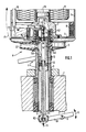
- Fig. 1 shows the solution according to the invention in connection with a cabling spindle A.
- This comprises a hollow spindle whorl or spindle hollow shaft 2 rotatably mounted in a spindle beam 1 in the direction of the arrow f, on the upper end of which a thread storage disk 3 is rotatably attached.
- the protective pot consisting of the protective pot base 4 and the protective pot jacket 5 is supported by means of suitable bearing elements.
- the protective pot is secured against rotation, for example by means of a permanent magnet 6, which interacts with a counter magnet (not shown) arranged outside the spindle.
- a two-armed lever 10 which can be pivoted in the direction of the double arrow f1 about the axis 9 and which has a holder 10.1 located in the extension of the spindle axis for a support tube projecting from below into the hollow spindle whorl or spindle shaft 2 11 carries.
- a sleeve 13 also referred to as a sliding sleeve, is supported by means of an axial bearing 12 and has at least one opening 13.1 in its jacket, preferably in the form of an axially extending longitudinal slot.
- This opening 13.1 is located in the area of the thread storage disk 3 and is directly opposite the radially extending thread guide channel 3.1 of the thread storage disk 3.
- the sleeve 13 is rotatably connected to the spindle whorl or spindle shaft 2, e.g. preferably by means of a pin 14 projecting into an axially extending longitudinal groove 13.2 of the sleeve 13, which is arranged on the inner wall of the spindle whorl or spindle shaft 2.
- a bearing 15 is inserted, which receives a support pin 16 which to a certain extent the bobbin bearing, i.e. the coil pot hub, 4.1 protrudes.
- a two-armed lever 18 which can be pivoted about a horizontal axis 17 is mounted within the bearing block 7.
- the lever 18 carries at its inner end a spherical cap 18.1 with which it is coaxial with the spindle axis on the rounded end attached bolt 16 is supported.
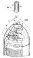
- a hood 20 is placed on the protective jacket 5, which has an opening 20.1 in its upper apex for the thread F2 drawn upwards from the supply spool 8.
- Attached to the inside of the hood 20 is a holder 21 for a thread brake 22 designed in the manner of a lead roller and a thread guide eyelet 23 arranged in the center of the spindle for the thread F2.
- This thread guide eyelet 23 can at the same time contain a thread brake in the form of a ball thread brake, which is represented by the brake ball 23.1 shown in broken lines.
- the main part of the thread brake 22 is preferably designed as a hysteresis dimension with two disc bodies 22.1 and 22.2 which are adjustable relative to one another such that, for example, the braking force of the thread brake 22 can be changed by adjusting the two disc bodies 22.1 and 22.2 relative to one another.
- Pin 26.2 carries. This pin 26.2 engages in an elongated hole opening 24.1 at one end of a double lever 24 which is pivotable about an axis 21.1 attached to the holder 21 and is articulated with its other end to the upper end of the rod 19.
- one thread F1 is fed centrally in the direction of arrow f3 from below through the support tube 11 and the sleeve 13, through the opening 13.1 of which it enters the thread guide channel 3.1; after leaving the thread guide channel 3.1, the thread F1 passes through the thread balloon rotating around the spindle and is combined with the thread F2 drawn upwards from the supply spool 8 just below the balloon thread guide eyelet (not shown) in the so-called cord triangle.
- the threads F1 and F2 combined with one another are then conveyed in the usual manner to a package, not shown, and wound up there.
- the double lever 24 is pivoted about its pivot axis 21.2 via the rod 19 articulated on the double lever 18, which in turn actuates the ratchet element 26 for adjusting the disc body 22.2 of the disc brake 22 relative to the disc body 22.1 via the one-armed pivot lever 26.1.
- the ratchet element 26 By pivoting the ratchet element 26 one or more times, the one disk body 22.2 can be adjusted in each case in a segment-like manner.
- connection is designed as a quick release to simplify the removal of the hood 20 from the bobbin case for removing an empty supply spool and inserting a new supply spool.
- the connection point between the rod 19 and the double lever 24 can also be designed as a fulcrum around which the entire hood 20 including the holder 21 and the elements attached thereto can be pivoted.
- the axial size of the opening 13.1 of the sliding sleeve 13 is so matched to the height of the inner end of the thread guide channel 3.1 that during the axial displacement of the sliding sleeve 13 at least part of the opening 13.1 is aligned with the thread guide channel 3.1.
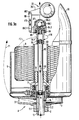
- the bearing 15 inserted into the upper end of the sleeve 13 serves to support a shaft 82 which extends along the spindle axis.
- This shaft 82 is guided through the centering mandrel 7.1 which has a central opening and extends approximately to the upper one Edge of the protective pot casing 5.
- a sleeve 84 which forms a thread guide eyelet, is mounted by means of a bearing 83 and has at least one opening 84.1 in its jacket, preferably in the form of an axially extending longitudinal slot.
- An annular body 84.2 made of abrasion-resistant material is inserted into the upper end of the sleeve 84.
- a ball thread brake is mounted on the top of the sleeve 84 by means of a bearing 85.
- This ball thread brake comprises a cylinder body 86, in which a braking surface ring 86.1 is inserted, on which a braking ball 86.2 rests.
- a cap 87 having a central opening is placed, preferably screwed, on the upper end of the cylinder body 86.
- a holder 86.3 is attached to the outside of the cylinder body 86. On this holder 86.3 one end of a rod 88 is articulated, the other end of which is articulated by means of the axis 88.1 to the single lever 26.1 of the thread brake 22.
- This thread brake 22 with the single lever 26.1 corresponds to the thread brake 22 as described with reference to FIG. 3.
- the thread course of the two threads F1 and F2 corresponds essentially the course of the thread according to the embodiment of FIG. 3 with the modification that the thread F2 drawn off from the supply spool enters laterally through the opening 84.1 into the sleeve 84, which is thereby set in rotation by the thread F2 in the direction of the arrow f10.
- the further path of the thread F2 then corresponds to the course of the thread F2 according to the embodiment of FIG. 3, the thread F2 passing through the thread brake which is formed by the braking surface ring 86.1 and the braking ball 86.2.
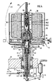
- the double-wire twisting spindle B shown in FIG. 4 comprises in the usual way a hollow spindle whorl or spindle shaft 32, which is rotatably mounted in the spindle beam 31, with which the thread storage disk 33 is rotatably connected and onto which a protective pot, consisting of protective pot base 34 and protective pot jacket, is held in a rotationally fixed manner 35, is attached.
- a hollow shaft 36 is placed coaxially in the extension of the spindle hollow shaft or spindle whorl 32, in the upper end of which the usual thread inlet tube 37 is inserted, into which the thread F3 drawn off from the supply spool 38 inserted into the protective pot runs.
- a bracket 39 On the underside of the spindle beam 31, a bracket 39 is attached, which carries a threaded piece concentric to the spindle axis, preferably in the form of a hollow threaded pin 40.
- a threaded piece preferably in the form of a threaded sleeve 41.1, is screwed onto this threaded pin 40 at its lower end, on which a pivoting lever 41.2 which can be pivoted in the direction of the double arrow f2 and on which an actuating element 42 adjustable in the direction of the double arrow f3 acts.
- a sleeve 44 is supported on the upper end of the support tube 41 by means of an axial bearing 43 and has at least one opening 44.1 in its jacket, preferably in the form of an axially extending longitudinal slot. This opening 44.1 is located in the area of the thread storage disk 33 and is directly opposite the radially running thread guide channel 33.1 of the thread storage disk 33.
- the sleeve 44 is non-rotatably connected to the spindle whorl or spindle shaft 32, by means of a pin 45 projecting into an axially extending longitudinal groove 44.2 of the sleeve 44; which is attached to the inner wall of the spindle whorl or spindle shaft 2.
- a bearing 46 is inserted, which receives a connecting tube 47 which projects to a certain extent above the upper end of the spindle shaft 32.
- An annular lip seal 48 is arranged between the upper end of the spindle shaft 32 and the connecting tube 47.
- a connecting tube 49 running coaxially to the spindle axis, which has an annular shoulder 49.1 approximately in its central region and in the upper end of which a lower braking surface ring 50 is inserted for a brake capsule 51, the upper end of which against an upper one Brake surface ring 52 abuts, which is inserted into the lower end of the thread inlet tube 37.
- the lower brake surface ring 50 is elastically supported by a helical compression spring 53, which in turn is supported on the annular shoulder 49.1 of the connecting pipe 49.
- a guide tube 50.1 is fastened, which is guided through the opening formed by the annular shoulder 49.1 and below the annular shoulder 49.1 carries a piston 50.2 displaceable in the lower part of the connecting tube 49.
- This piston 50.2 is provided on its underside with support cams 50.3, of which the piston 50.2 is supported on the top of the connecting tube 47 when it is moved downward against the force of the spring 53.
- a compressed air duct 54 leads through the jacket of the spindle hollow axis 36 and the protective pot base 34, the outer end of which lies on the outer edge of the protective pot base 34, such that that an adjustable in the direction of the double arrow f5 compressed air connection 55 can be inserted into the compressed air channel 54.
- the arrangement described last serves for the pneumatic threading of a thread f3 drawn off from the supply spool 38. If compressed air is blown into the space between the piston 50.2 and the annular shoulder 49.1 by means of the compressed air connection 55, the piston is moved down together with the guide tube 50.1 and the lower brake surface ring 50 against the force of the return spring 43 until the piston 50.2 moves with it Support cams 50.3 supported on the top of the connecting tube 47. The downward movement of the lower brake surface ring 50 releases the brake capsule 51, which has an upper radially outwardly thickened head part, so that the brake capsule 51 can be held by radially inwardly directed support fingers 56 which are attached to the inner circumference of the spindle hollow axis 36.
- the piston 50.2 is not sealingly guided in the connecting tube 49, so that the Compressed air acting on the top of the piston can flow laterally past the piston downward into the connecting tube 47. As a result, a negative pressure is generated in the interior of the guide tube 50. 1, which continues up to the upper end of the thread inlet tube 37. A thread held at the upper end of the thread inlet tube 37 can thereby be gripped by the suction flow and can be conveyed laterally past the brake capsule 51 through the guide tube 50.1, the connecting tube 47, the sleeve 44 and then through the thread guide channel 33.1 of the thread storage disk 33.
- the compressed air supply into the compressed air channel 54 is interrupted, so that the lower brake surface ring 50 is adjusted upwards again under the influence of the return spring 53, such that the brake capsule 51 then again between the two brake surface rings 50 and 52 is supported.
- the support tube 41 is adjusted in the axial direction upwards or downwards by rotating it , whereby the sliding sleeve 44 is axially displaced. Since the sliding sleeve is directly coupled to the lower brake surface ring 50 via the connecting tube 47 and the connecting tube 49, the upward direction thereof Movement is limited by an inwardly projecting annular shoulder of the connecting tube 49, the lower brake surface ring 50 can also be adjusted by axially adjusting the support tube 41, which has a direct influence on the braking force applied by the thread brake 50, 51, 52 and acting on the thread F3 Has.
- the brake capsule 51 also consists of two telescoping parts, between which a compression spring is supported
- the double-wire twisting spindle shown in Fig. 4 is equipped with a thread clamping device.
- This consists of a rod 57 guided through the support tube 41, which carries at its upper end a head piece 57.1, which is positioned just below the inner opening of the thread guide channel 53.1 in the idle state.
- the lower end of the rod 57 is supported on one end of a double lever 58, on the second end of which a pressure cylinder 59 acts in the direction of the double arrow f4.
- the pressure cylinder 59 is activated by a corresponding switching signal of the thread button, such that under the action of the double lever 58, the rod 57 with its head piece 57.1 upwards against a clamping surface through the lower end of the connecting tube 47 is formed, whereby the thread is clamped.
- the axial size of the opening 44.1 of the sliding sleeve 44 is so matched to the height of the inner end of the thread guide channel 33.1 that during the axial displacement of the sliding sleeve 33 at least part of the opening 44.1 is aligned with the thread guide channel 33.1.
Landscapes
- Engineering & Computer Science (AREA)
- Mechanical Engineering (AREA)
- Textile Engineering (AREA)
- Spinning Or Twisting Of Yarns (AREA)
- Mechanically-Actuated Valves (AREA)
Applications Claiming Priority (2)
| Application Number | Priority Date | Filing Date | Title |
|---|---|---|---|
| DE4010017 | 1990-03-29 | ||
| DE4010017A DE4010017C2 (de) | 1990-03-29 | 1990-03-29 | Spindel zum Herstellen eines Fadens |
Publications (3)
| Publication Number | Publication Date |
|---|---|
| EP0448949A2 true EP0448949A2 (fr) | 1991-10-02 |
| EP0448949A3 EP0448949A3 (en) | 1991-11-27 |
| EP0448949B1 EP0448949B1 (fr) | 1994-12-28 |
Family
ID=6403274
Family Applications (1)
| Application Number | Title | Priority Date | Filing Date |
|---|---|---|---|
| EP91102232A Expired - Lifetime EP0448949B1 (fr) | 1990-03-29 | 1991-02-18 | Broche pour produire un fil |
Country Status (6)
| Country | Link |
|---|---|
| US (1) | US5150566A (fr) |
| EP (1) | EP0448949B1 (fr) |
| JP (1) | JP2994477B2 (fr) |
| CZ (1) | CZ279949B6 (fr) |
| DE (1) | DE4010017C2 (fr) |
| ES (1) | ES2066242T3 (fr) |
Cited By (2)
| Publication number | Priority date | Publication date | Assignee | Title |
|---|---|---|---|---|
| EP0620301A1 (fr) * | 1993-04-13 | 1994-10-19 | Palitex Project-Company GmbH | Dispositif de réglage de freins de fil à capsule sur métiers à retordre, en particulier pour métiers à retordre à double torsion |
| FR2739400A1 (fr) * | 1995-10-02 | 1997-04-04 | Temco Textilmaschkomponent | Broche d'enroulement pour machines textiles |
Families Citing this family (9)
| Publication number | Priority date | Publication date | Assignee | Title |
|---|---|---|---|---|
| US5706642A (en) * | 1996-10-08 | 1998-01-13 | Haselwander; Jack G. | Variable twist level yarn |
| IT1295565B1 (it) * | 1997-06-05 | 1999-05-13 | Agnolo Armando D | Fuso per torsioni multiple |
| US7299615B2 (en) * | 2004-06-18 | 2007-11-27 | Mannington Mills, Inc. | Variable twist level yarn using fluid twisting |
| US7288306B2 (en) * | 2004-08-25 | 2007-10-30 | Mannington Mills, Inc. | Textile substrate having low variable twist yarn |
| US7500345B2 (en) * | 2006-11-07 | 2009-03-10 | The Goodyear Tire & Rubber Company | Mandrel for a tubular strander |
| JP2012001857A (ja) * | 2010-06-18 | 2012-01-05 | Murata Mach Ltd | 合撚糸機、および合撚糸機を使った合撚糸の製造方法 |
| DE102015005447A1 (de) * | 2015-04-28 | 2016-11-03 | Saurer Germany Gmbh & Co. Kg | Verfahren zum Betreiben einer Spindel einer Doppeldrahtzwirn- oder Kabliermaschine sowie zugehörige Doppeldrahtzwirn- oder Kabliermaschine |
| DE102019105072A1 (de) * | 2019-02-28 | 2020-09-03 | Saurer Technologies GmbH & Co. KG | Spulentopflagerung |
| CN116271446A (zh) * | 2023-01-31 | 2023-06-23 | 中国人民解放军陆军军医大学第一附属医院 | 一种双腔支撑球囊导管 |
Family Cites Families (15)
| Publication number | Priority date | Publication date | Assignee | Title |
|---|---|---|---|---|
| US2870596A (en) * | 1957-09-04 | 1959-01-27 | Alfred W Vibber | Twisting spindle balloon control |
| BE636081A (fr) * | 1962-08-14 | |||
| US3286450A (en) * | 1964-06-22 | 1966-11-22 | Alfred W Vibber | Apparatus for twisting and plying strands |
| DE1510853B1 (de) * | 1965-07-16 | 1970-08-20 | Palitex Project Co Gmbh | Vorrichtung an einer Doppeldraht-Zwirnspindel zum Steuern von Fadenbremsen od.dgl. |
| DE1510854B1 (de) * | 1965-08-06 | 1970-07-09 | Palitex Project Co Gmbh | Mehrfachdrahtzwirn- oder -spinnspindel |
| US3410017A (en) * | 1966-06-02 | 1968-11-12 | Robert L. Wilson | Fishing rod grip |
| US3406511A (en) * | 1967-07-27 | 1968-10-22 | Palitex Project Co Gmbh | Two-for-one twisting spindle with interior winding-up of the thread |
| DE2258183A1 (de) * | 1972-03-27 | 1973-10-04 | Erhard Rinnelt | Verfahren und vorrichtung zum behandeln endloser faeden |
| DE2246174C3 (de) * | 1972-09-20 | 1975-11-20 | Hamel Gmbh Zwirnmaschinen, 4400 Muenster | Rotor einer Doppeldrahtzwirnspindel zur Aufnahme eines frei drehbaren Spulenträgers |
| DE2628125C3 (de) * | 1976-06-23 | 1979-03-08 | Palitex Project-Company Gmbh, 4150 Krefeld | Spinn- oder Zwirnmaschine |
| US4355500A (en) * | 1979-07-23 | 1982-10-26 | Murata Kikai Kabushiki Kaisha | Pneumatic yarn guiding apparatus for double twisting machine |
| DE3611735C2 (de) * | 1985-06-07 | 1996-07-25 | Barmag Barmer Maschf | Kordierspindel |
| US4605182A (en) * | 1985-09-20 | 1986-08-12 | Otto Zollinger, Inc. | Yarn tension control device |
| US4848078A (en) * | 1988-07-05 | 1989-07-18 | White Frances H | Flyer for textile apparatus |
| EP0620301B1 (fr) | 1993-04-13 | 1997-06-18 | Palitex Project-Company GmbH | Dispositif de réglage de freins de fil à capsule sur métiers à retordre, en particulier pour métiers à retordre à double torsion |
-
1990
- 1990-03-29 DE DE4010017A patent/DE4010017C2/de not_active Expired - Fee Related
-
1991
- 1991-02-18 ES ES91102232T patent/ES2066242T3/es not_active Expired - Lifetime
- 1991-02-18 EP EP91102232A patent/EP0448949B1/fr not_active Expired - Lifetime
- 1991-03-20 JP JP3055220A patent/JP2994477B2/ja not_active Expired - Lifetime
- 1991-03-20 CZ CS91746A patent/CZ279949B6/cs unknown
- 1991-03-25 US US07/674,676 patent/US5150566A/en not_active Expired - Fee Related
Cited By (2)
| Publication number | Priority date | Publication date | Assignee | Title |
|---|---|---|---|---|
| EP0620301A1 (fr) * | 1993-04-13 | 1994-10-19 | Palitex Project-Company GmbH | Dispositif de réglage de freins de fil à capsule sur métiers à retordre, en particulier pour métiers à retordre à double torsion |
| FR2739400A1 (fr) * | 1995-10-02 | 1997-04-04 | Temco Textilmaschkomponent | Broche d'enroulement pour machines textiles |
Also Published As
| Publication number | Publication date |
|---|---|
| ES2066242T3 (es) | 1995-03-01 |
| EP0448949A3 (en) | 1991-11-27 |
| JP2994477B2 (ja) | 1999-12-27 |
| US5150566A (en) | 1992-09-29 |
| CZ279949B6 (cs) | 1995-09-13 |
| JPH04214427A (ja) | 1992-08-05 |
| DE4010017C2 (de) | 1994-04-14 |
| EP0448949B1 (fr) | 1994-12-28 |
| CS9100746A2 (en) | 1991-11-12 |
| DE4010017A1 (de) | 1991-10-02 |
Similar Documents
| Publication | Publication Date | Title |
|---|---|---|
| DE69132780T2 (de) | Garnliefervorrichtung | |
| EP0659918B1 (fr) | Dispositif fournisseur de fil | |
| EP0448949B1 (fr) | Broche pour produire un fil | |
| CH643211A5 (de) | Fadenbremse und mit einer derartigen fadenbremse ausgeruestete doppeldraht-zwirnspindel. | |
| DE2050490B2 (de) | Mehrstufige fadenbremsvorrichtung an einer doppeldrahtzwirnspindel | |
| DE2646921C2 (de) | Doppeldrahtzwirnmaschine | |
| CH658870A5 (de) | Doppeldraht-zwirnspindel. | |
| EP0620301B1 (fr) | Dispositif de réglage de freins de fil à capsule sur métiers à retordre, en particulier pour métiers à retordre à double torsion | |
| DE4103286C2 (de) | Doppeldraht-Zwirnspindel | |
| DE4307685C1 (de) | Verfahren zum Aufbau einer Fadenreserve an einem rotierenden Ballonbegrenzer einer Mehrfachdraht-Zwirnspindel und Mehrfachdraht-Zwirnspindel mit rotierendem Ballonbegrenzer | |
| DE3310438C2 (de) | Vorrichtung zur Veränderung des Durchmessers einer Ablaufhilfe für den Überkopfabzug eines auf eine Aufwickelspule aufzuwickelnden Fadens von einer Vorlagespule | |
| DE4010019A1 (de) | Spindel zum herstellen eines fadens | |
| EP0031843B2 (fr) | Flyer pour banc a broches | |
| DE4010018C2 (de) | Spindel zum Herstellen eines Fadens | |
| DE3243157A1 (de) | Fadenbremse mit zugeordneter druckluftbetaetigter einfaedelvorrichtung, insbesondere fuer doppeldraht-zwirnspindeln | |
| DE4404555C1 (de) | Verfahren zum getrennten Einfädeln von zwei von zwei gleichachsig übereinander angeordneten Vorlagespulen abgezogenen Einzelfäden in die zweigeteilte Hohlachse einer Doppeldraht-Zwirnspindel und Doppeldraht-Zwirnspindel | |
| EP0223926A1 (fr) | Procédé et dispositif pour rattacher un fil dans un métier à filer | |
| DE19540790C1 (de) | Zwirnspindel, insbesondere für eine mehrere Zwirnspindeln aufweisende Doppeldraht-Zwirnmaschine | |
| DE2756504C3 (de) | Doppeldraht-Zwirnspindel mit aus einer Druckluftquelle betätigter Einfädelvorrichtung | |
| EP0464424B1 (fr) | Procédé pour réguler automatiquement la force de freinage d'un frein de fil situé dans la broche creuse d'une broche à retordre à double torsion et broche à retordre à double torsion équipée d'un tel frein de fil | |
| DE10324653B4 (de) | Kabliermaschine und Kablierverfahren | |
| DE2718351C2 (de) | Doppeldrahtzwirnspindel mit druckluftbetätigter Einfädelvorrichtung | |
| DE1510847C3 (de) | Federnd nachgiebige Fadenbremse | |
| EP3165640B1 (fr) | Frein de fil de bobine pour une broche de retordage à double torsion | |
| DE2717228C3 (de) | Ringspinn- oder Ringzwirnmaschine zum Herstellen zylindrischer Scheibenspulen |
Legal Events
| Date | Code | Title | Description |
|---|---|---|---|
| PUAI | Public reference made under article 153(3) epc to a published international application that has entered the european phase |
Free format text: ORIGINAL CODE: 0009012 |
|
| AK | Designated contracting states |
Kind code of ref document: A2 Designated state(s): DE ES FR GB IT |
|
| PUAL | Search report despatched |
Free format text: ORIGINAL CODE: 0009013 |
|
| AK | Designated contracting states |
Kind code of ref document: A3 Designated state(s): DE ES FR GB IT |
|
| 17P | Request for examination filed |
Effective date: 19920520 |
|
| 17Q | First examination report despatched |
Effective date: 19931014 |
|
| ITF | It: translation for a ep patent filed | ||
| GRAA | (expected) grant |
Free format text: ORIGINAL CODE: 0009210 |
|
| RBV | Designated contracting states (corrected) |
Designated state(s): ES FR GB IT |
|
| REG | Reference to a national code |
Ref country code: DE Ref legal event code: 8566 |
|
| AK | Designated contracting states |
Kind code of ref document: B1 Designated state(s): ES FR GB IT |
|
| GBT | Gb: translation of ep patent filed (gb section 77(6)(a)/1977) |
Effective date: 19950123 |
|
| REG | Reference to a national code |
Ref country code: ES Ref legal event code: FG2A Ref document number: 2066242 Country of ref document: ES Kind code of ref document: T3 |
|
| ET | Fr: translation filed | ||
| PLBE | No opposition filed within time limit |
Free format text: ORIGINAL CODE: 0009261 |
|
| STAA | Information on the status of an ep patent application or granted ep patent |
Free format text: STATUS: NO OPPOSITION FILED WITHIN TIME LIMIT |
|
| 26N | No opposition filed | ||
| PGFP | Annual fee paid to national office [announced via postgrant information from national office to epo] |
Ref country code: ES Payment date: 19960227 Year of fee payment: 6 |
|
| PG25 | Lapsed in a contracting state [announced via postgrant information from national office to epo] |
Ref country code: ES Free format text: LAPSE BECAUSE OF EXPIRATION OF PROTECTION Effective date: 19970219 |
|
| REG | Reference to a national code |
Ref country code: ES Ref legal event code: FD2A Effective date: 19990601 |
|
| PGFP | Annual fee paid to national office [announced via postgrant information from national office to epo] |
Ref country code: GB Payment date: 20010125 Year of fee payment: 11 |
|
| PGFP | Annual fee paid to national office [announced via postgrant information from national office to epo] |
Ref country code: FR Payment date: 20010222 Year of fee payment: 11 |
|
| REG | Reference to a national code |
Ref country code: GB Ref legal event code: IF02 |
|
| PG25 | Lapsed in a contracting state [announced via postgrant information from national office to epo] |
Ref country code: GB Free format text: LAPSE BECAUSE OF NON-PAYMENT OF DUE FEES Effective date: 20020218 |
|
| GBPC | Gb: european patent ceased through non-payment of renewal fee |
Effective date: 20020218 |
|
| PG25 | Lapsed in a contracting state [announced via postgrant information from national office to epo] |
Ref country code: FR Free format text: LAPSE BECAUSE OF NON-PAYMENT OF DUE FEES Effective date: 20021031 |
|
| REG | Reference to a national code |
Ref country code: FR Ref legal event code: ST |
|
| PG25 | Lapsed in a contracting state [announced via postgrant information from national office to epo] |
Ref country code: IT Free format text: LAPSE BECAUSE OF NON-PAYMENT OF DUE FEES;WARNING: LAPSES OF ITALIAN PATENTS WITH EFFECTIVE DATE BEFORE 2007 MAY HAVE OCCURRED AT ANY TIME BEFORE 2007. THE CORRECT EFFECTIVE DATE MAY BE DIFFERENT FROM THE ONE RECORDED. Effective date: 20050218 |