EP0448954A1 - Anordnung zum Füllen und Abzapfen von Anästhesiemittel - Google Patents
Anordnung zum Füllen und Abzapfen von Anästhesiemittel Download PDFInfo
- Publication number
- EP0448954A1 EP0448954A1 EP91102348A EP91102348A EP0448954A1 EP 0448954 A1 EP0448954 A1 EP 0448954A1 EP 91102348 A EP91102348 A EP 91102348A EP 91102348 A EP91102348 A EP 91102348A EP 0448954 A1 EP0448954 A1 EP 0448954A1
- Authority
- EP
- European Patent Office
- Prior art keywords
- anesthetic
- channels
- articulated arm
- articulated
- channel
- Prior art date
- Legal status (The legal status is an assumption and is not a legal conclusion. Google has not performed a legal analysis and makes no representation as to the accuracy of the status listed.)
- Granted
Links
- 230000003444 anaesthetic effect Effects 0.000 title claims abstract description 45
- 238000010079 rubber tapping Methods 0.000 claims description 7
- 239000003193 general anesthetic agent Substances 0.000 description 4
- 241001411320 Eriogonum inflatum Species 0.000 description 1
- 229940035674 anesthetics Drugs 0.000 description 1
- POIUWJQBRNEFGX-XAMSXPGMSA-N cathelicidin Chemical compound C([C@@H](C(=O)N[C@@H](CCCNC(N)=N)C(=O)N[C@@H](CCCCN)C(=O)N[C@@H](CO)C(=O)N[C@@H](CCCCN)C(=O)N[C@@H](CCC(O)=O)C(=O)N[C@@H](CCCCN)C(=O)N[C@@H]([C@@H](C)CC)C(=O)NCC(=O)N[C@@H](CCCCN)C(=O)N[C@@H](CCC(O)=O)C(=O)N[C@@H](CC=1C=CC=CC=1)C(=O)N[C@@H](CCCCN)C(=O)N[C@@H](CCCNC(N)=N)C(=O)N[C@@H]([C@@H](C)CC)C(=O)N[C@@H](C(C)C)C(=O)N[C@@H](CCC(N)=O)C(=O)N[C@@H](CCCNC(N)=N)C(=O)N[C@@H]([C@@H](C)CC)C(=O)N[C@@H](CCCCN)C(=O)N[C@@H](CC(O)=O)C(=O)N[C@@H](CC=1C=CC=CC=1)C(=O)N[C@@H](CC(C)C)C(=O)N[C@@H](CCCNC(N)=N)C(=O)N[C@@H](CC(N)=O)C(=O)N[C@@H](CC(C)C)C(=O)N[C@@H](C(C)C)C(=O)N1[C@@H](CCC1)C(=O)N[C@@H](CCCNC(N)=N)C(=O)N[C@@H]([C@@H](C)O)C(=O)N[C@@H](CCC(O)=O)C(=O)N[C@@H](CO)C(O)=O)NC(=O)[C@H](CC=1C=CC=CC=1)NC(=O)[C@H](CC(O)=O)NC(=O)CNC(=O)[C@H](CC(C)C)NC(=O)[C@@H](N)CC(C)C)C1=CC=CC=C1 POIUWJQBRNEFGX-XAMSXPGMSA-N 0.000 description 1
- 239000012530 fluid Substances 0.000 description 1
- 239000007788 liquid Substances 0.000 description 1
- 230000001105 regulatory effect Effects 0.000 description 1
Images



Classifications
-
- A—HUMAN NECESSITIES
- A61—MEDICAL OR VETERINARY SCIENCE; HYGIENE
- A61M—DEVICES FOR INTRODUCING MEDIA INTO, OR ONTO, THE BODY; DEVICES FOR TRANSDUCING BODY MEDIA OR FOR TAKING MEDIA FROM THE BODY; DEVICES FOR PRODUCING OR ENDING SLEEP OR STUPOR
- A61M16/00—Devices for influencing the respiratory system of patients by gas treatment, e.g. ventilators; Tracheal tubes
- A61M16/10—Preparation of respiratory gases or vapours
- A61M16/14—Preparation of respiratory gases or vapours by mixing different fluids, one of them being in a liquid phase
- A61M16/18—Vaporising devices for anaesthetic preparations
- A61M16/183—Filling systems
-
- Y—GENERAL TAGGING OF NEW TECHNOLOGICAL DEVELOPMENTS; GENERAL TAGGING OF CROSS-SECTIONAL TECHNOLOGIES SPANNING OVER SEVERAL SECTIONS OF THE IPC; TECHNICAL SUBJECTS COVERED BY FORMER USPC CROSS-REFERENCE ART COLLECTIONS [XRACs] AND DIGESTS
- Y10—TECHNICAL SUBJECTS COVERED BY FORMER USPC
- Y10T—TECHNICAL SUBJECTS COVERED BY FORMER US CLASSIFICATION
- Y10T137/00—Fluid handling
- Y10T137/8593—Systems
- Y10T137/86493—Multi-way valve unit
- Y10T137/86558—Plural noncommunicating flow paths
-
- Y—GENERAL TAGGING OF NEW TECHNOLOGICAL DEVELOPMENTS; GENERAL TAGGING OF CROSS-SECTIONAL TECHNOLOGIES SPANNING OVER SEVERAL SECTIONS OF THE IPC; TECHNICAL SUBJECTS COVERED BY FORMER USPC CROSS-REFERENCE ART COLLECTIONS [XRACs] AND DIGESTS
- Y10—TECHNICAL SUBJECTS COVERED BY FORMER USPC
- Y10T—TECHNICAL SUBJECTS COVERED BY FORMER US CLASSIFICATION
- Y10T137/00—Fluid handling
- Y10T137/8593—Systems
- Y10T137/8807—Articulated or swinging flow conduit
- Y10T137/88078—Actuates valve
- Y10T137/88102—Rotary valve
Definitions
- the invention relates to an arrangement for filling an anesthetic gasifier with anesthetic from a container or tapping anesthetic from the anesthetic gasifier into the container with a connecting part, which has a channel for anesthetic and a channel for air.
- the connecting part of the arrangement consists of a plastic tube in which the channels mentioned run.
- One end of the plastic tube is provided with a bottle cap to which a bottle with anesthetic is attached.
- the other end of the tube has a part for connection to the anesthetic gasifier. Since this arrangement does not have a valve for regulating the anesthetic agent flow when filling or dispensing, the anesthetic gasifier must not be filled or emptied in the operating room, since there is a risk of the anesthetic agent escaping. This is done under a deduction outside the operating room. In addition, due to the structure of the arrangement, the surgeon must hold the bottle in the correct position when filling or tapping.
- the invention has for its object to provide an arrangement of the type mentioned in which filling or emptying an anesthetic gasifier can be carried out without the risk of anesthetic escaping.
- the arrangement should be constructed so that the filling or tapping of the anesthetic gasifier is made easier for the operator.
- the connecting part consists of a first and a second articulated arm, both of them against one another via a joint are pivotally connected, wherein both articulated arms are each provided with two channels and the channels of the first articulated arm can be connected to the channels of the second articulated arm when the articulated arms are brought into specific angular positions to one another. Due to the structure of the connecting part, this also forms a valve that opens or closes the channel connections depending on the angular positions of the articulated arms. This is used when filling and emptying an anesthetic gasifier. This can prevent anesthetic agents from escaping.
- the joint of the articulated arms is formed from their ends, which have overlap parts which are provided with contact surfaces, by means of which the overlap parts are pivotably fastened to one another, and that one end of each channel of the articulated arms in the each contact surface opens, wherein said channel ends of the first articulated arm can be connected to those of the second articulated arm by grooves which are arranged in the overlap part of the one articulated arm.
- the articulated arms of the connecting part can be placed in certain fixed positions, e.g. be brought into a filling or tapping position or in a closed position. This means that the operator does not have to hold the bottle in these positions.
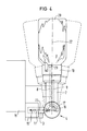
- FIG. 1 shows an arrangement for filling a device shown in FIG. 2 to 5 shown anesthetic gasifier with anesthetic from one of the same in the FIG. 2 to 5 shown bottle or for tapping anesthetics from the anesthetic gasifier into the bottle.
- the arrangement consists of a connecting part 1 with a first articulated arm 2 and with a second articulated arm 3, which are pivotally connected to one another in a joint 4 by means of an axis 5 with a flange and a nut 6.
- the axis 5 is attached along the center line 7 of the joint 4.
- the hinge 4 consists of the ends of the hinge arms 2, 3 which form overlap parts 12, 13, which are provided with contact surfaces 14, 15.
- the articulated arms 2 and 3 are each provided with two channels 8.9 and 10.11.
- the channels 8 and 10 serve as air channels and the channels 9 and 11 serve as anesthetic channels.
- One end of each channel 10, 11 of the articulated arm 3 opens into its contact surface 14.
- the other ends open in the region of the free end of the articulated arm 3.
- One end of each channel 8, 9 of the articulated arm 2 opens into a groove 16, 17 in the Overlap part 12 of the articulated arm 2 are arranged.
- the other ends of the channels 8, 9 open into a bottle closure 18 which is connected to the free end of the articulated arm 2.
- FIG. 2 shows that the grooves 16, 17 are curved in a circle and are arranged concentrically around the axis 5 of the joint 4.
- the grooves 16, 17 are provided in such a way that the channels 8, 10 and 9, 11 of the articulated arms 2, 3 are not connected to one another when the articulated arms 2, 3 are brought into a position in which their central axes 22, 23 are aligned.
- FIG. 3 shows that when connecting the connecting part 1 or the bottle 20 to the anesthetic gasifier 19, the connecting part 1 is brought into a position in which the liquid connection between the bottle 20 and the anesthetic gasifier 19 is interrupted. In this way, no anesthetic can escape in the connecting bevel.
- a check valve is arranged, which prevents anesthetic from entering the air channel.
- the bottle 20 can also be pivoted somewhat in its vertical position about the joint 4 without the connection between the channels of the articulated arms 2 and 3 being interrupted. The pivoting is represented by the dashed contours.
- the articulated arm 2 or the bottle 20 When the anesthetic is drawn from the anesthetic gasifier 19, shown in FIG. 5, the articulated arm 2 or the bottle 20 is pivoted about the articulation 4 into a vertical position, with the opening of the bottle pointing upwards. Due to this position, the articulated arm has taken such a position that the mouths of the channels 10, 11 of the joint arm 3 lie exactly in front of the grooves 16, 17, so that a connection between the channels 8, 9 of the articulated arm 2 and the channels 10, 11 the Gelekarmes 3 is made. As a result, the anesthetic can flow from the anesthetic gasifier 19 through the channel 11 of the articulated arm 3 via the groove 16 and through the channel 9 of the articulated arm 3 to the bottle 20. In this position too, the bottle 20 can be pivoted somewhat about the joint 4 without the connection between the channels 11 and 19 being interrupted.
Landscapes
- Health & Medical Sciences (AREA)
- Anesthesiology (AREA)
- Life Sciences & Earth Sciences (AREA)
- Animal Behavior & Ethology (AREA)
- Engineering & Computer Science (AREA)
- Biomedical Technology (AREA)
- Heart & Thoracic Surgery (AREA)
- Hematology (AREA)
- Emergency Medicine (AREA)
- Pulmonology (AREA)
- General Health & Medical Sciences (AREA)
- Public Health (AREA)
- Veterinary Medicine (AREA)
- Filling Or Discharging Of Gas Storage Vessels (AREA)
- Closures For Containers (AREA)
- Containers And Packaging Bodies Having A Special Means To Remove Contents (AREA)
- Medicines Containing Material From Animals Or Micro-Organisms (AREA)
Abstract
Description
- Die Erfindung bezieht sich auf eine Anordnung zum Füllen eines Narkosemittelvergasers mit Anästhesiemittel von einem Behälter bzw. Abzapfen von Anästhesiemittel aus dem Narkosemittelvergaser in den Behälter mit einem Verbindungsteil, das einen Kanal für Anästhesiemittel und einen Kanal für Luft aufweist.
- Eine Anordnung dieser Art ist durch die GB-PS 1 394 216 bekannt. Das Verbindungsteil der Anordnung besteht aus einem Kunststoffschlauch, in dem die erwähnten Kanäle verlaufen. Das eine Ende des Kunststoffschlauches ist mit einem Flaschenverschluß versehen, an den eine Flasche mit Anästhesiemittel angeschlossen wird. Das andere Ende des Schlauches weist ein Teil für den Anschluß an den Narkosemittelvergaser auf. Da diese Anordnung kein Ventil zur Regelung des Anesthesiemittelflußes beim Füllen bzw` Abzapfen besitzt, darf der Narkosemittelvergaser nicht in dem Operationsraum gefüllt bzw. entleert werden, da das Risiko eines Entweichens des Anästhesiemittels besteht. Dies erfolgt daher unter einem Abzug außerhalb des Operationsraumes. Außerdem muß der Operateur aufgrund des Aufbaus der Anordnung die Flasche beim Füllen bzw Abzapfen in der richtigen Lage halten.
- Der Erfindung liegt die Aufgabe zugrunde, eine Anordnung der eingangs genannten Art zu schaffen, bei der ein Füllen bzw Entleeren eines Narkosemittelvergasers ohne das Risiko eines Entweichens von Anästhesiemittel erfolgen kann. Außerdem soll die Anordnung so aufgebaut sein, daß das Füllen bzw. Abzapfen des Narkosemittelvergasers für den Operateur erleichtert wird.
- Diese Aufgabe ist erfindungsgemäß dadurch gelöst, daß das Verbindungsteil aus einem ersten und einem zweiten Gelenkarm besteht, die beide über ein Gelenk gegeneinander schwenkbar verbunden sind, wobei beide Gelenkarme mit jeweils zwei Kanälen versehen sind und wobei die Kanäle des ersten Gelenkarmes mit den Kanälen des zweiten Gelenkarmes verbindbar sind, wenn die Gelenkarme in bestimmte Winkellagen zueinander gebracht werden. Durch den Aufbau des Verbindungsteils bildet dieses gleichzeitig ein Ventil, das die Kanalverbindungen abhängig von den Winkellagen der Gelenkarme zueinander öffnet bzw. schließt. Das wird beim Füllen und Entleeren eines Narkosemittelvergasers benützt. Hierdurch kann ein Entweichen von Anästhesiemittel vermieden werden.
- In einer vorteilhaften Ausbildung der Erfindung wird vorgeschlagen, daß das Gelenk der Gelenkarme aus deren Enden gebildet ist, die Überlappungsteile aufweisen, die mit Anlageflächen versehen sind, über welche die Überlappungsteile gegeneinander schwenkbar befestigt sind, und daß das eine Ende jedes Kanales der Gelenkarme in der jeweiligen Anlagefläche mündet, wobei die genannten Kanalenden des ersten Gelenkarmes mit denen des zweiten Gelenkarmes durch Nuten verbindbar sind, die im Überlappungsteil des einen Gelenkarmes angeordnet sind. Hierdurch können die Gelenkarme des Verbindungsteils in bestimmte feste Positionen, wie z.B. in eine Füll- bzw. Abzapfposition oder in eine geschlossene Position gebracht werden. Dies bedeutet, daß der Operateur in diesen Positionen die Flasche nicht halten muß.
- Weitere Vorteile und Einzelheiten der Erfindung ergeben sich aus den Unteransprüchen.
- Die Erfindung ist nachfolgend anhand eines in den Zeichnungen dargestellten Ausführungsbeispieles näher erläutert. Es zeigen:
- FIG. 1
- eine Seitenansicht einer Anordnung nach der Erfindung teils im Schnitt
- FIG. 2
- eine Frontansicht der Anordnung nach FIG. 1 und
- FIG. 3 bis 5
- die Anordnung nach den FIG. 1 und 2 in verschiedenen Positionen in Verbindung mit dem Anschluß an einen Narkosemittelvergaser.
- In der FIG 1 ist eine Anordnung zum Füllen eines in den FIG. 2 bis 5 gezeigten Narkosemittelvergasers mit Anästhesiemittel von einer ebenso in den FIG. 2 bis 5 gezeigten Flasche bzw. zum Abzapfen von Anästhesiemitteln aus dem Narkosemittelvergaser in die Flasche dargestellt. Die Anordnung besteht aus einem Verbindungsteil 1 mit einem ersten Gelenkarm 2 und mit einem zweiten Gelenkarm 3, die in einem Gelenk 4 mit Hilfe einer Achse 5 mit einem Flansch und einer Mutter 6 miteinander schwenkbar verbunden sind. Die Achse 5 ist entlang der Mittellinie 7 des Gelenkes 4 angebracht. Das Gelenk 4 besteht aus den Enden der Gelenkarmen 2,3 die Überlappungsteile 12,13 bilden, die mit Anlageflächen 14,15 versehen sind. Die Gelenkarme 2 und 3 sind mit jeweils zwei Kanälen 8,9 bzw 10,11 versehen. Die Kanäle 8 und 10 dienen als Luftkanäle und die Kanäle 9 und 11 dienen als Anästhesiemittelkanäle. Das eine Ende jedes Kanals 10,11 des Gelenkarmes 3 mündet in dessen Anlagefläche 14. Die anderen Enden münden im Bereich des freien Endes des Gelenkarmes 3. Das eine Ende jedes Kanals 8,9 des Gelenkarmes 2 mündet in einer Nut 16,17 die im Überlappungsteil 12 des Gelenkarmes 2 angeordnet sind. Die anderen Enden der Kanäle 8,9, münden in einem Flaschenverschluß 18, der mit dem freien Ende des Gelenkarmes 2 verbunden ist.
- In der FIG. 2 wird gezeigt, daß die Nuten 16,17 kreisförmig gebogen und konzentrisch um die Achse 5 des Gelenks 4 angeordnet sind. In dieser FIG. wird auch dargestellt, daß die Nuten 16,17 so angebracht sind, daß die Kanäle 8,10 und 9,11 der Gelenkarme 2,3 nicht miteinander in Verbindung stehen, wenn die Gelenkarme 2,3 in eine Lage gebracht sind, in der deren Mittelachsen 22,23 achsfluchtend ausgerichtet sind.
- Beim Füllen eines Narkosemittelvergasers (FIG. 3) wird der Flaschenverschluß 18 des Verbindungsteils 1 an einer Flasche 20, die mit Anästhesiemittel gefüllt ist, angeschlossen. Danach wird das freie Ende des Gelenkarmes 3 in eine Öffnung des Narkosemittelvergasers 19 hineingeführt, so daß die Enden der Kanäle 10 und 11 in der Öffnung münden. In der FIG. 3 wird gezeigt, daß beim Anschließen des Verbindungsteils 1 bzw. der Flasche 20 an dem Narkosemittelvergaser 19 das Verbindungsteil 1 in eine Lage gebracht ist, in der die Flüssigkeitsverbindung zwischen der Flasche 20 und dem Narkosemittelvergaser 19 unterbrochen ist. Auf diese Weise kann in der Anschlußfase kein Anästhesiemittel entweichen. Auch wenn der Gelenkarm 2 bzw. die Flasche 20 etwas nach oben oder etwas nach unten im Verhältnis zur Horizontalebene geschwenkt wird, wie es durch die gestrichelten Flaschenkonturen angedeutet ist, ist die Flüssigkeitsverbindung gesperrt. Danach wird der Gelenkarm 2 bzw. die Flasche 20 um das Gelenk 4 in eine vertikale Lage gedreht, so daß die Öffnung der Flasche nach unten zeigt, wie es in der Fig 4 dargestellt ist. In dieser beschriebenen Lage befinden sich die Nuten 16,17 des Gelenkarmes 2 in einer derartigen Position, daß die Mündungen der Kanäle 10,11 des Gelenkarms 3 genau vor die Nuten 16,17 zu liegen kommen. Auf diese Weise ist eine Verbindung zwischen den Kanälen 8,9 des Gelenkarmes 2 und den Kanälen 10,11 des Gelenkarms 3 hergestellt worden. Nun strömt Anästhesiemittel von der Flasche 20 durch den Kanal 9 über die Nut 16 und durch den Kanal 11 zum Narkosemittelvergaser 19. Die Luftkanäle 8 und 10 sowie die Nut 17 verhindern, daß ein Unterdruck in der Flasche 20 entsteht. An dem freien Ende des Luftkanals 8 ist ein Rückschlagventil angeordnet, das verhindert, daß Anästhesiemittel in den Luftkanal eindringt. Die Flasche 20 kan auch in ihrer vertikalen Lage etwas um das Gelenk 4 geschwenkt werden, ohne daß die Verbindung zwischen den Kanälen der Gelenkarme 2 und 3 unterbrochen wird. Die Schwenkung wird durch die gestrichelten Konturen dargestellt.
- Beim Abzapfen von Anästhesiemittel vom Narkosemittelvergaser 19, dargestellt in der Fig 5, wird der Gelenkarm 2 bzw die Flasche 20 um das Gelenk 4 in eine vertikale Lage geschwenkt, bei der die Öffnung der Flasche nach oben zeigt. Durch diese Lage hat der Gelenkarm eine solche Position eingenommen, daß die Mündungen der Kanäle 10,11 des Gelekarmes 3 genau vor den Nuten 16,17 liegen, so daß eine Verbindung zwischen den Kanälen 8,9 des Gelenkarmes 2 und den Kanälen 10,11 des Gelekarmes 3 hergestellt ist. Hierdurch kann das Anästhesiemittel vom Narkosemittelvergaser 19 durch den Kanal 11 des Gelenkarmes 3 über den Nut 16 und durch den Kanal 9 des Gelenkarmes 3 zur Flasche 20 strömen. Auch in dieser Lage kann die Flasche 20 etwas um das Gelenk 4 geschwenkt werden, ohne daß die Verbindung zwischen den Kanälen 11 und 19 unterbrochen wird.
- Dadurch, daß die Überlappungsteile 12,13 der Gelenkarme 2,3 schwenkbar befestigt gegeneinander anliegen, können die in Verbindung mit den Fig. 3 bis 5 beschriebenen Positionen des Gelenkarmes 2 bzw. der Flasche 20 derart fixiert werden, daß der Operateur beim Füllen bzw. beim Abzapfen die Flasche 20 nicht zu halten braucht.
-
- 1
- Verbindungsteil
- 2,3
- Gelenkarm
- 4
- Gelenk
- 5
- Achse
- 6
- Mutter
- 7
- Mittellinie
- 8,10
- Luftkanal
- 9,11
- Anästhesiemittelkanal
- 12,13
- Überlappungsteil
- 14,15
- Anlagefläche
- 16,17
- Nut
- 18
- Flaschenverschluß
- 19
- Narkosemittelvergaser
- 20
- Flasche
- 21
- Ventil
- 22,23
- Mittelachse
Claims (4)
- Anordnung zum Füllen eines Narkosemittelvergasers mit Anästhesiemittel von einem Behälter bzw Abzapfen von Anästhesiemittel aus dem Narkosemittelvergaser in den Behälter mit einem Verbindungsteil, das einen Kanal für Anästhesiemittel und einen Kanal für Luft aufweist, dadurch gekennzeichnet, daß das Verbindungsteil (1) aus einem ersten und einem zweiten Gelenkarm (2,3) besteht, die beide über ein Gelenk (4) gegeneinander
schwenkbar verbunden sind, wobei beide Gelenkarme (2,3) mit jeweils zwei Kanälen (8 bis 11) versehen sind und wobei die Kanäle (8,9) des ersten Gelenkarmes (2) mit den Kanälen (10,11) des zweiten Gelenkarmes (3) verbindbar sind, wenn die Gelenkarme (2,3) in bestimmte Winkellagen zueinander gebracht werden. - Anordnung nach Anspruch 1, dadurch gekennzeichnet, daß das Gelenk (4) der Gelenkarme (2,3) aus deren Enden gebildet ist, die Überlappungsteile (12,13) aufweisen, die mit Anlageflächen (14,15) versehen sind, über welche die Überlappungsteile (12,13) gegeneinander anliegend schwenkbar befestigt sind, und daß das eine Ende jedes Kanales (8 bis 11) der Gelenkarme (2,3) in der jeweiligen Anlagefläche mündet, wobei die genannten Kanalenden des ersten Gelenkarmes (2) mit den genannten Kanalenden des zweiten Gelenkarmes (3) durch Nuten (16,17) verbindbar sind, die im Überlappungsteil (12,13) des einen Gelenkarmes (2,3) angeordnet sind.
- Anordnung nach Anspruch 1 oder 2, dadurch gekennzeichnet, daß die Nuten (16,17) kreisförmig gebogen und konzentrisch um die Achse (5) des Gelenks (4) angordnet sind.
- Anordnung nach einem der Ansprüche 1 bis 3, dadurch gekennzeichnet, daß die Nuten (16,17) derart angeordnet sind, daß die Kanäle (8 bis 11) der beiden Gelenkarme (2,3) nicht miteinander in Verbindung stehen, wenn die Gelenkarme (2,3) in eine Lage gebracht sind, bei der deren Mittelachsen (22,23) achsfluchtend liegen.
Applications Claiming Priority (2)
| Application Number | Priority Date | Filing Date | Title |
|---|---|---|---|
| SE9001173 | 1990-03-30 | ||
| SE9001173A SE464560B (sv) | 1990-03-30 | 1990-03-30 | Anordning foer paafyllning och avtappning av anestesimedel |
Publications (2)
| Publication Number | Publication Date |
|---|---|
| EP0448954A1 true EP0448954A1 (de) | 1991-10-02 |
| EP0448954B1 EP0448954B1 (de) | 1994-06-29 |
Family
ID=20379052
Family Applications (1)
| Application Number | Title | Priority Date | Filing Date |
|---|---|---|---|
| EP91102348A Expired - Lifetime EP0448954B1 (de) | 1990-03-30 | 1991-02-19 | Anordnung zum Füllen und Abzapfen von Anästhesiemittel |
Country Status (6)
| Country | Link |
|---|---|
| US (1) | US5144984A (de) |
| EP (1) | EP0448954B1 (de) |
| JP (1) | JPH04224765A (de) |
| DE (1) | DE59102046D1 (de) |
| ES (1) | ES2056506T3 (de) |
| SE (1) | SE464560B (de) |
Cited By (6)
| Publication number | Priority date | Publication date | Assignee | Title |
|---|---|---|---|---|
| WO1992012753A1 (en) * | 1991-01-24 | 1992-08-06 | The Boc Group Plc | Fluid delivery system |
| WO1995018644A1 (en) * | 1994-01-07 | 1995-07-13 | Abbott Laboratories | Anesthetic transfer system |
| WO1996022804A1 (en) * | 1995-01-27 | 1996-08-01 | Abbott Laboratories | Connector with integral valve |
| EP0781568A3 (de) * | 1995-12-28 | 1997-12-29 | Instrumentarium Oy | Verfahren und Vorrichtung zum Füllen eines Narkosemittelverdunsters |
| EP0781571A3 (de) * | 1995-12-29 | 1998-01-07 | Instrumentarium Oy | System zum Füllen eines Narkosemittelverdunsters |
| AT518984A4 (de) * | 2016-10-11 | 2018-03-15 | Georg Hagleitner Hans | Kupplungsvorrichtung mit integriertem Absperrhahn |
Families Citing this family (6)
| Publication number | Priority date | Publication date | Assignee | Title |
|---|---|---|---|---|
| US5427145A (en) * | 1993-10-07 | 1995-06-27 | Abbott Laboratories | Connector with integral valve |
| SE503164C2 (sv) * | 1994-08-24 | 1996-04-15 | Engstrom Medical Ab | Överföringsanordning för anestesimedel |
| US8522839B2 (en) * | 2006-03-06 | 2013-09-03 | Baxter International Inc. | Adapters for use with an anesthetic vaporizer |
| US7784504B2 (en) * | 2006-03-06 | 2010-08-31 | Baxter International Inc. | Adapters for use with an anesthetic vaporizer |
| US8534328B2 (en) * | 2008-04-09 | 2013-09-17 | Baxter International Inc. | Adapters for use with an anesthetic vaporizer |
| EP2432541B1 (de) * | 2009-05-20 | 2013-05-01 | Baxter International Inc | Behältnis und arzneimittelprodukt |
Citations (3)
| Publication number | Priority date | Publication date | Assignee | Title |
|---|---|---|---|---|
| US2664084A (en) * | 1951-01-26 | 1953-12-29 | Hammermann Herbert | Anesthetic apparatus |
| GB1394216A (en) * | 1971-05-10 | 1975-05-14 | Caprane Ltd | Anaesthetic supply |
| EP0295671A2 (de) * | 1987-06-19 | 1988-12-21 | Drägerwerk Aktiengesellschaft | Sicherheitsfüllvorrichtung zum Befüllen und Entleeren eines Narkosemittelverdunsters |
Family Cites Families (5)
| Publication number | Priority date | Publication date | Assignee | Title |
|---|---|---|---|---|
| US3434498A (en) * | 1967-01-30 | 1969-03-25 | Westinghouse Electric Corp | Dual-passage line-breaking valve |
| US3469603A (en) * | 1967-02-23 | 1969-09-30 | American Standard Inc | Fold-up tub spout |
| US4589445A (en) * | 1984-01-27 | 1986-05-20 | Sanchez Aguilar Ricardo B | Spout operated valve |
| US4662400A (en) * | 1984-10-29 | 1987-05-05 | American Hospital Supply Corporation | Fluid dispensing |
| IL73962A0 (en) * | 1984-12-28 | 1985-03-31 | Sagiv Mashavei Sadeh | Connector assembly permitting quick attachment and detachment of fluid conduits |
-
1990
- 1990-03-30 SE SE9001173A patent/SE464560B/sv not_active IP Right Cessation
-
1991
- 1991-02-19 EP EP91102348A patent/EP0448954B1/de not_active Expired - Lifetime
- 1991-02-19 DE DE59102046T patent/DE59102046D1/de not_active Expired - Fee Related
- 1991-02-19 ES ES91102348T patent/ES2056506T3/es not_active Expired - Lifetime
- 1991-03-29 JP JP3091385A patent/JPH04224765A/ja not_active Withdrawn
- 1991-03-29 US US07/677,106 patent/US5144984A/en not_active Expired - Fee Related
Patent Citations (3)
| Publication number | Priority date | Publication date | Assignee | Title |
|---|---|---|---|---|
| US2664084A (en) * | 1951-01-26 | 1953-12-29 | Hammermann Herbert | Anesthetic apparatus |
| GB1394216A (en) * | 1971-05-10 | 1975-05-14 | Caprane Ltd | Anaesthetic supply |
| EP0295671A2 (de) * | 1987-06-19 | 1988-12-21 | Drägerwerk Aktiengesellschaft | Sicherheitsfüllvorrichtung zum Befüllen und Entleeren eines Narkosemittelverdunsters |
Cited By (13)
| Publication number | Priority date | Publication date | Assignee | Title |
|---|---|---|---|---|
| US5381836A (en) * | 1991-01-24 | 1995-01-17 | The Boc Group Plc | Fluid delivery system |
| WO1992012753A1 (en) * | 1991-01-24 | 1992-08-06 | The Boc Group Plc | Fluid delivery system |
| US6125893A (en) * | 1991-01-24 | 2000-10-03 | Datex-Ohmeda, Inc. | Container for liquid anaesthetic agent |
| US5810001A (en) * | 1994-01-07 | 1998-09-22 | Abbott Laboratories | Anesthetic transfer system |
| WO1995018644A1 (en) * | 1994-01-07 | 1995-07-13 | Abbott Laboratories | Anesthetic transfer system |
| WO1996022804A1 (en) * | 1995-01-27 | 1996-08-01 | Abbott Laboratories | Connector with integral valve |
| US5819814A (en) * | 1995-12-28 | 1998-10-13 | Instrumentarium Oy | Method and assembly for filling an anesthetic evaporator |
| EP0781568A3 (de) * | 1995-12-28 | 1997-12-29 | Instrumentarium Oy | Verfahren und Vorrichtung zum Füllen eines Narkosemittelverdunsters |
| US5799711A (en) * | 1995-12-29 | 1998-09-01 | Instrumentarium Oy | Arrangement in connection with an anaesthetic liquid container |
| EP0781571A3 (de) * | 1995-12-29 | 1998-01-07 | Instrumentarium Oy | System zum Füllen eines Narkosemittelverdunsters |
| AT518984A4 (de) * | 2016-10-11 | 2018-03-15 | Georg Hagleitner Hans | Kupplungsvorrichtung mit integriertem Absperrhahn |
| AT518984B1 (de) * | 2016-10-11 | 2018-03-15 | Georg Hagleitner Hans | Kupplungsvorrichtung mit integriertem Absperrhahn |
| US10900600B2 (en) | 2016-10-11 | 2021-01-26 | Hans Georg Hagleitner | Coupling device with integrated stopcock and device for supplying a flowable substance |
Also Published As
| Publication number | Publication date |
|---|---|
| US5144984A (en) | 1992-09-08 |
| EP0448954B1 (de) | 1994-06-29 |
| JPH04224765A (ja) | 1992-08-14 |
| SE9001173D0 (sv) | 1990-03-30 |
| DE59102046D1 (de) | 1994-08-04 |
| SE464560B (sv) | 1991-05-13 |
| ES2056506T3 (es) | 1994-10-01 |
Similar Documents
| Publication | Publication Date | Title |
|---|---|---|
| DE4239403C3 (de) | Trokarhülse | |
| EP0612950B1 (de) | Spannverbindung | |
| EP0448954B1 (de) | Anordnung zum Füllen und Abzapfen von Anästhesiemittel | |
| DE2817922A1 (de) | Abdichtungsvorrichtung | |
| DE102008038145A1 (de) | Etikettiermaschine und Spendevorrichtung für Etikettiermaschinen | |
| DE4101257A1 (de) | Rohrpoststation | |
| DE1951498C3 (de) | Korntank fur Mähdrescher | |
| DE2233335A1 (de) | Absperrmechanismus an einem abflussrohr bei saemaschinen | |
| DE2303933B2 (de) | Saugbagger | |
| EP1616789A1 (de) | Kopfstück für Betankungssysteme | |
| DE2262775B2 (de) | Gelenkige Rohrverbindung | |
| DE1531353B2 (de) | Einrichtung zur Verstellung eines Tragflächenorganes bei einem Schwenkflügelflugzeug | |
| DE3425308C2 (de) | Betätigungseinrichtung mit einem Fußhebel | |
| EP1630100B1 (de) | Kopfstück für Betankungssysteme | |
| DE19833402C2 (de) | Schalensitz für Fahrzeuge | |
| EP0638745A1 (de) | Kükenweiche | |
| DE10018732A1 (de) | Auswerfervorrichtung für eine Klappenanordnung, insbesondere eine Kraftfahrzeug-Heckklappenanordnung | |
| DE1923075B2 (de) | Ringförmige Klappenanordnung zur Querschnittsveränderung von Strömungskanälen, insbes. für Triebwerksschubdüsen | |
| DE2249816C3 (de) | Umladevorrichtung für Flüssigkeiten in Tankwagen | |
| DE2519779C2 (de) | Skibremse | |
| DE2636081C2 (de) | Heuwerbungsmaschine | |
| DE3207632A1 (de) | "absperrvorrichtung fuer rohrleitungen" | |
| DE1482765A1 (de) | Trommelwender | |
| DE322483C (de) | Gelenkiger Holm fuer faltbare Tragflaechen von Flugzeugen | |
| DE3622603C2 (de) |
Legal Events
| Date | Code | Title | Description |
|---|---|---|---|
| PUAI | Public reference made under article 153(3) epc to a published international application that has entered the european phase |
Free format text: ORIGINAL CODE: 0009012 |
|
| AK | Designated contracting states |
Kind code of ref document: A1 Designated state(s): CH DE ES FR GB IT LI NL SE |
|
| 17P | Request for examination filed |
Effective date: 19920325 |
|
| 17Q | First examination report despatched |
Effective date: 19931014 |
|
| GRAA | (expected) grant |
Free format text: ORIGINAL CODE: 0009210 |
|
| AK | Designated contracting states |
Kind code of ref document: B1 Designated state(s): CH DE ES FR GB IT LI NL SE |
|
| REF | Corresponds to: |
Ref document number: 59102046 Country of ref document: DE Date of ref document: 19940804 |
|
| ITF | It: translation for a ep patent filed | ||
| REG | Reference to a national code |
Ref country code: ES Ref legal event code: FG2A Ref document number: 2056506 Country of ref document: ES Kind code of ref document: T3 |
|
| GBT | Gb: translation of ep patent filed (gb section 77(6)(a)/1977) |
Effective date: 19940907 |
|
| ET | Fr: translation filed | ||
| EAL | Se: european patent in force in sweden |
Ref document number: 91102348.9 |
|
| PLBE | No opposition filed within time limit |
Free format text: ORIGINAL CODE: 0009261 |
|
| STAA | Information on the status of an ep patent application or granted ep patent |
Free format text: STATUS: NO OPPOSITION FILED WITHIN TIME LIMIT |
|
| 26N | No opposition filed | ||
| PGFP | Annual fee paid to national office [announced via postgrant information from national office to epo] |
Ref country code: DE Payment date: 19960419 Year of fee payment: 6 |
|
| PGFP | Annual fee paid to national office [announced via postgrant information from national office to epo] |
Ref country code: CH Payment date: 19960520 Year of fee payment: 6 |
|
| PGFP | Annual fee paid to national office [announced via postgrant information from national office to epo] |
Ref country code: GB Payment date: 19970123 Year of fee payment: 7 |
|
| PGFP | Annual fee paid to national office [announced via postgrant information from national office to epo] |
Ref country code: SE Payment date: 19970213 Year of fee payment: 7 Ref country code: ES Payment date: 19970213 Year of fee payment: 7 |
|
| PGFP | Annual fee paid to national office [announced via postgrant information from national office to epo] |
Ref country code: NL Payment date: 19970225 Year of fee payment: 7 Ref country code: FR Payment date: 19970225 Year of fee payment: 7 |
|
| PG25 | Lapsed in a contracting state [announced via postgrant information from national office to epo] |
Ref country code: LI Effective date: 19970228 Ref country code: CH Effective date: 19970228 |
|
| REG | Reference to a national code |
Ref country code: CH Ref legal event code: PL |
|
| PG25 | Lapsed in a contracting state [announced via postgrant information from national office to epo] |
Ref country code: DE Effective date: 19971101 |
|
| PG25 | Lapsed in a contracting state [announced via postgrant information from national office to epo] |
Ref country code: GB Free format text: LAPSE BECAUSE OF NON-PAYMENT OF DUE FEES Effective date: 19980219 |
|
| PG25 | Lapsed in a contracting state [announced via postgrant information from national office to epo] |
Ref country code: SE Free format text: LAPSE BECAUSE OF NON-PAYMENT OF DUE FEES Effective date: 19980220 Ref country code: ES Free format text: LAPSE BECAUSE OF NON-PAYMENT OF DUE FEES Effective date: 19980220 |
|
| PG25 | Lapsed in a contracting state [announced via postgrant information from national office to epo] |
Ref country code: FR Free format text: THE PATENT HAS BEEN ANNULLED BY A DECISION OF A NATIONAL AUTHORITY Effective date: 19980228 |
|
| PG25 | Lapsed in a contracting state [announced via postgrant information from national office to epo] |
Ref country code: NL Free format text: LAPSE BECAUSE OF NON-PAYMENT OF DUE FEES Effective date: 19980901 |
|
| GBPC | Gb: european patent ceased through non-payment of renewal fee |
Effective date: 19980219 |
|
| EUG | Se: european patent has lapsed |
Ref document number: 91102348.9 |
|
| NLV4 | Nl: lapsed or anulled due to non-payment of the annual fee |
Effective date: 19980901 |
|
| REG | Reference to a national code |
Ref country code: FR Ref legal event code: ST |
|
| REG | Reference to a national code |
Ref country code: ES Ref legal event code: FD2A Effective date: 20000403 |
|
| PG25 | Lapsed in a contracting state [announced via postgrant information from national office to epo] |
Ref country code: IT Free format text: LAPSE BECAUSE OF NON-PAYMENT OF DUE FEES Effective date: 20050219 |