EP0449068A2 - Spinning funnel, particularly for flyer on a roving frame - Google Patents
Spinning funnel, particularly for flyer on a roving frame Download PDFInfo
- Publication number
- EP0449068A2 EP0449068A2 EP91104104A EP91104104A EP0449068A2 EP 0449068 A2 EP0449068 A2 EP 0449068A2 EP 91104104 A EP91104104 A EP 91104104A EP 91104104 A EP91104104 A EP 91104104A EP 0449068 A2 EP0449068 A2 EP 0449068A2
- Authority
- EP
- European Patent Office
- Prior art keywords
- body according
- inlet opening
- swirl body
- ribs
- swirl
- Prior art date
- Legal status (The legal status is an assumption and is not a legal conclusion. Google has not performed a legal analysis and makes no representation as to the accuracy of the status listed.)
- Withdrawn
Links
Images
Classifications
-
- D—TEXTILES; PAPER
- D01—NATURAL OR MAN-MADE THREADS OR FIBRES; SPINNING
- D01H—SPINNING OR TWISTING
- D01H7/00—Spinning or twisting arrangements
- D01H7/02—Spinning or twisting arrangements for imparting permanent twist
- D01H7/24—Flyer or like arrangements
- D01H7/46—Devices attached to, or integral with, flyers for temporarily increasing twist in material passing to them
-
- D—TEXTILES; PAPER
- D01—NATURAL OR MAN-MADE THREADS OR FIBRES; SPINNING
- D01H—SPINNING OR TWISTING
- D01H13/00—Other common constructional features, details or accessories
- D01H13/04—Guides for slivers, rovings, or yarns; Smoothing dies
Definitions
- the invention relates to a swirl body, in particular for flyer wings on roving machines, according to the preamble of patent claim 1.
- Such a known swirl body for flyer wings (DD 246 798 A1) has a collar and a tubular extension. Through the swirl body extends a bore which widens in the region of the collar so that it forms a funnel-shaped inlet opening, on the inner surface of which spirally extending webs are arranged which extend over a third of the length of the bore.
- the spiral webs are arranged at a pitch angle of at least 60.
- the width of the webs, their number and their height are matched to the diameter of the draw-off channel in such a way that the sliver can unroll and does not jump.
- the swirl body thus provides the fuse with a corrugated surface transverse to its longitudinal direction, while it has an essentially smooth surface in the direction in which the fuse is withdrawn.
- the sliver is pressed against the surface of the inlet opening in the entire area of the inlet opening, as a result of which flattening of the sliver and considerable frictional forces can occur which hinder the sliver production and which can lead to sliver ruptures.
- Swirl bodies are also known (DE 30 23 546 A1) in which the funnel-shaped inlet opening is toothed or is designed in a similar manner.
- oval notches can be provided, the longitudinal direction of which essentially coincides with the direction of the sliver inlet.
- the object of the present invention is to provide a swirl body of the type mentioned at the outset with which a fuse with a uniform and constant distribution of rotation can be produced, which has a uniform and smooth surface.
- the arrangement of the ribs provided according to the invention by means of which the fuse in the area of the inlet opening is supported on the one hand at certain points and on the other at least partially over the surface, can achieve a more regular and smooth surface structure of the fuse. Due to the few pronounced support points for the fuse in the entrance area of the inlet opening, a low longitudinal force is achieved with simultaneous optimal propagation of rotation in the area of the swirl body. This results in an increase in production with improved quality of the sliver or roving.
- the fuse which is smoothed in the funnel-shaped inlet opening is not impaired.
- the fuse is smoothed by a brushing motion that the ribs in the infeed area perform relative to the fuse, whereby protruding fibers are applied and placed around the fuse at the correct incline.
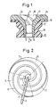
- the swirl body shown in FIG. 1 has a holding sleeve 15 which has a radially outwardly extending flange 16 and an essentially cylindrical section 17 with a circumferential, essentially V-shaped holding groove 18.
- a funnel sleeve 14 made of plastic or ceramic is inserted into the holding sleeve 15 in such a way that the funnel sleeve 14 lines the inner surface of the holding sleeve 15 and the upper end face of the flange 16.
- a holding sleeve 15 made of an elastic plastic can advantageously be used for this.
- a funnel-shaped or conical inlet opening 10 is provided, on the inner surface of which 13 ribs 11 are arranged.
- an extraction duct 12 which is connected to it in the sliver withdrawal direction R located outlet has a flared opening 19.
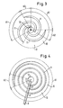
- Figure 2 shows the inlet opening 10 of a funnel sleeve 14 in plan view, so that the course of the three ribs 11 from the area of the discharge channel 12 to the outer edge of the inlet opening 10 can be followed.
- Each rib 11 extends over 360 and thus forms a complete revolution of a spiral. In this way it is ensured that the number of support points P of a fiber sliver 9 on the ribs 11 remains the same over the entire circumference of the inlet opening.
- three spirally circumferential ribs 11 are likewise arranged in the inlet opening 10 and are circumferentially offset from one another by 120 °.
- the individual ribs 11 extend in the circumferential direction of the inlet opening 10 only over 270 °, so that first and second sector sections A1, A2 are formed, in which the number of support points P for a fiber sliver 9 is two and three, respectively.
- FIG. 4 shows an inlet opening 10 with a single rib 11, which rotates somewhat over three spiral windings.
- a first and a second sector section A1 and A2 are also formed.
- the fiber sliver 9 lies on the support 11 at four support points p.
- the swirl bodies described are used in particular on pre-spinning machines or flyers, whereby they focus on the Wing attachments are arranged.
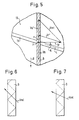
- the fiber sliver 9 is drawn off in the direction of the arrow R at a speed Va. This causes a displacement of the support point P along the fiber opposite to the direction of withdrawal, which is represented by the arrow Va '.
- the arrow Vr describes the movement of the rib 11 with respect to the fiber sliver 9 as a result of the rotational movement of the swirl body. If, for the sake of simplicity, we now consider the movement of the rib 11 with respect to a resting fiber sliver 9, the contact point P would be shifted against the draw-off direction R by the distance which is represented by the arrow v.
- the relative movement Vrel is therefore dependent on the take-off speed Va, the slope of the rib 11 at the point of contact P, that is to say the angle ⁇ between the longitudinal direction L of the rib 11 and the arrow Vr representing the rotational movement of the point P, and on the speed of the point P, which in turn depends on the distance of the point P from the culvert 12 and depends on the rotational speed of the swirl body.
- the relative displacement between the rib 11 and the fiber sliver 9, as shown in FIG. 6, is chosen approximately parallel to the pitch of the fibers in the yarn, the result is an essentially twist-blocking effect.
- the relative movement Vrel is chosen to be flatter than the pitch of the fibers in the fiber sliver 9, there is an essentially fiber-wrapping effect.
- a suitable choice of the variation of the slope of the rib from the inside to the outside, that is to say counter to the fiber sliver withdrawal direction R, can thus achieve a swirling or a fiber-wrapping effect in different radial regions of the inlet opening 10. In this way it is possible to produce very uniform fiber lunches with a smooth surface and even rotation distribution, the risk of rupture of the sliver being substantially reduced.
Landscapes
- Engineering & Computer Science (AREA)
- Mechanical Engineering (AREA)
- Textile Engineering (AREA)
- Spinning Or Twisting Of Yarns (AREA)
Abstract
Die Erfindung betrifft einen Drallkörper, insbesondere für Flyerflügel an Vorspinnmaschinen, mit einer trichterförmigen Einlauföffnung 10 für Faserlunten 9, auf deren Innenoberfläche 13 spiralförmig verlaufende Rippen 11 angeordnet sind. An die Einlauföffnung 10 schließt sich im Drallkörper ein Abzugskanal 12 an. Die Rippen 11 sind nach Anzahl und axialer Steigung so angeordnet, daß die einlaufende Faserlunte 9 ständig im Bereich der trichterförmigen Einlauföffnung 10 an zumindest zwei Auflagepunkten P auf Rippen 11 aufliegt und in dem Abzugskanal 12 benachbarten Bereich der Einlauföffnung 10 zumindest teilweise mit der Innenoberfläche 13 der Einlauföffnung 10 zwischen den Rippen 11 in Eingriff ist. <IMAGE>The invention relates to a swirl body, in particular for flyer wings on roving machines, with a funnel-shaped inlet opening 10 for fiber sliver 9, on the inner surface 13 of which spiral ribs 11 are arranged. At the inlet opening 10 in the swirl body is followed by an exhaust duct 12. The ribs 11 are arranged in number and axial pitch so that the incoming fiber sliver 9 is constantly in the area of the funnel-shaped inlet opening 10 on at least two support points P on ribs 11 and in the outlet channel 12 adjacent area of the inlet opening 10 at least partially with the inner surface 13 of the Inlet opening 10 is engaged between the ribs 11. <IMAGE>
Description
Die Erfindung betrifft einen Drallkörper, insbesondere für Flyerflügel an Vorspinnmaschinen, nach dem Oberbegriff des Patentanspruchs 1.The invention relates to a swirl body, in particular for flyer wings on roving machines, according to the preamble of patent claim 1.
Ein derartiger bekannter Drallkörper für Flyerflügel (DD 246 798 A1) weist einen Bund und einen rohrförmigen Ansatz auf. Durch den Drallkörper erstreckt sich dabei eine Bohrung, die sich im Bereich des Bundes so erweitert, daß sie eine trichterförmige Einlauföffnung bildet, auf deren Innenoberfläche in Axialrichtung spiralförmig verlaufende Stege angeordnet sind, die sich über reichlich ein Drittel der Länge der Bohrung erstrecken.Such a known swirl body for flyer wings (DD 246 798 A1) has a collar and a tubular extension. Through the swirl body extends a bore which widens in the region of the collar so that it forms a funnel-shaped inlet opening, on the inner surface of which spirally extending webs are arranged which extend over a third of the length of the bore.
Die spiralförmigen Stege sind dabei unter einem Steigungswinkel von mindestens 60 angeordnet. Die Breite der Stege, deren Anzahl sowie deren Höhe sind dabei so auf den Durchmesser des Abzugskanals abgestimmt, daß die Vorgarnlunte abrollen kann und nicht springt.The spiral webs are arranged at a pitch angle of at least 60. The width of the webs, their number and their height are matched to the diameter of the draw-off channel in such a way that the sliver can unroll and does not jump.
Der Drallkörper bietet also der Lunte quer zu ihrer Längsrichtung eine gewellte Oberfläche dar, während er in Abzugsrichtung der Lunte eine im wesentlichen glatte Oberfläche aufweist. Infolge der Abzugskraft für die Faserlunte wird diese im gesamten Bereich der Einlauföffnung an die Oberfläche der Einlauföffnung gedrückt, wodurch eine Abplattung der Lunte sowie erhebliche Reibungskräfte auftreten können, die die Luntenherstellung behindern und die zu Luntenbrüchen führen können.The swirl body thus provides the fuse with a corrugated surface transverse to its longitudinal direction, while it has an essentially smooth surface in the direction in which the fuse is withdrawn. As a result of the pulling force for the fiber sliver, the sliver is pressed against the surface of the inlet opening in the entire area of the inlet opening, as a result of which flattening of the sliver and considerable frictional forces can occur which hinder the sliver production and which can lead to sliver ruptures.
Bei einer bekannten Abzugsdüse für Vorspinn- und Spinneinrichtungen (DE 36 19 356 A1) ist es bekannt, in einen Grundkörper mit einer trichterförmiden Öffnung eine Drahtspirale einzusetzen. Diese Drahtspirale, die mit ihren in Abzugsrichtung der Faserlunte letzten Windungen bereits im Abzugskanal angeordnet ist, bietet für die einlaufende Faserlunte in deren Längsrichtung eine Vielzahl von Auflagepunkten. Dabei wird die Steigung der einzelnen Bindungen so gewählt, daß sie im axialen Abschnitt, also im Bereich des Abzugskanals, etwas größer ist als im Einlaufbereich. Jedoch darf die Steigung nicht zu groß gewählt werden, um Aufrauhungen des Garnes bzw. der Lunte zu vermeiden.In a known extraction nozzle for roving and spinning devices (DE 36 19 356 A1) it is known to insert a wire spiral into a base body with a funnel-shaped opening to use. This wire spiral, which with its last turns in the withdrawal direction of the fiber sliver is already arranged in the withdrawal channel, offers a large number of support points for the incoming fiber sliver in its longitudinal direction. The slope of the individual bonds is chosen so that it is somewhat larger in the axial section, that is to say in the area of the discharge channel, than in the inlet area. However, the pitch must not be too large to avoid roughening the yarn or the fuse.
Weiter sind Drallkörper bekannt (DE 30 23 546 A1) bei denen die trichterförmige Einlauföffnung gezahnt oder in ähnlicher Weise ausgebildet ist. Beispielsweise können ovale Kerben vorgesehen sein, deren Längsrichtung im wesentlichen mit der Lunteneinlaufrichtung zusammenfällt.Swirl bodies are also known (DE 30 23 546 A1) in which the funnel-shaped inlet opening is toothed or is designed in a similar manner. For example, oval notches can be provided, the longitudinal direction of which essentially coincides with the direction of the sliver inlet.
Die Aufgabe der vorliegenden Erfindung ist es, einen Drallkörper der eingangs genannten Art zu schaffen, mit dem eine Lunte mit gleichmäßiger und konstanter Drehungsverteilung herstellbar ist, die eine gleichmäßige und glatte Oberfläche aufweist.The object of the present invention is to provide a swirl body of the type mentioned at the outset with which a fuse with a uniform and constant distribution of rotation can be produced, which has a uniform and smooth surface.
Diese Aufgabe wird erfindungsgemäß durch die kennzeichnenden Merkmale des Patentanspruchs 1 gelöst.This object is achieved by the characterizing features of claim 1.
Durch die erfindungsgemäß vorgesehene Anordnung der Rippen, durch die die Lunte im Bereich der Einlauföffnung zum einem punktweise und zum anderen zumindest teilweise flächig abgestützt wird, läßt sich eine regelmäßigere und glatte Oberflächenstruktur der Lunte erzielen. Durch die wenigen ausgeprägten Auflagepunkte für die Lunte im Eingangsbereich der Einlauföffnung wird eine geringe Luntenlängskraft bei gleichzeitiger optimaler Drehungsfortpflanzung im Bereich des Drallkörpers erreicht. Hierdurch wird eine Produktionserhöhung bei gleichzeitig verbesserter Qualität der Lunten bzw. Vorgarne erzielt.The arrangement of the ribs provided according to the invention, by means of which the fuse in the area of the inlet opening is supported on the one hand at certain points and on the other at least partially over the surface, can achieve a more regular and smooth surface structure of the fuse. Due to the few pronounced support points for the fuse in the entrance area of the inlet opening, a low longitudinal force is achieved with simultaneous optimal propagation of rotation in the area of the swirl body. This results in an increase in production with improved quality of the sliver or roving.
Da erfindungsgemäß im Abzugskanal keine Rippen vorhanden sind, die dort eine stark aufrauhende Wirkung haben, was eine haarige Lunte erzeugt, wird die in der trichterförmigen Einlauföffnung geglättete Lunte nicht beeinträchtigt. Die Glättung der Lunte ergibt sich durch eine Streichbewegung, die die Rippen im Einlaufbereich relativ zur Lunte ausführen, wodurch abstehende Fasern angelegt und in der richtigen Steigung um die Lunte gelegt werden.Since, according to the invention, there are no ribs in the draw-off channel which have a strongly roughening effect there, which produces a hairy fuse, the fuse which is smoothed in the funnel-shaped inlet opening is not impaired. The fuse is smoothed by a brushing motion that the ribs in the infeed area perform relative to the fuse, whereby protruding fibers are applied and placed around the fuse at the correct incline.
Vorteilhafte Weiterbildungen der Erfindung sind in den Unteransprüchen 2 bis 6 beschrieben.Advantageous developments of the invention are described in subclaims 2 to 6.
Um den drallstauenden Effekt in Rücklaufkanalnähe mit dem Streicheffekt im konischen Teil der trichterförmigen Einlauföffnung zu kombinieren, ist die Ausführungsform der Erfindung nach Anspruch 7 vorgesehen.In order to combine the swirling effect in the vicinity of the return duct with the brushing effect in the conical part of the funnel-shaped inlet opening, the embodiment of the invention is provided according to claim 7.
Die Ausführungsformen nach Anspruch 8 oder 9 weisen dabei eine eher drallstauende Wirkung auf, währen die Ausführungsbeispiele nach Anspruch 10 bis 13 eher den Streicheffekt verstärken.The embodiments according to
Besonders vorteilhafte Materialien sind im Anspruch 14 beschrieben.Particularly advantageous materials are described in
Für die Herstellung und Montage besonders gut geeignete Ausführungsformen in der Erfindung sind in den Ansprüchen 15 bis 17 angegeben.Embodiments in the invention which are particularly suitable for the manufacture and assembly are specified in
Die Erfindung wird im folgenden beispielweise anhand der Zeichnung näher erläutert; in dieser zeigt:
- Figur 1
- einen Schnitt durch einen Drallkörper,
- Figur 2 bis 4
- Draufsichten auf die Einlauföffnung verschiedener Drallkörper mit unterschiedlicher Rippenanordnung,
- Figur 5
- eine schematische teilweise Draufsicht auf eine über eine Rippe laufende Faserlunte und
- Figur 6 und 7
- jeweils einen Ausschnitt einer Faserlunte, wobei die Relativbewegung zwischen Faserlunte und Rippe in Bezug auf die Drehung der Lunte dargestellt ist.
- Figure 1
- a section through a swirl body,
- Figure 2 to 4
- Top views of the inlet opening of different swirl bodies with different rib arrangement,
- Figure 5
- is a schematic partial plan view of a fiber sliver running over a rib and
- Figures 6 and 7
- each a section of a fiber sliver, the relative movement between the fiber sliver and the rib being shown in relation to the rotation of the sliver.
In den verschiedenen Figuren der Zeichnung sind einander entsprechende Teile mit gleichen Bezugszeichen versehen.Corresponding parts in the various figures of the drawing are provided with the same reference symbols.
Der in Figur 1 dargestellte Drallkörper weist eine Haltehülse 15 auf, die einen sich radial nach außen erstreckenden Flansch 16 und einen im wesentlichen zylindrischen Abschnitt 17 mit einer umfangsmäßig umlaufenden, im wesentlichen V-förmigen Haltenut 18 besitzt. In die Haltehülse 15 ist eine Trichterhülse 14 aus Kunststoff oder Keramik so eingesetzt, daß die Trichterhülse 14 die Innenoberfläche der Haltehülse 15 und die obere Stirnfläche des Flansches 16 auskleidet.The swirl body shown in FIG. 1 has a
Wird ein derartiger Drallkörper z.B. auf einem Flyerflügel verwendet, so lassen sich bei geeigneter Anbringung die Vorteile einer flexiblen befestigung nutzen. Hierfür kann in vorteilhafterweise eine Haltehülse 15 aus einem elastischen Kunststoff verwendet werden.If such a swirl body is e.g. used on a flyer wing, the advantages of flexible attachment can be used with a suitable attachment. A
In der Trichterhülse 14 ist eine trichterförmige oder konische Einlauföffnung 10 vorgesehen, auf deren Innenoberfläche 13 Rippen 11 angeordnet sind. An die Einlauföffnung 10 schließt sich ein Abzugskanal 12 an, der an seinem in Luntenabzugsrichtung R gelegenen Auslaß eine konisch erweiterte Abzugsöffnung 19 aufweist.In the
Figur 2 zeigt die Einlauföffnung 10 einer Trichterhülse 14 in Draufsicht, so daß man den Verlauf der drei Rippen 11 vom Bereich des Abzugskanals 12 bis zum äußeren Rand der Einlauföffnung 10 verfolgen kann. Dabei erstreckt sich jede Rippe 11 über 360 und bildet somit einen vollständigen Umlauf einer Spirale. Auf diese Weise wird sichergestellt, daß die Anzahl von Auflagepunkten P einer Faserlunte 9 auf den Rippen 11 über den gesamten Umfang der Einlauföffnung gleich bleibt.Figure 2 shows the inlet opening 10 of a
Bei dem in Figur 3 dargestellten Drallkörper sind in der Einlauföffnung 10 ebenfalls drei spiralförmig umlaufende Rippen 11 angeordnet, die zueinander umfangsmäßig jeweils um 120° versetzt sind. Die einzelnen Rippen 11 erstrecken sich im Umfangsrichtung der Einlauföffnung 10 jedoch nur über 270°, so daß erste und zweite Sektorabschnitte A1, A2 gebildet werden, in denen die Anzahl der Auflagepunkte P für eine Faserlunte 9 zwei bzw. drei beträgt.In the swirl body shown in FIG. 3, three spirally
Figur 4 zeigt eine Einlauföffnung 10 mit einer einzigen Rippe 11, die insgesamt etwas über drei Spiralwindungen umläuft. Auf diese Weise wird ebenfalls ein erster und ein zweiter Sektorabschnitt A1 bzw. A2 gebildet. Im ersten Sektorabschnitt A1 liegt die Faserlunte 9 dabei an vier Auflagepunkten p auf der Rippe 11 auf.FIG. 4 shows an inlet opening 10 with a
Infolge der variablen Steigung der Rippen ändert sich von Auflagepunkt P zu Auflagepunkt P jeweils der Winkel zwischen der Faserlunte 9 und der Tangente an die Rippe 11 im jeweiligen Auflagepunkt P.As a result of the variable slope of the ribs, the angle between the
Die beschriebenen Drallkörper werden insbesondere an Vorspinnmaschinen bzw. Flyern eingesetzt, wobei sie auf den Flügelaufsätzen angeordnet sind. Dabei wird die Faserlunte 9, die von einem Spinndreieck am entsprechenden Streckwerk eines Flyers kommt, durch die Einlauföffnung 10 und den Abzugskanal 12 hindurch zum Flyerflügel geführt, um schließlich auf einer entsprechenden Vorgarnspule aufgewickelt zu werden.The swirl bodies described are used in particular on pre-spinning machines or flyers, whereby they focus on the Wing attachments are arranged. The
Da sich der Drallkörper zusammen mit dem Flyerflügel dreht, tritt zwischen der Faserlunte 9 und der jeweiligen Rippe 11 eine Relativbewegung auf, die anhand von Figur 5 beschrieben wird.Since the swirl body rotates together with the flyer wing, a relative movement occurs between the
Wie in Figur 5 dargestellt, wird die Faserlunte 9 in Richtung des Pfeiles R mit einer Geschwindigkeit Va abgezogen. Hierdurch wird eine Verschiebung des Auflagepunktes P entlang der Faser entgegengesetzt zur Abzugsrichtung bewirkt, die durch den Pfeil Va' dargestellt ist. Der Pfeil Vr beschreibt die Bewegung der Rippe 11 gegenüber der Faserlunte 9 in Folge der Rotationsbewegung des Drallkörpers. Betrachtet man nun der Einfachheit halber die Bewegung der Rippe 11 gegenüber einer ruhenden Faserlunte 9 so würde der Auflagepunkt P entgegen der Abzugsrichtung R um die Strecke verschoben werden, die durch den Pfeil v dargestellt ist.As shown in FIG. 5, the
Bei ruhender Faserlunte 9 würde also der Auflagepunkt P entsprechend dem Pfeil Vr' verschoben werden. Hieraus ergibt sich durch normale Vektoraddition die Richtung der Relativbewegung Vrel der Faserlunte 9 gegenüber der Rippe 11 im Auflagepunkt P.With the
Die Relativbewegung Vrel ist also abhängig von der Abzugsgeschwindigkeit Va, der Steigung der Rippe 11 im Auflagepunkt P, also dem Winkel α zwischen der Längsrichtung L der Rippe 11 und dem die Rotationsbewegung des Punktes P darstellenden Pfeiles Vr, und von der Geschwindigkeit des Punktes P, die wiederum vom Abstand des Punktes P vom Abzugskanal 12 sowie von der Drehgeschwindigkeit des Drallkörpers abhängt.The relative movement Vrel is therefore dependent on the take-off speed Va, the slope of the
Wird nun die Relativverschiebung zwischen Rippe 11 und Faserlunte 9 wie in Figur 6 dargestellt etwa parallel zur Steigung der Fasern im Garn gewählt, so ergibt sich eine im wesentlichen drallstauende Wirkung. Wird andererseits, wie anhand von Figur 7 gezeigt, die Relativbewegung Vrel flacher als die Steigung der Fasern in der Faserlunte 9 gewählt, so ergibt sich eine im wesentlichen faserumwindende Wirkung. Durch eine geeignete Wahl der Variation der Steigung der Rippe von innen nach außen, also entgegen der Faserluntenabzugsrichtung R kann somit in unterschiedlichen Radialbereichen der Einlauföffnung 10 mehr eine drallstauende oder eine faserumwindende Wirkung erzielt werden. Auf diese Weise lassen sich sehr gleichmäßige Faserlunten mit glatter Oberfläche und gleichmäßiger Drehungsverteilung erzeugen, wobei die Gefahr von Luntenbrüchen wesentlich verringert ist.If the relative displacement between the
Claims (17)
dadurch gekennzeichnet,
daß die Rippen (11) nach Anzahl und axialer Steigung so angeordnet sind, daß die einlaufende Faserlunte (9) ständig im Bereich der trichterförmigen Einlauföffnung (10) an zumindest zwei Auflagepunkten (P) auf den Rippen (11) aufliegt und in dem Einlaufkanal (12) benachbarten Bereich der Einlauföffnung (10) zumindest teilweise mit der Innenoberfläche (13) der Einlauföffnung zwischen den Rippen (11) in Eingriff ist.Swirl bodies, in particular for flyer wings on roving machines, with a funnel-shaped inlet opening for fiber lunches, on the inner surface of which spirally extending ribs are arranged, and with an adjoining extraction duct,
characterized,
that the ribs (11) are arranged in number and axial pitch so that the incoming fiber sliver (9) is constantly in contact with the ribs (11) in the area of the funnel-shaped inlet opening (10) at at least two support points (P) and in the inlet channel ( 12) adjacent area of the inlet opening (10) is at least partially engaged with the inner surface (13) of the inlet opening between the ribs (11).
dadurch gekennzeichnet,
daß wenigstens drei Auflagepunkte (P) für die einlaufende Faserlunte (9) vorgesehen sind.Swirl body according to claim 1,
characterized,
that at least three support points (P) are provided for the incoming fiber sliver (9).
dadurch gekennzeichnet,
daß die Anzahl der Auflagepunkte (P) in Umfangsrichtung der Einlauföffnung (10) abschnittsweise wechselt.Swirl body according to claim 1 or 2,
characterized by
that the number of support points (P) changes in sections in the circumferential direction of the inlet opening (10).
dadurch gekennzeichnet,
daß die Anzahl der für die einlaufende Faserlunte (9) vorgesehenen Auflagepunkte (P) in ersten umfangsmäßig verteilt angeordneten Sektorabschnitten (A1) der Einlauföffnung (10) um 1 geringer ist, als in jeweils umfangsmäßig benachbart dazu angeordneten zweiten Sektorabschnitten (A2).Swirl body according to claim 3,
characterized,
that the number of support points (P) provided for the incoming fiber sliver (9) in first circumferentially distributed sector sections (A1) of the inlet opening (10) is 1 less than in circumferentially adjacent second sector sections (A2).
dadurch gekennzeichnet,
daß für die einlaufende Faserlunte (9) in den ersten Sektorabschnitten (A1) drei und in den zweiten Sektorabschnitten (A2) vier Auflagepunkte (P) vorgesehen sind.Swirl body according to claim 4,
characterized,
that three contact points (P) are provided for the incoming fiber sliver (9) in the first sector sections (A1) and four in the second sector sections (A2).
dadurch gekennzeichnet,
daß die Anzahl der für die einlaufende Faserlunte (9) vorgesehenen Auflagepunkte (P) in Umfangsrichtung der Einlauföffnung (10) gleich bleibt.Swirl body according to claim 1 or 2,
characterized,
that the number of support points (P) provided for the incoming fiber sliver (9) in the circumferential direction of the inlet opening (10) remains the same.
dadurch gekennzeichnet,
daß die spiralförmig verlaufenden Rippen (11) eine variable Steigung aufweisen.Swirl body according to one of the preceding claims,
characterized,
that the spiral ribs (11) have a variable slope.
dadurch gekennzeichnet,
daß eine einzelne spiralförmig verlaufenden Rippe (9) vorgesehen ist, deren Steigung von innen nach außen, also entgegen der Luntenabzugsrichtung (R), von etwa 60° auf etwa 10° abnimmt.Swirl body according to claim 7,
characterized,
that a single spiral rib (9) is provided, the slope of which decreases from the inside to the outside, that is to say counter to the sliver withdrawal direction (R), from approximately 60 ° to approximately 10 °.
dadurch gekennzeichnet,
daß die von der einen Rippe (11) gebildete Spirale wenigstens drei Windungen aufweist.Swirl body according to claim 8.
characterized,
that the spiral formed by the one rib (11) has at least three turns.
dadurch gekennzeichnet,
daß drei spiralförmig verlaufende Rippen (11) vorgesehen sind, deren Steigung jeweils von innen nach außen, also entgegen der Luntenabzugsrichtung (R), von etwa 30° auf etwa 10° abnimmt.Swirl body according to claim 7.
characterized,
that three spiral ribs (11) are provided, the incline of which decreases from the inside to the outside, that is to say counter to the direction of the roving (R), from approximately 30 ° to approximately 10 °.
dadurch gekennzeichnet,
daß die Rippen (11) nach Art einer dreigängigen Spirale in Umfangsrichtung der Einlauföffnung (10) gleichmäßig verteilt angeordnet sind.Swirl body according to claim 10,
characterized,
that the ribs (11) are arranged evenly distributed in the circumferential direction of the inlet opening (10) in the manner of a three-start spiral.
dadurch gekennzeichnet,
daß sich jede Rippe (11) in Umfangsrichtung der Einlauföffnung (10) über etwa 360° erstreckt.Swirl body according to claim 10 or 11,
characterized,
that each rib (11) extends in the circumferential direction of the inlet opening (10) over approximately 360 °.
dadurch gekennzeichnet,
daß sich jede Rippe in Umfangsrichtung der Einlauföffnung (10) über zumindest 270° erstreckt.Swirl body according to claim 10 or 11,
characterized,
that each rib extends in the circumferential direction of the inlet opening (10) over at least 270 °.
dadurch gekennzeichnet,
daß er aus Keramik , Kunststoff oder Metall hergestellt ist.Swirl body according to one of the preceding claims,
characterized,
that it is made of ceramic, plastic or metal.
dadurch gekennzeichnet,
daß die Einlauföffnung (10) und der Einlaufkanal (12) an der Innenseite einer Trichterhülse (14) ausgebildet sind, die in einer Haltehülse (15) eingesetzt ist.Swirl body according to one of claims 1 to 13,
characterized,
that the inlet opening (10) and the inlet channel (12) are formed on the inside of a funnel sleeve (14) which is inserted in a holding sleeve (15).
dadurch gekennzeichnet,
daß die Trichterhülse (14) aus Metall, Keramik oder Kunststoff besteht.Swirl body according to claim 15,
characterized,
that the funnel sleeve (14) consists of metal, ceramic or plastic.
dadurch gekennzeichnet,
daß die Haltehülse (15) aus Metall oder Kunststoff besteht.Swirl body according to claim 15 or 16,
characterized,
that the holding sleeve (15) consists of metal or plastic.
Applications Claiming Priority (2)
| Application Number | Priority Date | Filing Date | Title |
|---|---|---|---|
| DE4010140 | 1990-03-29 | ||
| DE19904010140 DE4010140A1 (en) | 1990-03-29 | 1990-03-29 | SPIRAL BODY, ESPECIALLY FOR FLYER WINGS ON RASPING MACHINES |
Publications (2)
| Publication Number | Publication Date |
|---|---|
| EP0449068A2 true EP0449068A2 (en) | 1991-10-02 |
| EP0449068A3 EP0449068A3 (en) | 1991-12-04 |
Family
ID=6403347
Family Applications (1)
| Application Number | Title | Priority Date | Filing Date |
|---|---|---|---|
| EP19910104104 Withdrawn EP0449068A3 (en) | 1990-03-29 | 1991-03-16 | Spinning funnel, particularly for flyer on a roving frame |
Country Status (2)
| Country | Link |
|---|---|
| EP (1) | EP0449068A3 (en) |
| DE (1) | DE4010140A1 (en) |
Cited By (2)
| Publication number | Priority date | Publication date | Assignee | Title |
|---|---|---|---|---|
| WO1995018059A1 (en) * | 1993-12-29 | 1995-07-06 | Nuova Roj Electrotex S.R.L. | Device to control the yarn at the outlet of yarn feeders for looms |
| CN103436999A (en) * | 2013-07-23 | 2013-12-11 | 经纬纺织机械股份有限公司 | Cotton passing flaring of combing machine |
Families Citing this family (5)
| Publication number | Priority date | Publication date | Assignee | Title |
|---|---|---|---|---|
| DE10001468A1 (en) * | 2000-01-15 | 2001-07-19 | Rieter Ingolstadt Spinnerei | Yarn take-off jet at an open-end spinner has structured ring projections at the yarn contact surface to give a progression of the yarn twist to the yarn/fiber bonding point for spinning softer yarns without abrasion |
| DE10222635A1 (en) * | 2002-05-17 | 2003-12-18 | Ilias Efthimiou | off nozzle |
| DE10334758B4 (en) * | 2002-08-19 | 2013-12-05 | Rieter Ingolstadt Gmbh | Turntable of a spinning machine and spinning machine |
| DE10244497A1 (en) * | 2002-09-25 | 2004-04-08 | Saurer Gmbh & Co. Kg | Jet entry into the yarn take-off channel, at an open-end spinner, has a spiral structure with at least two sectors where the spiral pitches differ to prevent an excessive yarn twist |
| DE102004036953B4 (en) * | 2004-07-21 | 2012-11-08 | Wilhelm Stahlecker Gmbh | Garnabzugsdüse for an open-end rotor spinning device |
Family Cites Families (7)
| Publication number | Priority date | Publication date | Assignee | Title |
|---|---|---|---|---|
| DE2405674C2 (en) * | 1974-02-06 | 1982-04-29 | Kostromskoe Special'noe Konstruktorskoe Bjuro Tekstil'nych Mašin, Kostroma | Open-end spinning machine |
| US4122653A (en) * | 1977-08-08 | 1978-10-31 | Argereu W | Grommet for roving machine |
| DE3023546A1 (en) * | 1980-06-24 | 1982-01-21 | C. Eugen Maier Metallverarbeitung Gmbh, 7012 Fellbach | SPIDER OR FLYER WING |
| DD255054A3 (en) * | 1985-08-29 | 1988-03-23 | Karl Marx Stadt Tech Hochschul | EXTRACTION DUESE FOR PRE-SPILL AND SPINNING DEVICES |
| EP0220546A1 (en) * | 1985-10-15 | 1987-05-06 | Maschinenfabrik Rieter Ag | Spinning device for open-end spinning |
| DD246798A1 (en) * | 1986-03-24 | 1987-06-17 | Textima Veb K | DRALLKOERPER FOR FLYER FLUEGEL ON PRE-SPILL MACHINES |
| DE3707526A1 (en) * | 1987-03-09 | 1988-09-29 | Vnii Legkogo Textil Masch | UNIT FOR RINGLESS SPINNING |
-
1990
- 1990-03-29 DE DE19904010140 patent/DE4010140A1/en not_active Withdrawn
-
1991
- 1991-03-16 EP EP19910104104 patent/EP0449068A3/en not_active Withdrawn
Cited By (5)
| Publication number | Priority date | Publication date | Assignee | Title |
|---|---|---|---|---|
| WO1995018059A1 (en) * | 1993-12-29 | 1995-07-06 | Nuova Roj Electrotex S.R.L. | Device to control the yarn at the outlet of yarn feeders for looms |
| US5715871A (en) * | 1993-12-29 | 1998-02-10 | Nuova Roj Electrotex S.R.L. | Frustoconical device with internal ribs for loom yarn feeders |
| CN1046481C (en) * | 1993-12-29 | 1999-11-17 | 诺瓦·罗伊电子公司 | Device to control yarn at the outlet of yarn feeders for looms |
| CN103436999A (en) * | 2013-07-23 | 2013-12-11 | 经纬纺织机械股份有限公司 | Cotton passing flaring of combing machine |
| CN103436999B (en) * | 2013-07-23 | 2015-12-02 | 经纬纺织机械股份有限公司 | Cotton oviduct crossed by a kind of combing machine |
Also Published As
| Publication number | Publication date |
|---|---|
| EP0449068A3 (en) | 1991-12-04 |
| DE4010140A1 (en) | 1991-10-02 |
Similar Documents
| Publication | Publication Date | Title |
|---|---|---|
| DE2660983C2 (en) | Process for pneumatic twist spinning | |
| EP2895647B1 (en) | Spinning station of a roving machine | |
| EP0220546A1 (en) | Spinning device for open-end spinning | |
| DE3639136A1 (en) | FLANGE MADE OF FIBER REINFORCED THERMO-HARDENING RESIN AND METHOD FOR THE PRODUCTION THEREOF | |
| CH660498A5 (en) | METHOD AND DEVICE FOR INCREASING THE HAIRNESS AND VOLUMINOSITY OF A THREAD. | |
| DE3301652A1 (en) | FALSE WIRE AIR NOZZLE | |
| DE1806054A1 (en) | Method and device for spinning a sliver | |
| DE3207136A1 (en) | METHOD AND DEVICE FOR PRODUCING A THREAD | |
| EP2454403B1 (en) | Air-jet spinning apparatus | |
| DE102008006379A1 (en) | Air-jet spinning device for use in production of yarn, has cladding gap downstream to plane, in which air flow initially withdrawing from nozzles impinges housing part surface, where gap width suddenly increases and is in specific range | |
| EP1431432B1 (en) | Device for producing a spun yarn | |
| EP1415027B1 (en) | Device for producing a spun yarn | |
| EP3371353B1 (en) | Thread draw-off nozzle having notches extending radially to the nozzle bore | |
| DE4010140A1 (en) | SPIRAL BODY, ESPECIALLY FOR FLYER WINGS ON RASPING MACHINES | |
| DE3714212A1 (en) | Apparatus for pneumatic false-twist spinning having a drafting unit | |
| EP3052683B1 (en) | Spinning station equipped with a fiber guiding element | |
| EP1284312A2 (en) | Apparatus for producing spun yarn | |
| EP3464691B1 (en) | Yarn forming element for a pre-spinning machine and pre-spinning machine equipped therewith | |
| EP2578730B1 (en) | Thread creation element for a spinning position of an air jet spinning machine with a twist stop element | |
| EP3680373B1 (en) | Fibre guide element for a spinning nozzle and spinning nozzle provided with same | |
| DE3325699A1 (en) | METHOD AND DEVICE FOR PRODUCING A FIBER BUNCH YARN | |
| DE4326205C1 (en) | Round comb | |
| DD255054A3 (en) | EXTRACTION DUESE FOR PRE-SPILL AND SPINNING DEVICES | |
| EP0606434B1 (en) | Device for spinning a sliver | |
| AT398085B (en) | Apparatus for the production of a yarn |
Legal Events
| Date | Code | Title | Description |
|---|---|---|---|
| PUAI | Public reference made under article 153(3) epc to a published international application that has entered the european phase |
Free format text: ORIGINAL CODE: 0009012 |
|
| AK | Designated contracting states |
Kind code of ref document: A2 Designated state(s): CH ES FR GB IT LI |
|
| PUAL | Search report despatched |
Free format text: ORIGINAL CODE: 0009013 |
|
| AK | Designated contracting states |
Kind code of ref document: A3 Designated state(s): CH ES FR GB IT LI |
|
| 17P | Request for examination filed |
Effective date: 19920403 |
|
| STAA | Information on the status of an ep patent application or granted ep patent |
Free format text: STATUS: THE APPLICATION IS DEEMED TO BE WITHDRAWN |
|
| 18D | Application deemed to be withdrawn |
Effective date: 19931001 |