EP0449068A2 - Entonnoir rotatif, particulièrement pour une ailette sur une machine à broches - Google Patents
Entonnoir rotatif, particulièrement pour une ailette sur une machine à broches Download PDFInfo
- Publication number
- EP0449068A2 EP0449068A2 EP91104104A EP91104104A EP0449068A2 EP 0449068 A2 EP0449068 A2 EP 0449068A2 EP 91104104 A EP91104104 A EP 91104104A EP 91104104 A EP91104104 A EP 91104104A EP 0449068 A2 EP0449068 A2 EP 0449068A2
- Authority
- EP
- European Patent Office
- Prior art keywords
- body according
- inlet opening
- swirl body
- ribs
- swirl
- Prior art date
- Legal status (The legal status is an assumption and is not a legal conclusion. Google has not performed a legal analysis and makes no representation as to the accuracy of the status listed.)
- Withdrawn
Links
Images
Classifications
-
- D—TEXTILES; PAPER
- D01—NATURAL OR MAN-MADE THREADS OR FIBRES; SPINNING
- D01H—SPINNING OR TWISTING
- D01H7/00—Spinning or twisting arrangements
- D01H7/02—Spinning or twisting arrangements for imparting permanent twist
- D01H7/24—Flyer or like arrangements
- D01H7/46—Devices attached to, or integral with, flyers for temporarily increasing twist in material passing to them
-
- D—TEXTILES; PAPER
- D01—NATURAL OR MAN-MADE THREADS OR FIBRES; SPINNING
- D01H—SPINNING OR TWISTING
- D01H13/00—Other common constructional features, details or accessories
- D01H13/04—Guides for slivers, rovings, or yarns; Smoothing dies
Definitions
- the invention relates to a swirl body, in particular for flyer wings on roving machines, according to the preamble of patent claim 1.
- Such a known swirl body for flyer wings (DD 246 798 A1) has a collar and a tubular extension. Through the swirl body extends a bore which widens in the region of the collar so that it forms a funnel-shaped inlet opening, on the inner surface of which spirally extending webs are arranged which extend over a third of the length of the bore.
- the spiral webs are arranged at a pitch angle of at least 60.
- the width of the webs, their number and their height are matched to the diameter of the draw-off channel in such a way that the sliver can unroll and does not jump.
- the swirl body thus provides the fuse with a corrugated surface transverse to its longitudinal direction, while it has an essentially smooth surface in the direction in which the fuse is withdrawn.
- the sliver is pressed against the surface of the inlet opening in the entire area of the inlet opening, as a result of which flattening of the sliver and considerable frictional forces can occur which hinder the sliver production and which can lead to sliver ruptures.
- Swirl bodies are also known (DE 30 23 546 A1) in which the funnel-shaped inlet opening is toothed or is designed in a similar manner.
- oval notches can be provided, the longitudinal direction of which essentially coincides with the direction of the sliver inlet.
- the object of the present invention is to provide a swirl body of the type mentioned at the outset with which a fuse with a uniform and constant distribution of rotation can be produced, which has a uniform and smooth surface.
- the arrangement of the ribs provided according to the invention by means of which the fuse in the area of the inlet opening is supported on the one hand at certain points and on the other at least partially over the surface, can achieve a more regular and smooth surface structure of the fuse. Due to the few pronounced support points for the fuse in the entrance area of the inlet opening, a low longitudinal force is achieved with simultaneous optimal propagation of rotation in the area of the swirl body. This results in an increase in production with improved quality of the sliver or roving.
- the fuse which is smoothed in the funnel-shaped inlet opening is not impaired.
- the fuse is smoothed by a brushing motion that the ribs in the infeed area perform relative to the fuse, whereby protruding fibers are applied and placed around the fuse at the correct incline.
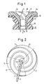
- the swirl body shown in FIG. 1 has a holding sleeve 15 which has a radially outwardly extending flange 16 and an essentially cylindrical section 17 with a circumferential, essentially V-shaped holding groove 18.
- a funnel sleeve 14 made of plastic or ceramic is inserted into the holding sleeve 15 in such a way that the funnel sleeve 14 lines the inner surface of the holding sleeve 15 and the upper end face of the flange 16.
- a holding sleeve 15 made of an elastic plastic can advantageously be used for this.
- a funnel-shaped or conical inlet opening 10 is provided, on the inner surface of which 13 ribs 11 are arranged.
- an extraction duct 12 which is connected to it in the sliver withdrawal direction R located outlet has a flared opening 19.
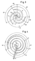
- Figure 2 shows the inlet opening 10 of a funnel sleeve 14 in plan view, so that the course of the three ribs 11 from the area of the discharge channel 12 to the outer edge of the inlet opening 10 can be followed.
- Each rib 11 extends over 360 and thus forms a complete revolution of a spiral. In this way it is ensured that the number of support points P of a fiber sliver 9 on the ribs 11 remains the same over the entire circumference of the inlet opening.
- three spirally circumferential ribs 11 are likewise arranged in the inlet opening 10 and are circumferentially offset from one another by 120 °.
- the individual ribs 11 extend in the circumferential direction of the inlet opening 10 only over 270 °, so that first and second sector sections A1, A2 are formed, in which the number of support points P for a fiber sliver 9 is two and three, respectively.
- FIG. 4 shows an inlet opening 10 with a single rib 11, which rotates somewhat over three spiral windings.
- a first and a second sector section A1 and A2 are also formed.
- the fiber sliver 9 lies on the support 11 at four support points p.
- the swirl bodies described are used in particular on pre-spinning machines or flyers, whereby they focus on the Wing attachments are arranged.
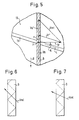
- the fiber sliver 9 is drawn off in the direction of the arrow R at a speed Va. This causes a displacement of the support point P along the fiber opposite to the direction of withdrawal, which is represented by the arrow Va '.
- the arrow Vr describes the movement of the rib 11 with respect to the fiber sliver 9 as a result of the rotational movement of the swirl body. If, for the sake of simplicity, we now consider the movement of the rib 11 with respect to a resting fiber sliver 9, the contact point P would be shifted against the draw-off direction R by the distance which is represented by the arrow v.
- the relative movement Vrel is therefore dependent on the take-off speed Va, the slope of the rib 11 at the point of contact P, that is to say the angle ⁇ between the longitudinal direction L of the rib 11 and the arrow Vr representing the rotational movement of the point P, and on the speed of the point P, which in turn depends on the distance of the point P from the culvert 12 and depends on the rotational speed of the swirl body.
- the relative displacement between the rib 11 and the fiber sliver 9, as shown in FIG. 6, is chosen approximately parallel to the pitch of the fibers in the yarn, the result is an essentially twist-blocking effect.
- the relative movement Vrel is chosen to be flatter than the pitch of the fibers in the fiber sliver 9, there is an essentially fiber-wrapping effect.
- a suitable choice of the variation of the slope of the rib from the inside to the outside, that is to say counter to the fiber sliver withdrawal direction R, can thus achieve a swirling or a fiber-wrapping effect in different radial regions of the inlet opening 10. In this way it is possible to produce very uniform fiber lunches with a smooth surface and even rotation distribution, the risk of rupture of the sliver being substantially reduced.
Landscapes
- Engineering & Computer Science (AREA)
- Mechanical Engineering (AREA)
- Textile Engineering (AREA)
- Spinning Or Twisting Of Yarns (AREA)
Applications Claiming Priority (2)
| Application Number | Priority Date | Filing Date | Title |
|---|---|---|---|
| DE4010140 | 1990-03-29 | ||
| DE19904010140 DE4010140A1 (de) | 1990-03-29 | 1990-03-29 | Drallkoerper, insbesondere fuer flyerfluegel an vorspinnmaschinen |
Publications (2)
| Publication Number | Publication Date |
|---|---|
| EP0449068A2 true EP0449068A2 (fr) | 1991-10-02 |
| EP0449068A3 EP0449068A3 (en) | 1991-12-04 |
Family
ID=6403347
Family Applications (1)
| Application Number | Title | Priority Date | Filing Date |
|---|---|---|---|
| EP19910104104 Withdrawn EP0449068A3 (en) | 1990-03-29 | 1991-03-16 | Spinning funnel, particularly for flyer on a roving frame |
Country Status (2)
| Country | Link |
|---|---|
| EP (1) | EP0449068A3 (fr) |
| DE (1) | DE4010140A1 (fr) |
Cited By (2)
| Publication number | Priority date | Publication date | Assignee | Title |
|---|---|---|---|---|
| WO1995018059A1 (fr) * | 1993-12-29 | 1995-07-06 | Nuova Roj Electrotex S.R.L. | Dispositif de regulation du fil sortant des predelivreurs de metiers a tisser |
| CN103436999A (zh) * | 2013-07-23 | 2013-12-11 | 经纬纺织机械股份有限公司 | 一种精梳机过棉喇叭管 |
Families Citing this family (5)
| Publication number | Priority date | Publication date | Assignee | Title |
|---|---|---|---|---|
| DE10001468A1 (de) * | 2000-01-15 | 2001-07-19 | Rieter Ingolstadt Spinnerei | Fadenabzugsdüse für eine Offenend-Spinnmaschine |
| DE10222635A1 (de) * | 2002-05-17 | 2003-12-18 | Ilias Efthimiou | Fadenabzugsdüse |
| DE10334758B4 (de) * | 2002-08-19 | 2013-12-05 | Rieter Ingolstadt Gmbh | Drehteller einer Spinnereimaschine sowie Spinnereimaschine |
| DE10244497A1 (de) * | 2002-09-25 | 2004-04-08 | Saurer Gmbh & Co. Kg | Offenend-Spinnvorrichtung |
| DE102004036953B4 (de) * | 2004-07-21 | 2012-11-08 | Wilhelm Stahlecker Gmbh | Garnabzugsdüse für eine Offenend-Rotorspinnvorrichtung |
Family Cites Families (7)
| Publication number | Priority date | Publication date | Assignee | Title |
|---|---|---|---|---|
| DE2405674C2 (de) * | 1974-02-06 | 1982-04-29 | Kostromskoe Special'noe Konstruktorskoe Bjuro Tekstil'nych Mašin, Kostroma | Offenendspinnmaschine |
| US4122653A (en) * | 1977-08-08 | 1978-10-31 | Argereu W | Grommet for roving machine |
| DE3023546A1 (de) * | 1980-06-24 | 1982-01-21 | C. Eugen Maier Metallverarbeitung Gmbh, 7012 Fellbach | Spinn- oder flyerfluegel |
| DD255054A3 (de) * | 1985-08-29 | 1988-03-23 | Karl Marx Stadt Tech Hochschul | Abzugsduese fuer vorspinn- und spinneinrichtungen |
| EP0220546A1 (fr) * | 1985-10-15 | 1987-05-06 | Maschinenfabrik Rieter Ag | Dispositif de filature à bout libre |
| DD246798A1 (de) * | 1986-03-24 | 1987-06-17 | Textima Veb K | Drallkoerper fuer flyerfluegel an vorspinnmaschinen |
| DE3707526A1 (de) * | 1987-03-09 | 1988-09-29 | Vnii Legkogo Textil Masch | Einrichtung zum ringlosen spinnen |
-
1990
- 1990-03-29 DE DE19904010140 patent/DE4010140A1/de not_active Withdrawn
-
1991
- 1991-03-16 EP EP19910104104 patent/EP0449068A3/de not_active Withdrawn
Cited By (5)
| Publication number | Priority date | Publication date | Assignee | Title |
|---|---|---|---|---|
| WO1995018059A1 (fr) * | 1993-12-29 | 1995-07-06 | Nuova Roj Electrotex S.R.L. | Dispositif de regulation du fil sortant des predelivreurs de metiers a tisser |
| US5715871A (en) * | 1993-12-29 | 1998-02-10 | Nuova Roj Electrotex S.R.L. | Frustoconical device with internal ribs for loom yarn feeders |
| CN1046481C (zh) * | 1993-12-29 | 1999-11-17 | 诺瓦·罗伊电子公司 | 在织机供线器出口控制纱线的装置 |
| CN103436999A (zh) * | 2013-07-23 | 2013-12-11 | 经纬纺织机械股份有限公司 | 一种精梳机过棉喇叭管 |
| CN103436999B (zh) * | 2013-07-23 | 2015-12-02 | 经纬纺织机械股份有限公司 | 一种精梳机过棉喇叭管 |
Also Published As
| Publication number | Publication date |
|---|---|
| EP0449068A3 (en) | 1991-12-04 |
| DE4010140A1 (de) | 1991-10-02 |
Similar Documents
| Publication | Publication Date | Title |
|---|---|---|
| DE2660983C2 (de) | Verfahren zum pneumatischen Drallspinnen | |
| EP2895647B1 (fr) | Poste de filage d'un banc à broches | |
| EP0220546A1 (fr) | Dispositif de filature à bout libre | |
| DE3639136A1 (de) | Flansch aus faserverstaerktem thermohaertendem kunstharz und verfahren zu seiner herstellung | |
| CH660498A5 (de) | Verfahren und vorrichtung zum erhoehen der haarigkeit und voluminositaet eines fadens. | |
| DE3301652A1 (de) | Falschdraht-luftduese | |
| DE1806054A1 (de) | Verfahren und Vorrichtung zum Verspinnen eines Faserbandes | |
| DE3207136A1 (de) | Verfahren und vorrichtung zum herstellen eines fadens | |
| EP2454403B1 (fr) | Machine à filer à jet d'air | |
| DE102008006379A1 (de) | Luftspinnvorrichtung | |
| EP1431432B1 (fr) | Dispositif pour produire un filet | |
| EP1415027B1 (fr) | Dispositif pour produire un file | |
| EP3371353B1 (fr) | Buse de sortie de fil à rainures s'étendant radialement au trou de buse | |
| DE4010140A1 (de) | Drallkoerper, insbesondere fuer flyerfluegel an vorspinnmaschinen | |
| DE3714212A1 (de) | Vorrichtung zum pneumatischen falschdrallspinnen mit einem streckwerk | |
| EP3052683B1 (fr) | Poste de filage de machine à filer à jet d'air équipé avec un élément de guidage de fibres | |
| EP1284312A2 (fr) | Dispositif pour réaliser un fil | |
| EP3464691B1 (fr) | Élément de formation de fil pour une machine de pré-filage et machine de pré-filage équipée de cet élément | |
| EP2578730B1 (fr) | Élément de formation de fil pour un poste de filage d'un métier à tisser à jet d'air avec un élément anti-torsion du fil | |
| EP3680373B1 (fr) | Élément de guidage de fibre pour une buse de filage ainsi que buse de filage équipée d'un tel élément de guidage de fibre | |
| DE3325699A1 (de) | Verfahren und vorrichtung zum herstellen eines faserbuendelgarnes | |
| DE4326205C1 (de) | Rundkamm | |
| DD255054A3 (de) | Abzugsduese fuer vorspinn- und spinneinrichtungen | |
| EP0606434B1 (fr) | Dispositif de filage d'un ruban de fibres | |
| AT398085B (de) | Vorrichtung zum herstellen eines garnes |
Legal Events
| Date | Code | Title | Description |
|---|---|---|---|
| PUAI | Public reference made under article 153(3) epc to a published international application that has entered the european phase |
Free format text: ORIGINAL CODE: 0009012 |
|
| AK | Designated contracting states |
Kind code of ref document: A2 Designated state(s): CH ES FR GB IT LI |
|
| PUAL | Search report despatched |
Free format text: ORIGINAL CODE: 0009013 |
|
| AK | Designated contracting states |
Kind code of ref document: A3 Designated state(s): CH ES FR GB IT LI |
|
| 17P | Request for examination filed |
Effective date: 19920403 |
|
| STAA | Information on the status of an ep patent application or granted ep patent |
Free format text: STATUS: THE APPLICATION IS DEEMED TO BE WITHDRAWN |
|
| 18D | Application deemed to be withdrawn |
Effective date: 19931001 |