EP0449286B1 - Pfahlramme - Google Patents
Pfahlramme Download PDFInfo
- Publication number
- EP0449286B1 EP0449286B1 EP91104984A EP91104984A EP0449286B1 EP 0449286 B1 EP0449286 B1 EP 0449286B1 EP 91104984 A EP91104984 A EP 91104984A EP 91104984 A EP91104984 A EP 91104984A EP 0449286 B1 EP0449286 B1 EP 0449286B1
- Authority
- EP
- European Patent Office
- Prior art keywords
- vibration cylinder
- piston
- pile
- valve
- electro
- Prior art date
- Legal status (The legal status is an assumption and is not a legal conclusion. Google has not performed a legal analysis and makes no representation as to the accuracy of the status listed.)
- Expired - Lifetime
Links
- 238000006073 displacement reaction Methods 0.000 claims description 13
- 238000010276 construction Methods 0.000 claims description 7
- 238000006243 chemical reaction Methods 0.000 description 2
- 238000005553 drilling Methods 0.000 description 2
- 230000005484 gravity Effects 0.000 description 2
- 239000003921 oil Substances 0.000 description 2
- 230000001133 acceleration Effects 0.000 description 1
- 230000002238 attenuated effect Effects 0.000 description 1
- 230000005540 biological transmission Effects 0.000 description 1
- 230000000295 complement effect Effects 0.000 description 1
- 230000002079 cooperative effect Effects 0.000 description 1
- 230000000875 corresponding effect Effects 0.000 description 1
- 230000001419 dependent effect Effects 0.000 description 1
- 230000000694 effects Effects 0.000 description 1
- 238000011067 equilibration Methods 0.000 description 1
- 239000010720 hydraulic oil Substances 0.000 description 1
Images




Classifications
-
- E—FIXED CONSTRUCTIONS
- E02—HYDRAULIC ENGINEERING; FOUNDATIONS; SOIL SHIFTING
- E02D—FOUNDATIONS; EXCAVATIONS; EMBANKMENTS; UNDERGROUND OR UNDERWATER STRUCTURES
- E02D7/00—Methods or apparatus for placing sheet pile bulkheads, piles, mouldpipes, or other moulds
- E02D7/18—Placing by vibrating
-
- B—PERFORMING OPERATIONS; TRANSPORTING
- B06—GENERATING OR TRANSMITTING MECHANICAL VIBRATIONS IN GENERAL
- B06B—METHODS OR APPARATUS FOR GENERATING OR TRANSMITTING MECHANICAL VIBRATIONS OF INFRASONIC, SONIC, OR ULTRASONIC FREQUENCY, e.g. FOR PERFORMING MECHANICAL WORK IN GENERAL
- B06B1/00—Methods or apparatus for generating mechanical vibrations of infrasonic, sonic, or ultrasonic frequency
- B06B1/18—Methods or apparatus for generating mechanical vibrations of infrasonic, sonic, or ultrasonic frequency wherein the vibrator is actuated by pressure fluid
- B06B1/183—Methods or apparatus for generating mechanical vibrations of infrasonic, sonic, or ultrasonic frequency wherein the vibrator is actuated by pressure fluid operating with reciprocating masses
Definitions
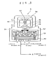
- the signal (voltage) from the signal generator 8 and said feedback signal are compared, and the difference is transmitted as an input electric current to the electro-hydraulic servo-valve 5, which moves the piston 41 in the direction to lessen the difference.
- the piston 41 of the vibration cylinder 4 is made to vibrate profiling the wave form of the signal from the signal generator 8.
- the signal desired to be generated from the generator 8, that is, the operation condition of the pile driver can be easily set by turning the adjusting dial (not shown) attached thereto.
- 3 is shown a two-stage, most typical electro-hydraulic servo-valve to facilitate comprehension of the work principle; if an actuator of greater capacity is to be controlled, a three-stage electro-hydraulic servo- valve can be adopted.
- a three-stage electro-hydraulic servo-valve the work principle that the output flow is controlled through displacement of the spool which is made to be proportional to the input electric current, is the same with the typical servo-valve described above.
Landscapes
- Engineering & Computer Science (AREA)
- Life Sciences & Earth Sciences (AREA)
- General Life Sciences & Earth Sciences (AREA)
- Mining & Mineral Resources (AREA)
- Paleontology (AREA)
- Civil Engineering (AREA)
- General Engineering & Computer Science (AREA)
- Structural Engineering (AREA)
- Mechanical Engineering (AREA)
- Placing Or Removing Of Piles Or Sheet Piles, Or Accessories Thereof (AREA)
- Operation Control Of Excavators (AREA)
Claims (3)
- Pfahlramme mit einem Rammgerät, das an dem Ende eines Arbeitsarms (12) einer geeigneten Baumaschine angeordnet ist, die als Basismaschine (11) dient, wobei das Rammgerät einen Rammvibrationszylinder (4), der an einem Befestigungsrahmen (1) gehalten ist, der an dem Ende des Arbeitsarms (12) befestigt wird, ferner ein Gegengewicht (2) an dem axialen Ende des Vibrationszylinders (4), das von dem Boden abgewandt ist, und eine Spanneinrichtung (6) zum Ergreifen eines zu rammenden Pfahls K an dem anderen axialen Ende des Vibrationszylinders (4), welches dem Boden zugewandt ist, und ferner ein Servosteuersystem aufweist, welches aus einem elektrohydraulischen Servoventil (5), das den Vibrationszylinder (4) betätigt und steuert, einem Kolbenverlagerungssensor (7), der die Verlagerung des Kolbens (41) des Vibrationszylinders (4) erfaßt, einem Signalgenerator (8), der Eingangssignale für das elektrohydraulische Servoventil (5) erzeugt, einem Rückkopplungssignalkreis (9), der das erfaßte Signal von dem Kolbenverlagerungssensor an das elektrohydraulische Servoventil (5) überträgt, und einem Servoverstärker (10) besteht, der das Signal von dem Signalgenerator (8) mit dem Signal von dem Kolbenverlagerungssensor (7) vergleicht,
dadurch gekennzeichnet,
daß die Anordnung, die den Vibratioszylinder (4), das Gegengewicht (2) und die Spanneinrichtung (6) enthält, von einem Halterahmen (3A) gehalten ist, der mit dem Befestigungsrahmen (1) über einen Puffergummi (3) verbunden ist, und daß die Spanneinrichtung (6) direkt mit dem Halterahmen (3A) verbunden ist. - Pfahlramme nach Anspruch 1,
dadurch gekennzeichnet, daß der Vibrationszylinder (4) an dem Befestigungsrahmen (1) auf solche Weise befestigt ist, daß die Austrittsseite des Kolbens (41) dem Boden zugewandt ist. - Pfahlramme nach Anspruch 1,
dadurch gekennzeichnet, daß der Vibrationszylinder (4) an dem Befestigungsrahmen (1) auf solche Weise befestigt ist, daß die Austrittsseite des Kolbens (41) der dem Boden entgegengesetzten Richtung zugewandt ist.
Applications Claiming Priority (2)
| Application Number | Priority Date | Filing Date | Title |
|---|---|---|---|
| JP82184/90 | 1990-03-29 | ||
| JP8218490 | 1990-03-29 |
Publications (2)
| Publication Number | Publication Date |
|---|---|
| EP0449286A1 EP0449286A1 (de) | 1991-10-02 |
| EP0449286B1 true EP0449286B1 (de) | 1994-12-07 |
Family
ID=13767358
Family Applications (1)
| Application Number | Title | Priority Date | Filing Date |
|---|---|---|---|
| EP91104984A Expired - Lifetime EP0449286B1 (de) | 1990-03-29 | 1991-03-28 | Pfahlramme |
Country Status (5)
| Country | Link |
|---|---|
| US (1) | US5168938A (de) |
| EP (1) | EP0449286B1 (de) |
| JP (1) | JP2729969B2 (de) |
| KR (1) | KR100218997B1 (de) |
| DE (1) | DE69105574T2 (de) |
Families Citing this family (20)
| Publication number | Priority date | Publication date | Assignee | Title |
|---|---|---|---|---|
| KR100440729B1 (ko) * | 2001-05-16 | 2004-07-19 | 김억수 | 굴삭기용 항타발장치 |
| NZ528332A (en) * | 2003-09-22 | 2006-04-28 | Ramet Holdings Ltd | Impact driver for driving poles, piles or posts including linear induction motor |
| US7296475B2 (en) * | 2005-03-18 | 2007-11-20 | Conner Charles C | Displacement instrument for determining the modulus of a material |
| US7080958B1 (en) | 2005-04-27 | 2006-07-25 | International Construction Equipment, Inc. | Vibratory pile driver/extractor with two-stage vibration/tension load suppressor |
| US20080072656A1 (en) * | 2006-03-18 | 2008-03-27 | Conner Charles C | Displacement instrument |
| WO2008033139A1 (en) * | 2006-09-15 | 2008-03-20 | Conner Charles C | Pressure transducer for measuring hydraulic breaker displacement and determining aggregate modulus during compaction |
| EP2067533B2 (de) * | 2007-12-06 | 2016-12-07 | ABI Anlagentechnik-Baumaschinen-Industriebedarf Maschinenfabrik und Vertriebsgesellschaft mbH | Schwingungserzeuger für ein Vibrationsrammgerät |
| EP2085148B1 (de) * | 2008-01-29 | 2013-09-18 | ABI Anlagentechnik-Baumaschinen-Industriebedarf Maschinenfabrik und Vertriebsgesellschaft mbH | Schwingungserzeuger für ein Vibrationsrammgerät |
| DE102014003117B4 (de) * | 2014-03-11 | 2017-09-28 | Thyssenkrupp Ag | Vorrichtung sowie Verfahren zum Aufnehmen von Rammgut und/oder Einbringen von Rammgut in den Boden |
| FI20140081A7 (fi) | 2014-03-19 | 2015-09-20 | Movax Oy | Työkoneeseen liitettävä iskulaite |
| NL2013871B1 (nl) * | 2014-06-10 | 2016-05-03 | Cape Holland Holding B V | Trilinrichting en werkwijze voor het in een ondergrond brengen van een funderingselement. |
| CN105625417B (zh) * | 2016-01-30 | 2017-06-23 | 周兆弟 | 打桩机变截面打桩控制方法及其系统 |
| DK3417951T3 (da) * | 2017-06-19 | 2022-07-04 | Eurodrill Gmbh | Anordning og fremgangsmåde til generering af slagimpulser eller svingninger til en byggemaskine |
| BR112020020492A2 (pt) * | 2018-04-24 | 2021-01-12 | Resemin S.A. | Jumbo eletro-hidráulico |
| CN109024544B (zh) * | 2018-07-02 | 2020-09-15 | 中国铁路总公司 | 湿陷性黄土隧道基底液压高频挤密处理方法 |
| KR200491468Y1 (ko) * | 2018-08-06 | 2020-04-13 | 춘 산 왕 | 항타기(杭打機-말뚝 박는 기계)방열구조 |
| US11338326B2 (en) * | 2019-04-07 | 2022-05-24 | Resonance Technology International Inc. | Single-mass, one-dimensional resonant driver |
| PT4214366T (pt) * | 2020-09-17 | 2025-09-30 | Cape Holland Holding B V | Dispositivo de fixação para um dispositivo de vibração para inserir um elemento de fundação, dispositivo de vibração fornecido com o mesmo e método para o mesmo |
| CN112761151B (zh) * | 2021-01-23 | 2025-02-14 | 山东临工工程机械有限公司 | 冲击式打桩机构及其打桩机 |
| CN112761152B (zh) * | 2021-01-23 | 2024-11-29 | 山东临工工程机械有限公司 | 打桩机构及其打桩机 |
Citations (1)
| Publication number | Priority date | Publication date | Assignee | Title |
|---|---|---|---|---|
| JPH06172121A (ja) * | 1992-12-07 | 1994-06-21 | Kazumasa Muratsu | 歯牙補修材及び人工歯牙 |
Family Cites Families (7)
| Publication number | Priority date | Publication date | Assignee | Title |
|---|---|---|---|---|
| GB1258060A (de) * | 1968-10-11 | 1971-12-22 | ||
| SE365418B (de) * | 1973-02-01 | 1974-03-25 | Ilmeg Ab | |
| US4056123A (en) * | 1973-09-26 | 1977-11-01 | Nihon Spindle Seizo Kabushiki Kaisha | Hydraulic oscillator |
| DE2850225C2 (de) * | 1978-11-20 | 1983-12-22 | Rudolf Hausherr & Söhne GmbH & Co KG, 4322 Sprockhövel | Vorrichtung zur Herstellung von Bohrungen in Gestein, Erdreich und dgl. |
| JPS5827372B2 (ja) * | 1979-03-31 | 1983-06-09 | 淳三 溝「淵」 | 振動式杭打杭抜機 |
| US4487109A (en) * | 1982-03-30 | 1984-12-11 | Sundstrand Corporation | Electro-hydraulic control system for a power drive unit |
| JPS63189522A (ja) * | 1987-01-30 | 1988-08-05 | Takahashi Eng:Kk | 杭打ち装置 |
-
1991
- 1991-03-01 JP JP3059745A patent/JP2729969B2/ja not_active Expired - Fee Related
- 1991-03-20 US US07/672,269 patent/US5168938A/en not_active Expired - Fee Related
- 1991-03-27 KR KR1019910004723A patent/KR100218997B1/ko not_active Expired - Fee Related
- 1991-03-28 EP EP91104984A patent/EP0449286B1/de not_active Expired - Lifetime
- 1991-03-28 DE DE69105574T patent/DE69105574T2/de not_active Expired - Fee Related
Patent Citations (1)
| Publication number | Priority date | Publication date | Assignee | Title |
|---|---|---|---|---|
| JPH06172121A (ja) * | 1992-12-07 | 1994-06-21 | Kazumasa Muratsu | 歯牙補修材及び人工歯牙 |
Also Published As
| Publication number | Publication date |
|---|---|
| KR910017031A (ko) | 1991-11-05 |
| JP2729969B2 (ja) | 1998-03-18 |
| JPH05306521A (ja) | 1993-11-19 |
| KR100218997B1 (ko) | 1999-09-01 |
| US5168938A (en) | 1992-12-08 |
| DE69105574D1 (de) | 1995-01-19 |
| DE69105574T2 (de) | 1995-05-04 |
| EP0449286A1 (de) | 1991-10-02 |
Similar Documents
| Publication | Publication Date | Title |
|---|---|---|
| US5168938A (en) | Pile driver | |
| US6705079B1 (en) | Apparatus for controlling bounce of hydraulically powered equipment | |
| JP2006177561A (ja) | 電動油圧式比例制御弁組立体 | |
| FR2483487A1 (fr) | Systeme de commande hydraulique pour machines de travaux automotrices tout-terrain | |
| CN114294273A (zh) | 液压控制系统、拖拉机和液压控制方法 | |
| JP2006219975A (ja) | 移動機械のための半能動走行制御 | |
| US3625483A (en) | Automatic leveling system for blast hole drills and the like | |
| CN213802704U (zh) | 一种液压举升控制系统 | |
| US4802787A (en) | Electrical control system | |
| US3473547A (en) | Electromechanical driver for hydraulic valve and the like | |
| JP3044240B2 (ja) | 杭打ち装置 | |
| JPH03170275A (ja) | ピストン振動数制御装置 | |
| GB2201262A (en) | Servo-valve control | |
| JPS629878A (ja) | 液圧式打撃装置 | |
| US3486568A (en) | Hydraulic impact apparatus | |
| JP2793686B2 (ja) | 杭打ち制御装置 | |
| KR20000003487U (ko) | 건설중장비의 유압펌프 토출유량제어장치 | |
| EP0276845B1 (de) | Pfahlramme | |
| SU1553631A1 (ru) | Бульдозер | |
| JP3333334B2 (ja) | 作業車両の懸架装置 | |
| KR0181258B1 (ko) | 중장비의 전후 진동감쇠 장치 | |
| WO1996032546A1 (en) | Bucket type digging machine | |
| SU1557538A1 (ru) | Источник сейсмических сигналов ударного типа | |
| JPS61202614A (ja) | 水田作業機の接地圧力検出装置 | |
| SU1640297A2 (ru) | Рабочее оборудование экскаватора |
Legal Events
| Date | Code | Title | Description |
|---|---|---|---|
| PUAI | Public reference made under article 153(3) epc to a published international application that has entered the european phase |
Free format text: ORIGINAL CODE: 0009012 |
|
| AK | Designated contracting states |
Kind code of ref document: A1 Designated state(s): CH DE FR GB IT LI NL |
|
| 17P | Request for examination filed |
Effective date: 19920325 |
|
| 17Q | First examination report despatched |
Effective date: 19920504 |
|
| GRAA | (expected) grant |
Free format text: ORIGINAL CODE: 0009210 |
|
| AK | Designated contracting states |
Kind code of ref document: B1 Designated state(s): CH DE FR GB IT LI NL |
|
| REF | Corresponds to: |
Ref document number: 69105574 Country of ref document: DE Date of ref document: 19950119 |
|
| ITF | It: translation for a ep patent filed | ||
| ET | Fr: translation filed | ||
| PLBE | No opposition filed within time limit |
Free format text: ORIGINAL CODE: 0009261 |
|
| STAA | Information on the status of an ep patent application or granted ep patent |
Free format text: STATUS: NO OPPOSITION FILED WITHIN TIME LIMIT |
|
| 26N | No opposition filed | ||
| PGFP | Annual fee paid to national office [announced via postgrant information from national office to epo] |
Ref country code: FR Payment date: 19980319 Year of fee payment: 8 |
|
| PGFP | Annual fee paid to national office [announced via postgrant information from national office to epo] |
Ref country code: GB Payment date: 19980320 Year of fee payment: 8 |
|
| PGFP | Annual fee paid to national office [announced via postgrant information from national office to epo] |
Ref country code: NL Payment date: 19980331 Year of fee payment: 8 |
|
| PGFP | Annual fee paid to national office [announced via postgrant information from national office to epo] |
Ref country code: DE Payment date: 19980527 Year of fee payment: 8 |
|
| PGFP | Annual fee paid to national office [announced via postgrant information from national office to epo] |
Ref country code: CH Payment date: 19980617 Year of fee payment: 8 |
|
| PG25 | Lapsed in a contracting state [announced via postgrant information from national office to epo] |
Ref country code: GB Free format text: LAPSE BECAUSE OF NON-PAYMENT OF DUE FEES Effective date: 19990328 |
|
| PG25 | Lapsed in a contracting state [announced via postgrant information from national office to epo] |
Ref country code: LI Free format text: LAPSE BECAUSE OF NON-PAYMENT OF DUE FEES Effective date: 19990331 Ref country code: CH Free format text: LAPSE BECAUSE OF NON-PAYMENT OF DUE FEES Effective date: 19990331 |
|
| PG25 | Lapsed in a contracting state [announced via postgrant information from national office to epo] |
Ref country code: NL Free format text: LAPSE BECAUSE OF NON-PAYMENT OF DUE FEES Effective date: 19991001 |
|
| REG | Reference to a national code |
Ref country code: CH Ref legal event code: PL |
|
| GBPC | Gb: european patent ceased through non-payment of renewal fee |
Effective date: 19990328 |
|
| PG25 | Lapsed in a contracting state [announced via postgrant information from national office to epo] |
Ref country code: FR Free format text: LAPSE BECAUSE OF NON-PAYMENT OF DUE FEES Effective date: 19991130 |
|
| NLV4 | Nl: lapsed or anulled due to non-payment of the annual fee |
Effective date: 19991001 |
|
| REG | Reference to a national code |
Ref country code: FR Ref legal event code: ST |
|
| PG25 | Lapsed in a contracting state [announced via postgrant information from national office to epo] |
Ref country code: DE Free format text: LAPSE BECAUSE OF NON-PAYMENT OF DUE FEES Effective date: 20000101 |
|
| PG25 | Lapsed in a contracting state [announced via postgrant information from national office to epo] |
Ref country code: IT Free format text: LAPSE BECAUSE OF NON-PAYMENT OF DUE FEES;WARNING: LAPSES OF ITALIAN PATENTS WITH EFFECTIVE DATE BEFORE 2007 MAY HAVE OCCURRED AT ANY TIME BEFORE 2007. THE CORRECT EFFECTIVE DATE MAY BE DIFFERENT FROM THE ONE RECORDED. Effective date: 20050328 |