EP0449531B1 - Rotoren - Google Patents
Rotoren Download PDFInfo
- Publication number
- EP0449531B1 EP0449531B1 EP91302531A EP91302531A EP0449531B1 EP 0449531 B1 EP0449531 B1 EP 0449531B1 EP 91302531 A EP91302531 A EP 91302531A EP 91302531 A EP91302531 A EP 91302531A EP 0449531 B1 EP0449531 B1 EP 0449531B1
- Authority
- EP
- European Patent Office
- Prior art keywords
- rotor
- rotation
- elastomeric
- driving member
- axis
- Prior art date
- Legal status (The legal status is an assumption and is not a legal conclusion. Google has not performed a legal analysis and makes no representation as to the accuracy of the status listed.)
- Expired - Lifetime
Links
- 230000033001 locomotion Effects 0.000 claims description 31
- 230000008878 coupling Effects 0.000 claims description 10
- 238000010168 coupling process Methods 0.000 claims description 10
- 238000005859 coupling reaction Methods 0.000 claims description 10
- 230000000712 assembly Effects 0.000 description 14
- 238000000429 assembly Methods 0.000 description 14
- 238000003756 stirring Methods 0.000 description 5
- 241000239290 Araneae Species 0.000 description 2
- 230000005540 biological transmission Effects 0.000 description 2
- 230000006835 compression Effects 0.000 description 2
- 238000007906 compression Methods 0.000 description 2
- 230000000694 effects Effects 0.000 description 2
- 238000010008 shearing Methods 0.000 description 2
- 230000002411 adverse Effects 0.000 description 1
- 230000001627 detrimental effect Effects 0.000 description 1
- 238000006073 displacement reaction Methods 0.000 description 1
- 239000013536 elastomeric material Substances 0.000 description 1
- 238000012423 maintenance Methods 0.000 description 1
- 239000002184 metal Substances 0.000 description 1
- 238000012986 modification Methods 0.000 description 1
- 230000004048 modification Effects 0.000 description 1
- 230000000717 retained effect Effects 0.000 description 1
Images


Classifications
-
- F—MECHANICAL ENGINEERING; LIGHTING; HEATING; WEAPONS; BLASTING
- F16—ENGINEERING ELEMENTS AND UNITS; GENERAL MEASURES FOR PRODUCING AND MAINTAINING EFFECTIVE FUNCTIONING OF MACHINES OR INSTALLATIONS; THERMAL INSULATION IN GENERAL
- F16D—COUPLINGS FOR TRANSMITTING ROTATION; CLUTCHES; BRAKES
- F16D3/00—Yielding couplings, i.e. with means permitting movement between the connected parts during the drive
- F16D3/50—Yielding couplings, i.e. with means permitting movement between the connected parts during the drive with the coupling parts connected by one or more intermediate members
- F16D3/70—Yielding couplings, i.e. with means permitting movement between the connected parts during the drive with the coupling parts connected by one or more intermediate members comprising elastic elements arranged in holes in one coupling part and surrounding pins on the other coupling part
-
- B—PERFORMING OPERATIONS; TRANSPORTING
- B64—AIRCRAFT; AVIATION; COSMONAUTICS
- B64C—AEROPLANES; HELICOPTERS
- B64C27/00—Rotorcraft; Rotors peculiar thereto
- B64C27/32—Rotors
- B64C27/35—Rotors having elastomeric joints
-
- B—PERFORMING OPERATIONS; TRANSPORTING
- B64—AIRCRAFT; AVIATION; COSMONAUTICS
- B64C—AEROPLANES; HELICOPTERS
- B64C27/00—Rotorcraft; Rotors peculiar thereto
- B64C27/32—Rotors
- B64C27/37—Rotors having articulated joints
- B64C27/41—Rotors having articulated joints with flapping hinge or universal joint, common to the blades
Definitions
- This invention relates to rotors and is particularly concerned with rotors having an axis of rotation and a plurality of radially extending rotor blades rotating in a plane of rotation which can be tilted in any direction relative the axis of rotation.
- Such rotors are sometimes knawn as gimbal rotors and can be used in conventional helicopters as either a main sustaining rotor or an anti-torque rotor, and as the sustaining rotor/propeller in tilt wing or tilt rotor VTOL aircraft.
- EP-A-0221372 describes a constant velocity joint suitable for use in such rotors and comprising six elastomeric bearing assemblies located concentrically around an axis of rotation and with their axes parallel to the axis of rotation.
- Each elastomeric bearing assembly comprises concentrically arranged cylindrical and spherical elastomeric bearing portions and this may cause difficulty in obtaining optimum properties in all planes of operation and may require large bearings that may be impractical in an operational configuration.
- US-A-4804352 describes a link type coupling which can be used for correcting a drive shaft to a rotor hub in an aircraft and having a plurality of links arranged tangentially with respect to driving and driven members and connected thereto by spherical elastomeric bearings at each end. Each link is attached to the driving member through a stub shaft extending generally tangentially of the driving member. In such an arrangement, all of the highly complex movements necessary to permit tilting of the rotor head in any direction relative the axis of rotation must be accommodated in the individual spherical bearings which must also accommodate all of the torque loads.
- the present invention aims to overcome the problem of the prior art arrangements.
- this invention provides a rotor having a rotor head supporting a plurality of radially extending rotor blades for rotation about an axis and comprising a driving member rotationally fixed adjacent one end of a drive shaft and having a plurality of equi-spaced drive pins, wherein said driving member has at least three drive pins extending radially of the axis of rotation and in a plane of rotation perpendicular to the axis, each drive pin locating in an elastomeric bearing assembly having a spherical elastomeric bearing centred on the drive pin and an elastomeric shear bearing located in the plane of rotation and oriented parallel to the axis of rotation, a gimbal housing attached to the elastomeric shear bearings and supporting a rotor yoke for attachment of the rotor blades, a spherical elastomeric thrust bearing attached to the gimbal housing with its geometral centre located at an intersection of the axis
- the driving member may have an odd number of drive pins and in one embodiment the driving member may have three drive pins.
- the drive shaft may be located concentrically within a tubular rotor drive shaft and an inner end of the drive shaft may be attached internally of the rotor drive shaft by flexible coupling means capable of transmitting torque whilst permitting relative axial movements.
- the flexible coupling means may comprise mated axial splines and in such an embodiment the spherical elastomeric thrust bearing may be attached to the end of the rotor drive shaft.
- the driving member may have an even number of drive pins and in one embodiment the driving member may have six drive pins.
- the driving member and said spherical elastomeric thrust bearing may be rotationally fixed to the upper end of a rotor drive shaft.
- each elastomeric shear bearing comprises two elastomeric shear bearings located one at each side of the spherical elastomeric bearing.
- the rotor yoke and attached rotor blades may be located coincident with the plane of rotation of the driving member.
- the invention also provides a rotor having a rotor head supporting a plurality of radially extending rotor blades for rotation about an axis, comprising a driving number rotationally fixed adjacent an outer end of a drive shaft located concentrically within a tubular rotor drive shaft with an inner end attached internally of the rotor drive shaft by flexible coupling means capable of transmitting torque and permitting relative axial movements, said driving member having three equi-spaced drive pins extending radially of the axis of rotation and in a plane of rotation perpendicular to the axis, each drive pin locating in an elastomeric bearing assembly having a spherical elastomeric bearing centred on the drive pin and two elastomeric shear bearings located one at each side of the spherical bearing in the plane of rotation and oriented parallel to the axis of rotation, a gimbal housing attached to the elastomeric shear bearings and supporting a rotor yoke for attachment of the
- a rotor 11 for a helicopter anti-torque rotor comprises a tubular rotor drive shaft 12 mounted on spaced-apart bearings 13 and 14 in a gear case 15 for rotation about an axis 16.
- a lower end of the shaft 12 is rotationally fixed to an output gear 17 and an upper end protrudes from the gear case 15 to support a rotor head 18 at its upper end as will be described in detail hereinafter.
- a lower end of an inner tubular drive shaft 19 is connected internally of the lower end of shaft 12 by flexible coupling means 20 comprising, in the illustrated embodiment, mated axial splines 21 permitting limited relative axial movements.
- the outer surface of drive shaft 19 is spaced-apart from the inner surface of shaft 12, and the inner shaft 19 protrudes from an upper end thereof to support a driving member 22 rotationally fixed to the inner shaft 19 by mated splines 23.
- Driving member 22 includes three equi-spaced drive pins 24 extending radially of the axis of rotation 16 and located in a plane of rotation 25 that is perpendicular to the axis of rotation 16.
- Each drive pin 24 is connected to an elastomeric bearing assembly 26 attached to a gimbal housing 27 having a flanged lower end attached to a central flange 28 of a spherical elastomeric thrust bearing 29 which is rotationally fixed to the upper end of rotor drive shaft 12 and retained by a retaining nut 30.
- the thrust bearing 29 has a geometral centre 29 a located at the intersection between the rotational axis 16 and the plane of rotation 25 of the driving member 22.
- Gimbal housing 27 also supports through an attachment ring 31 an annular yoke 32 which with the rotor untilted as shown in Figure 1 is coincident with the plane of rotation 25, and is used to attach a plurality of radially extending rotor blades (not shown) as hereinafter described in more detail in respect of the other embodiments. It will be noted in this embodiment that a normal untilted plane of rotation 35 of the rotor yoke 32 and, therefore, its attached rotor blades is coincident with the plane of rotation 25 of the driving member 22.
- Elastomeric bearings are well known and comprise layers of an elastomeric material bonded to and separated by a series of non-extensible members such as metal shims.
- Each elastomeric bearing assembly 26 comprises a spherical elastomeric bearing 33 having an inner attachment sleeve 53 rotationally fixed to the drive pin 24 by bolts 54 ( Figure 2).
- An inner elastomeric layer of bearing 33 is bonded to an external spherical convex surface 53 a of sleeve 53 and an outer elastomeric layer is bonded to an inner concave surface 55 a of an outer annular attachment member 55.
- the spherical bearing 33 is located between a pair of flat elastomeric shear bearings 34 located one at each side of the spherical bearing in the plane of rotation 25 and oriented in a plane parallel to the axis of rotation 16.
- each of bearings 34 is bonded to an external planar surface 55 b of outer attachment member 55 and an outer elastomeric layer is bonded to a planar surface 56 a of an attachment bracket 56 which is attached in turn to the gimbal housing 27.
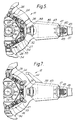
- driving member 22 has six equi-spaced radially extending drive pins 24 (three only being shown) each located in an elastomeric bearing assembly 26 constructed similarly to that of the previous embodiment.
- the bearing assemblies 26 are attached to an annular gimbal housing 27 which supports a two part spherical elastomeric thrust bearing 29 having a geometral centre 29 a located at the intersection of the axis of rotation 16 and plane of rotation 25 of the driving member 22 which is perpendicular thereto.
- the driving member 22 is rotationally fixed to the external surface of the rotor drive shaft 12 by mated splines 36.
- the thrust bearing 29 is also secured to the rotor drive shaft 12 as before.
- the gimbal housing 27 again supports a rotor yoke 32 which in this embodiment is located at a lower end thereof so that its plane of rotation 35 is spaced-apart axially from the plane of rotation 25 of the driving member 22.
- Rotor yoke 32 includes four radially extending integral arm 37 each including an intermediate flexible portion 38 which is flexible in a plane perpendicular to the plane of rotation 35.
- Inner and outer apertures 39 and 40 are located through each arm 37, the inner aperture 39 housing a spherical elastomeric bearing 41 centred on a spigot 42 attached to yoke 32 and supporting an inner end of a torque tube 43.
- a pitch change arm 44 is attached to the inner end of the torque tube 43 for connection during operation to blade pitch control means (not shown) in conventional manner.
- a locating spigot 45 on an inner surface of outer aperture 40 is located in a journal bearing 46 supported in a pillar 47 which supports the outer end of torque tube 43 and also attaches the root end 48 of a rotor blade (not shown).
- a cylindrical elastomeric bearing 49 is located between the pillar 47 and an outer surface of outer aperture 40.
- the rotor yoke 32 is supported at the centre of gimbal housing 27 so that the plane of rotation 35 of the untilted rotor is coincident with the plane of rotation 25 of the driving member 22 which again intersects the geometral centre 29 a of bearing 29. Attachment of the four rotor blades via root ends 48 is identical to that previously described with reference to the embodiment of Figures 4 and 5.
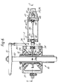
- This embodiment is configured particularly for use as an anti-torque rotor for a helicopter and to that end the pitch control arms 44 extend forwardly from an attachment to the torque tube 43 for connection to the ends of pitch control rods 50 carried by a control spider 51 secured to the end of a pitch control spindle 52 located concentrically through the rotor drive shaft 12.
- FIG 8 is similar to Figure 3 and gives more detail of the elastomeric bearing assemblies 26 used in the embodiments of Figures 4 to 7 inclusive.
- each of the six drive pins 24 is located centrally of the spherical elastomeric bearing 33 which in turn is connected between the two elastomeric shear bearings 34 located in the plane of rotation 25 and oriented parallel to the axis of rotation 16.
- the elastomeric shear bearings 34 are attached to the gimbal housing 27 which is again connected to a spherical elastomeric thrust bearing 29 supported on the rotor drive shaft 12.
- torque is transmitted from a transmission system through the inner drive shaft 19 of the embodiment of Figures 1 to 3 and through the rotor drive shaft 12 in the embodiments of Figures 4 to 8 inclusive to rotate the driving member 22 about the axis 16.
- Torque is transmitted through the spherical bearing 33 and shear bearings 34 of the elastomeric bearing assemblies 26 to the gimbal housing 27 and thence through the rotor yoke 32 to rotate the attached rotor blades.
- Centrifugal forces are transmitted through the cylindrical elastomeric bearings 49 into the integral arm 37 of the rotor yoke 32.
- pitch control means e.g. rods 50, spider 51 and spindle 52, and pitch change arm 44 to rotate the torque tubes 43 on the bearings 41 and 46, and accommodated through shear movement of the cylindrical elastomeric bearing 49.
- the present invention permits tilting of the plane of rotation 35 of the rotor yoke 32 and attached rotor blades in any direction about the geometral centre 29 a of the thrust bearing 29, stiffness being provided during tilting by the elastomeric bearing assemblies 26 and the elastomeric thrust bearing 29. Furthermore, during the misalignment that occurs in tilting the plane of rotation 35 the correction between driving member 22 and elastomeric bearing assemblies 26 provide a near constant velocity joint to minimise the adverse effects of Coriolis force.
- tilting of the gimbal housing 27 relative to the drive shaft (12 or 19) is accommodated by the spherical elastomeric thrust bearing 29 which also maintains a desired focal point about which tilting occurs coincident with its geometral centre 29 a .
- Tilting of the gimbal housing 27 relative to the three or six pin driving member 22 is accommodated in the elastomeric bearing assemblies 26 whilst maintaining an efficient load path for torque transmission.
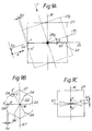
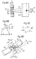
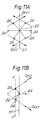
- Figures 9 to 11 comprise generally schematic illustrations of the complex movements accommodated in the elastomeric bearing assemblies 26 and the elastomeric thrust bearing 29 during tilting of the gimbal housing 27 relative to the axis of rotation 16 of the rotor drive shaft 12.
- FIG 9A is a schematic side view of a rotor according to this invention.
- Gimbal housing 27 is shown in an undeflected state in full line and tilted forward in broken line 27 a through angle ⁇ about a lateral axis 57 coincident with focal point 29 a and perpendicular to axis 16.
- the driving member 22 foreshortens when viewed along arrow F (see also Figure 9B) by an amount ⁇ F and that there is a simultaneous out of plane movement between points X and X1 of magnitude ⁇ S when viewed along arrow G (see also Figure 9C).
- ⁇ S is accommodated by shearing of the elastomeric shear bearings 34 in a direction parallel to the axis of rotation 16 whilst the foreshortening ⁇ F is accommodated by shearing of the elastomeric shear bearings 34 of the elastomeric bearing assemblies 26 in a direction perpendicular to the axis of rotation.
- the radial component ⁇ FYR is accommodated by shear motion of the elastomeric shear bearings 34 in the same manner as the radial motion X'X; however the tangential component ⁇ FYT must be accommodated by compression of the elastomeric shear bearings 34 and the spherical elastomeric bearing 33 of the elastomeric bearing assemblies 26 as indicated between the full line and broken line positions in Figure 10D.
- elastomeric bearings leads to low maintenance requirements and benign failure characteristics.
- the arrangements possess tuneable and non-linear flapping stiffness characteristics which, in a main sustaining rotor will permit optimisation of aircraft handling characteristics and in an anti-torque rotor may eliminate the normal requirement for external gust locks.
- the use of separate elastomeric spherical and shear bearings in the elastomeric bearing assemblies 26 facilitates accurate tailoring of the operational requirements in all planes of operation and minimises the required size and weight of the assemblies.
- the three drive pin arrangement of Figures 1 to 3 inclusive is preferred because it provides a rotor having a law parts count making it simple and lightweight.
- the six drive pin arrangement of Figures 4 to 7 inclusive is preferred because it minimises rotor moment and torque fluctuations that arise due to alternate "locking" and “unlocking" of the elastomeric shear bearings 34 when operating respectively in compression and shear during rotation of the rotor.
- the flexible coupling means 20 could also be arranged to provide for the necessary "stirring" motion of the upper end of the inner tubular drive shaft 19 by comprising "barrelled” splines or any other suitable form of flexible coupling.
- rotors according to this invention can have any number of drive pins 24 other than the alternative six drive pin arrangements herein described and illustrated.
Landscapes
- Engineering & Computer Science (AREA)
- Mechanical Engineering (AREA)
- Aviation & Aerospace Engineering (AREA)
- General Engineering & Computer Science (AREA)
- Support Of The Bearing (AREA)
- Toys (AREA)
- Pivots And Pivotal Connections (AREA)
Claims (12)
- Rotor (11) mit einem Rotorkopf, der eine Mehrzahl von sich radial erstreckenden Rotorblättern zur Drehung um eine Achse (16) trägt und ein Antriebsteil (22) aufweist, das benachbart zu einem Ende einer Antriebswelle (19) gegen Verdrehen fixiert ist, wobei das besagte Antriebsteil (22) eine Mehrzahl von einen gleichmäßigen Abstand aufweisenden Antriebszapfen (24) hat, dadurch gekennzeichnet, daß das besagte Antriebsteil (22) wenigstens drei Antriebszapfen (24) hat, die sich radial von der Drehachse (16) und in einer Drehebene (25) senkrecht zu besagter Achse (16) erstrecken, wobei jeder Antriebszapfen (24) in einer gummiartigen Lageranordnung (26) sitzt, die eine sphärische, gummiartige Lagerung (33) hat, die auf den Antriebszapfen (24) zentriert ist, und eine gummiartige Scherungslagerung (34), die in der Drehebene angeordnet ist und parallel zur Drehachse (16) ausgerichtet ist, wobei ein Kardangehäuse (27) an den gummiartigen Scherungslagerungen (34) befestigt ist und ein Rotorjoch (32) zur Befestigung der Rotorblätter trägt, eine sphärische, gummiartige Schublagerung (29) am Kardangehäuse (27) befestigt ist, deren geometrisches Zentrum (29a) am Schnittpunkt der Drehachse (16) und der Drehebene (25) des Antriebsteils (22) angeordnet ist, wodurch der Rotor (11) im Betrieb in jede Richtung um das besagte Zentrum gekippt werden kann.
- Rotor nach Anspruch 1, dadurch gekennzeichnet, daß das besagte Antriebsteil (22) eine ungerade Anzahl Antriebszapfen (24) hat.
- Rotor nach Anspruch 1 oder 2, dadurch gekennzeichnet, daß das besagte Antriebsteil (22) drei Antriebszapfen (24) hat.
- Rotor nach Anspruch 2 oder 3, dadurch gekennzeichnet, daß die besagte Antriebswelle (19) konzentrisch innerhalb einer rohrförmigen Rotorantriebswelle (12) angeordnet ist und ein inneres Ende der Antriebswelle (19) innerhalb der Rotorantriebswelle (12) über flexible Kupplungsmittel (20) befestigt ist, die ein Drehmoment übertragen können, wobei sie axiale Relativbewegungen zulassen.
- Rotor nach Anspruch 4, dadurch gekennzeichnet, daß das besagte flexible Kupplungsmittel (20) in Eingriff stehende, axiale Keilnuten umfaßt.
- Rotor nach Anspruch 4 oder 5, dadurch gekennzeichnet, daß die besagte sphärische, gummiartige Schublagerung (29) am Ende der Rotorantriebswelle (12) befestigt ist.
- Rotor nach Anspruch 1, dadurch gekennzeichnet, daß das besagte Antriebsteil (22) eine gerade Anzahl von Antriebszapfen (24) hat.
- Rotor nach Anspruch 1 oder 7, dadurch gekennzeichnet, daß das besagte Antriebsteil (22) sechs Antriebzapfen (24) hat.
- Rotor nach Anspruch 7 oder 8, dadurch gekennzeichnet, daß das besagte Antriebsteil (22) und die besagte sphärische, gummiartige Schublagerung (29) gegen Verdrehen auf einer Rotorantriebswelle (12) fixiert sind.
- Rotor nach einem der vorangehenden Ansprüche, dadurch gekennzeichnet, daß jede gummiartige Schublagerung (34) zwei gummiartige Schublagerungen (34) umfaßt, die jeweils auf einer Seite der sphärischen, gummiartigen Lagerung (33) angeordnet sind.
- Rotor nach einem der vorangehenden Ansprüche, dadurch gekennzeichnet, daß die Stellung des Rotorjochs (32), wenn der Rotor nicht gekippt ist, mit der Drehebene (25) des Antriebsteils (22) zusammenfällt.
- Rotor (11) mit einem Rotorkopf, der eine Mehrzahl von sich radial erstreckenden Rotorblättern zur Drehung um eine Achse (16) trägt und ein Antriebsteil (22) aufweist, das benachbart zu einem Ende einer Antriebswelle (19) gegen Verdrehen fixiert ist, dadurch gekennzeichnet, daß die besagte Antriebswelle (19) konzentrisch innerhalb einer rohrförmigen Rotorantriebswelle (12) angeordnet ist, wobei ein inneres Ende innerhalb der Rotorantriebswelle (12) durch flexible Kupplungsmittel (20) befestigt sind, die Drehmoment übertrager können und axiale Relativbewegungen zulassen, wobei das besagte Antriebsteil (22) drei einen gleichen gegenseitigen Abstand aufweisende Antriebszapfen (24) hat, die sich radial von der Drehachse (16) und in einer Drehebene (25) senkrecht zur Achse (16) erstrecken, jeder Antriebszapfen (24) in einer gummiartigen Lagerungsanordnung (26) sitzt, die eine sphärische, gummiartige Lagerung (33) hat, die auf den Antriebszapfen (24) zentriert ist, und zwei gummiartige Schublagerungen (34), die jeweils auf einer Seite der sphärischen Lagerung (33) in der Drehebene (25) liegen und parallel zur Drehachse (16) ausgerichtet sind, ein Kardangehäuse (27) an den gummiartigen Schublagerungen (34) befestigt ist und ein Rotorjoch (32) zur Befestigung der Rotorblätter trägt, und wobei eine sphärische, gummiartige Schublagerung (29) am Kardangehäuse (27) befestigt ist, die ihr geometrisches Zentrum (29a) auf dem Schnittpunkt der Drehachse (16) und der Drehebene (25) des Antriebsteils (22) hat, wodurch der Rotor (11) im Betrieb in jeder Richtung um das Zentrum gekippt werden kann.
Applications Claiming Priority (2)
| Application Number | Priority Date | Filing Date | Title |
|---|---|---|---|
| GB909006668A GB9006668D0 (en) | 1990-03-24 | 1990-03-24 | Rotors |
| GB9006668 | 1990-03-24 |
Publications (2)
| Publication Number | Publication Date |
|---|---|
| EP0449531A1 EP0449531A1 (de) | 1991-10-02 |
| EP0449531B1 true EP0449531B1 (de) | 1994-01-19 |
Family
ID=10673230
Family Applications (1)
| Application Number | Title | Priority Date | Filing Date |
|---|---|---|---|
| EP91302531A Expired - Lifetime EP0449531B1 (de) | 1990-03-24 | 1991-03-22 | Rotoren |
Country Status (5)
| Country | Link |
|---|---|
| US (1) | US5145321A (de) |
| EP (1) | EP0449531B1 (de) |
| JP (1) | JP2919104B2 (de) |
| DE (1) | DE69101015T2 (de) |
| GB (1) | GB9006668D0 (de) |
Families Citing this family (17)
| Publication number | Priority date | Publication date | Assignee | Title |
|---|---|---|---|---|
| US5620305A (en) * | 1995-03-20 | 1997-04-15 | The Boeing Company | Hub for rotary wing aircraft |
| US6394387B1 (en) * | 2000-12-22 | 2002-05-28 | Pratt & Whitney Canada Corp. | Rotor shaft support and drive arrangement |
| FR2837462B1 (fr) | 2002-03-20 | 2004-05-28 | Eurocopter France | Rotor de giravion a entrainement homocinetique |
| FR2837784B1 (fr) | 2002-03-28 | 2004-05-28 | Eurocopter France | Rotor de giravion a entrainement homocinetique avec differentiel de partage de couple |
| EP1704345B1 (de) | 2004-01-15 | 2012-03-07 | Lord Corporation | Drehflügelflugzeugstangenkopf und verfahren zur herstellung eines hubschrauberstangenkopfs mit einer vorgekippten ausrichtung |
| US7097169B2 (en) * | 2004-08-04 | 2006-08-29 | Skf Usa Inc. | Elastomeric bearing with modified cylindrical core |
| KR100602408B1 (ko) | 2004-12-31 | 2006-07-20 | 한국항공우주연구원 | 짐발 허브 장치 및 이를 구비하는 로터 장치 |
| WO2008020848A2 (en) * | 2006-08-17 | 2008-02-21 | Bell Helicopter Textron Inc. | Rotary-wing aircraft torque coupling with pad bearings |
| US8038539B2 (en) | 2008-01-04 | 2011-10-18 | Bell Helicopter Textron Inc. | Constant-velocity joint with torque-combining differential |
| US9657582B2 (en) * | 2013-03-13 | 2017-05-23 | Bell Helicopter Textron Inc. | Gimbaled tail rotor hub with spherical elastomeric centrifugal force bearing for blade retention and pitch change articulation |
| DE102013012844B3 (de) * | 2013-08-02 | 2014-11-20 | Voith Patent Gmbh | Turbine für ein Strömungskraftwerk |
| US9452830B2 (en) | 2014-01-13 | 2016-09-27 | Sikorsky Aircraft Corporation | Constant velocity drive for tilt rotor assembly |
| CN106516101B (zh) * | 2016-11-30 | 2018-11-23 | 中国直升机设计研究所 | 一种直升机旋翼塔旋翼连接件 |
| CN113501128B (zh) * | 2021-09-10 | 2022-02-25 | 北京中航智科技有限公司 | 无人直升机主旋翼桨毂及无人直升机 |
| US11643196B1 (en) * | 2022-06-28 | 2023-05-09 | Beta Air, Llc | Teetering propulsor assembly of an electric vertical takeoff and landing aircraft |
| US12312066B2 (en) | 2023-03-31 | 2025-05-27 | Beta Air Llc | Propulsor assembly of an electric aircraft |
| US12384551B2 (en) | 2023-03-31 | 2025-08-12 | Beta Air Llc | System for controlling a propulsor assembly of an electric aircraft |
Family Cites Families (5)
| Publication number | Priority date | Publication date | Assignee | Title |
|---|---|---|---|---|
| US3804552A (en) * | 1972-07-05 | 1974-04-16 | Textron Inc | Four blade main rotor control power coupling |
| US4115031A (en) * | 1974-04-12 | 1978-09-19 | Textron, Inc. | Hub spring moment isolation in underslung two-bladed teetering rotor |
| US4306836A (en) * | 1978-05-25 | 1981-12-22 | Kaman Aerospace Corporation | Hub assembly |
| US4729753A (en) * | 1985-11-04 | 1988-03-08 | Bell Helicopter Textron Inc. | Constant velocity elastomeric bearing joint |
| US4877375A (en) * | 1986-09-30 | 1989-10-31 | The Boeing Company | Drive shaft and rotor hub for helicopter flexible rotor system |
-
1990
- 1990-03-24 GB GB909006668A patent/GB9006668D0/en active Pending
-
1991
- 1991-03-20 US US07/672,630 patent/US5145321A/en not_active Expired - Lifetime
- 1991-03-22 DE DE69101015T patent/DE69101015T2/de not_active Expired - Lifetime
- 1991-03-22 EP EP91302531A patent/EP0449531B1/de not_active Expired - Lifetime
- 1991-03-25 JP JP3060163A patent/JP2919104B2/ja not_active Expired - Lifetime
Also Published As
| Publication number | Publication date |
|---|---|
| US5145321A (en) | 1992-09-08 |
| DE69101015T2 (de) | 1994-08-04 |
| JP2919104B2 (ja) | 1999-07-12 |
| JPH04221296A (ja) | 1992-08-11 |
| DE69101015D1 (de) | 1994-03-03 |
| EP0449531A1 (de) | 1991-10-02 |
| GB9006668D0 (en) | 1990-05-23 |
Similar Documents
| Publication | Publication Date | Title |
|---|---|---|
| US6712313B2 (en) | Constant velocity drive rotary-wing aircraft rotor with torque splitting differential | |
| US5145321A (en) | Helicopter rotors with elastomeric bearings | |
| US6695254B2 (en) | Rotary-wing aircraft rotor with constant velocity drive | |
| EP2238027B1 (de) | Gleichlaufgelenk mit drehmoment kombinierendem differential | |
| US3026942A (en) | Helicopter rotor system | |
| EP1238906B1 (de) | Mehrblattheckrotornabe zur Entlastung des Coriolis-Effektes | |
| EP0815006B1 (de) | Rotornabe eines drehflügelflugzeuges | |
| US20130156580A1 (en) | Constant-Velocity Drive System for Gimbaled Rotor Hubs | |
| EP2818407B1 (de) | Rotorsystem eines Hubschraubers | |
| US5165853A (en) | Main helicopter rotor | |
| US4877375A (en) | Drive shaft and rotor hub for helicopter flexible rotor system | |
| US4708591A (en) | Bladed aircraft rotor with flexible blade mountings | |
| US6439849B1 (en) | Dual trunnion hub-to-mast assembly | |
| US4695227A (en) | All composite, constant speed universal joint for use in a shaft driven tiltable main rotor for a helicopter | |
| EP1228961B1 (de) | Getriebeanordnung für einen Flugzeugrotor mit konstanter Geschwindigkeit | |
| US5042967A (en) | Drive shaft and rotor hub for helicopter flexible rotor system | |
| GB2243588A (en) | Helicopter rotors | |
| RU2746024C2 (ru) | Втулка воздушного винта с автоматом перекоса |
Legal Events
| Date | Code | Title | Description |
|---|---|---|---|
| PUAI | Public reference made under article 153(3) epc to a published international application that has entered the european phase |
Free format text: ORIGINAL CODE: 0009012 |
|
| AK | Designated contracting states |
Kind code of ref document: A1 Designated state(s): DE FR GB IT NL |
|
| 17P | Request for examination filed |
Effective date: 19910923 |
|
| 17Q | First examination report despatched |
Effective date: 19930310 |
|
| ITF | It: translation for a ep patent filed | ||
| GRAA | (expected) grant |
Free format text: ORIGINAL CODE: 0009210 |
|
| AK | Designated contracting states |
Kind code of ref document: B1 Designated state(s): DE FR GB IT NL |
|
| REF | Corresponds to: |
Ref document number: 69101015 Country of ref document: DE Date of ref document: 19940303 |
|
| ET | Fr: translation filed | ||
| PLBE | No opposition filed within time limit |
Free format text: ORIGINAL CODE: 0009261 |
|
| STAA | Information on the status of an ep patent application or granted ep patent |
Free format text: STATUS: NO OPPOSITION FILED WITHIN TIME LIMIT |
|
| 26N | No opposition filed | ||
| PGFP | Annual fee paid to national office [announced via postgrant information from national office to epo] |
Ref country code: NL Payment date: 19950331 Year of fee payment: 5 |
|
| PG25 | Lapsed in a contracting state [announced via postgrant information from national office to epo] |
Ref country code: NL Effective date: 19961001 |
|
| NLV4 | Nl: lapsed or anulled due to non-payment of the annual fee |
Effective date: 19961001 |
|
| REG | Reference to a national code |
Ref country code: GB Ref legal event code: IF02 |
|
| PGFP | Annual fee paid to national office [announced via postgrant information from national office to epo] |
Ref country code: IT Payment date: 20100320 Year of fee payment: 20 Ref country code: FR Payment date: 20100324 Year of fee payment: 20 |
|
| PGFP | Annual fee paid to national office [announced via postgrant information from national office to epo] |
Ref country code: GB Payment date: 20100317 Year of fee payment: 20 |
|
| PGFP | Annual fee paid to national office [announced via postgrant information from national office to epo] |
Ref country code: DE Payment date: 20100422 Year of fee payment: 20 |
|
| REG | Reference to a national code |
Ref country code: DE Ref legal event code: R071 Ref document number: 69101015 Country of ref document: DE |
|
| REG | Reference to a national code |
Ref country code: GB Ref legal event code: PE20 Expiry date: 20110321 |
|
| PG25 | Lapsed in a contracting state [announced via postgrant information from national office to epo] |
Ref country code: GB Free format text: LAPSE BECAUSE OF EXPIRATION OF PROTECTION Effective date: 20110321 |
|
| PG25 | Lapsed in a contracting state [announced via postgrant information from national office to epo] |
Ref country code: DE Free format text: LAPSE BECAUSE OF EXPIRATION OF PROTECTION Effective date: 20110322 |