EP0449535B1 - Kerngleitstück für steifen Magnetplattenantrieb und Herstellungsverfahren - Google Patents
Kerngleitstück für steifen Magnetplattenantrieb und Herstellungsverfahren Download PDFInfo
- Publication number
- EP0449535B1 EP0449535B1 EP91302548A EP91302548A EP0449535B1 EP 0449535 B1 EP0449535 B1 EP 0449535B1 EP 91302548 A EP91302548 A EP 91302548A EP 91302548 A EP91302548 A EP 91302548A EP 0449535 B1 EP0449535 B1 EP 0449535B1
- Authority
- EP
- European Patent Office
- Prior art keywords
- core
- slider body
- chip
- slider
- glass
- Prior art date
- Legal status (The legal status is an assumption and is not a legal conclusion. Google has not performed a legal analysis and makes no representation as to the accuracy of the status listed.)
- Expired - Lifetime
Links
- 238000000034 method Methods 0.000 title claims description 29
- 229910000859 α-Fe Inorganic materials 0.000 claims description 97
- 239000011521 glass Substances 0.000 claims description 47
- 239000000919 ceramic Substances 0.000 claims description 37
- 238000005530 etching Methods 0.000 claims description 17
- 239000000463 material Substances 0.000 claims description 12
- 239000000945 filler Substances 0.000 claims description 9
- 238000004804 winding Methods 0.000 claims description 9
- 229910010293 ceramic material Inorganic materials 0.000 claims description 8
- 229910002971 CaTiO3 Inorganic materials 0.000 claims description 6
- 238000000227 grinding Methods 0.000 claims description 6
- 239000013078 crystal Substances 0.000 claims description 5
- 238000003754 machining Methods 0.000 claims description 4
- 239000002131 composite material Substances 0.000 description 10
- 230000004907 flux Effects 0.000 description 9
- VYPSYNLAJGMNEJ-UHFFFAOYSA-N Silicium dioxide Chemical compound O=[Si]=O VYPSYNLAJGMNEJ-UHFFFAOYSA-N 0.000 description 4
- 238000005520 cutting process Methods 0.000 description 4
- 230000006866 deterioration Effects 0.000 description 4
- 230000008901 benefit Effects 0.000 description 3
- KKCBUQHMOMHUOY-UHFFFAOYSA-N Na2O Inorganic materials [O-2].[Na+].[Na+] KKCBUQHMOMHUOY-UHFFFAOYSA-N 0.000 description 2
- PNEYBMLMFCGWSK-UHFFFAOYSA-N aluminium oxide Inorganic materials [O-2].[O-2].[O-2].[Al+3].[Al+3] PNEYBMLMFCGWSK-UHFFFAOYSA-N 0.000 description 2
- WMWLMWRWZQELOS-UHFFFAOYSA-N bismuth(iii) oxide Chemical compound O=[Bi]O[Bi]=O WMWLMWRWZQELOS-UHFFFAOYSA-N 0.000 description 2
- 229910052681 coesite Inorganic materials 0.000 description 2
- 229910052593 corundum Inorganic materials 0.000 description 2
- 229910052906 cristobalite Inorganic materials 0.000 description 2
- 238000004519 manufacturing process Methods 0.000 description 2
- 238000002844 melting Methods 0.000 description 2
- 230000008018 melting Effects 0.000 description 2
- 239000000203 mixture Substances 0.000 description 2
- 239000000377 silicon dioxide Substances 0.000 description 2
- 235000012239 silicon dioxide Nutrition 0.000 description 2
- 125000006850 spacer group Chemical group 0.000 description 2
- 229910052682 stishovite Inorganic materials 0.000 description 2
- 229910052905 tridymite Inorganic materials 0.000 description 2
- 229910001845 yogo sapphire Inorganic materials 0.000 description 2
- 239000000654 additive Substances 0.000 description 1
- 230000015572 biosynthetic process Effects 0.000 description 1
- 238000003486 chemical etching Methods 0.000 description 1
- 238000000576 coating method Methods 0.000 description 1
- 238000010276 construction Methods 0.000 description 1
- 238000005336 cracking Methods 0.000 description 1
- 238000013500 data storage Methods 0.000 description 1
- 239000000696 magnetic material Substances 0.000 description 1
- 230000004048 modification Effects 0.000 description 1
- 238000012986 modification Methods 0.000 description 1
- 238000000206 photolithography Methods 0.000 description 1
- 230000008569 process Effects 0.000 description 1
- 238000004544 sputter deposition Methods 0.000 description 1
- 238000009966 trimming Methods 0.000 description 1
Images


Classifications
-
- G—PHYSICS
- G11—INFORMATION STORAGE
- G11B—INFORMATION STORAGE BASED ON RELATIVE MOVEMENT BETWEEN RECORD CARRIER AND TRANSDUCER
- G11B5/00—Recording by magnetisation or demagnetisation of a record carrier; Reproducing by magnetic means; Record carriers therefor
- G11B5/48—Disposition or mounting of heads or head supports relative to record carriers ; arrangements of heads, e.g. for scanning the record carrier to increase the relative speed
- G11B5/58—Disposition or mounting of heads or head supports relative to record carriers ; arrangements of heads, e.g. for scanning the record carrier to increase the relative speed with provision for moving the head for the purpose of maintaining alignment of the head relative to the record carrier during transducing operation, e.g. to compensate for surface irregularities of the latter or for track following
- G11B5/60—Fluid-dynamic spacing of heads from record-carriers
- G11B5/6005—Specially adapted for spacing from a rotating disc using a fluid cushion
-
- G—PHYSICS
- G11—INFORMATION STORAGE
- G11B—INFORMATION STORAGE BASED ON RELATIVE MOVEMENT BETWEEN RECORD CARRIER AND TRANSDUCER
- G11B5/00—Recording by magnetisation or demagnetisation of a record carrier; Reproducing by magnetic means; Record carriers therefor
- G11B5/10—Structure or manufacture of housings or shields for heads
- G11B5/105—Mounting of head within housing or assembling of head and housing
-
- G—PHYSICS
- G11—INFORMATION STORAGE
- G11B—INFORMATION STORAGE BASED ON RELATIVE MOVEMENT BETWEEN RECORD CARRIER AND TRANSDUCER
- G11B5/00—Recording by magnetisation or demagnetisation of a record carrier; Reproducing by magnetic means; Record carriers therefor
- G11B5/127—Structure or manufacture of heads, e.g. inductive
- G11B5/187—Structure or manufacture of the surface of the head in physical contact with, or immediately adjacent to the recording medium; Pole pieces; Gap features
- G11B5/193—Structure or manufacture of the surface of the head in physical contact with, or immediately adjacent to the recording medium; Pole pieces; Gap features the pole pieces being ferrite or other magnetic particles
-
- Y—GENERAL TAGGING OF NEW TECHNOLOGICAL DEVELOPMENTS; GENERAL TAGGING OF CROSS-SECTIONAL TECHNOLOGIES SPANNING OVER SEVERAL SECTIONS OF THE IPC; TECHNICAL SUBJECTS COVERED BY FORMER USPC CROSS-REFERENCE ART COLLECTIONS [XRACs] AND DIGESTS
- Y10—TECHNICAL SUBJECTS COVERED BY FORMER USPC
- Y10T—TECHNICAL SUBJECTS COVERED BY FORMER US CLASSIFICATION
- Y10T29/00—Metal working
- Y10T29/49—Method of mechanical manufacture
- Y10T29/49002—Electrical device making
- Y10T29/4902—Electromagnet, transformer or inductor
- Y10T29/49021—Magnetic recording reproducing transducer [e.g., tape head, core, etc.]
- Y10T29/49032—Fabricating head structure or component thereof
- Y10T29/49036—Fabricating head structure or component thereof including measuring or testing
- Y10T29/49041—Fabricating head structure or component thereof including measuring or testing with significant slider/housing shaping or treating
-
- Y—GENERAL TAGGING OF NEW TECHNOLOGICAL DEVELOPMENTS; GENERAL TAGGING OF CROSS-SECTIONAL TECHNOLOGIES SPANNING OVER SEVERAL SECTIONS OF THE IPC; TECHNICAL SUBJECTS COVERED BY FORMER USPC CROSS-REFERENCE ART COLLECTIONS [XRACs] AND DIGESTS
- Y10—TECHNICAL SUBJECTS COVERED BY FORMER USPC
- Y10T—TECHNICAL SUBJECTS COVERED BY FORMER US CLASSIFICATION
- Y10T29/00—Metal working
- Y10T29/49—Method of mechanical manufacture
- Y10T29/49002—Electrical device making
- Y10T29/4902—Electromagnet, transformer or inductor
- Y10T29/49021—Magnetic recording reproducing transducer [e.g., tape head, core, etc.]
- Y10T29/49032—Fabricating head structure or component thereof
- Y10T29/49048—Machining magnetic material [e.g., grinding, etching, polishing]
- Y10T29/49052—Machining magnetic material [e.g., grinding, etching, polishing] by etching
Definitions
- the present invention relates to a core slider for a rigid magnetic disk drive consisting of a slider body having air bearing portions, and a core chip which has an information writing/reading magnetic gap and which is integrally bonded to the slider body.
- the invention also relates to a method of producing such a core slider.
- a so-called composite type core slider is known as one of core sliders of air-bearing or flying type for a rigid disk drive.
- the composite type core slider consists of a slider body having air bearing portions, and a core chip having a magnetic gap for writing or reading information on or from a magnetic memory disk. These slider body and the core chip are prepared as separate members, and are integrally bonded together.
- this composite type core slider has a smaller thickness of the core and accordingly lower inductance, and exhibits better high-frequency operating characteristics.
- the composite type core slider has an additional advantage that the crosstalk can be reduced by forming the track portion such that the side faces of the track portion is substantially perpendicular or normal to the sliding surface on which a magnetic disk slides in operation.
- the composite type core slider suffers from easy cracking of the bonding glass and easy distortion, if the slider body and the core chip have a difference in the coefficient of thermal expansion. In this respect, it is necessary to minimize the difference in the thermal expansion coefficient of the slider body and core chip. If the slider body and the core chip are formed of a same material, however, there is an undesirable tendency that a magnetic flux leaks from the core chip toward the slider body, causing the inferior information writing/reading efficiency.
- the slider body is generally formed principally of a non-magnetic ceramic material such as CaTiO3, whose coefficient of thermal expansion is almost equal to that of the ferrite of the core chip.
- Such a composite flying-type magnetic head is disclosed in EP-A-0.325.300 and reflects the subject-matter of the preamble of independent claim 1.
- the conventional core slider whose slider body is formed of a non-magnetic ceramic material, particularly, the widely used core slider whose major component is CaTiO3 has a high coefficient of friction with respect to the magnetic disk, and therefore has a high tendency of damaging the magnetic disk due to the frictional contact, whereby the slider body is likely to be damaged.
- a second object of the invention is to provide a method suitable for producing such a composite type core slider.
- a core slider for a rigid magnetic disk drive including a slider body having air bearing portions, and a core chip which has a magnetic gap for writing and reading information and which is integrally secured to said slider body, said slider body having a chip-accommodating groove, and said core chip being accommodated in the chip-accommodating groove and glass-bonded to the slider body, wherein the slider body consists of one or more ferrite sections which include at least the air bearing portions and which are formed of Mn-Zn ferrite, and a non-magnetic ceramic section formed of a non-magnetic ceramic material.
- the air bearing portions of the slider body are formed of Mn-Zn ferrite having a relatively small friction coefficient, whereby a magnetic disk can smoothly slide on the air bearing portions during operation of the core slider.
- the present core slider may be adapted such that the Mn-Zn ferrite section consists of only those air bearing portions, or is limited to a part of the slider body which includes the air bearing portions and the neighboring portions on the side of the magnetic disk. This arrangement assures the smooth sliding of the magnetic disk on the Mn-Zn air bearing portions, without significantly sacrificing the magnetic efficiency of the core slider.
- the non-magnetic ceramic section which cooperates with the Mn-Zn ferrite section to constitute the slider body may preferably include CaTiO3 as a major component thereof.
- a method of producing a core slider for a rigid magnetic disk drive the core slider including a slider body having air bearing portions, and a core chip which has a magnetic gap for writing and reading information and which is integrally secured to the slider body, the method comprising the steps of: (a) preparing a slider body blank by glass-bonding together a Mn-Zn ferrite sheet and a non-magnetic ceramic sheet, so as to give the slider body; (b) preparing the core chip having the magnetic gap; (c) forming a chip-accommodating groove for accommodating the core chip; (d) inserting the core chip in the chip-accommodating groove and glass-bonding the core chip to the slider body blank; and (e) forming the air bearing portions on the slider body blank such that the air bearing portions are provided by the Mn-Zn ferrite sheet, to thereby provide the slider body.
- the air bearing portions may be formed by etching the Mn-Zn ferrite sheet of the slider body blank, or by machining the Mn-Zn ferrite sheet of the slider body blank.
- the core chip may be inserted in the chip-accommodating groove and glass-bonded to the slider body blank, after the air bearing portions are formed on the slider body blank.
- the air bearing portions and a surface of the core chip in which the magnetic gap is open are ground, after the core chip is glass-bonded to the slider body blank.
- the core chip may be inserted in the chip-accommodating groove and glass-bonded to the slider body blank, before the air bearing portions are formed on the slider body blank.
- the Mn-Zn ferrite sheet and a surface of the core chip in which the magnetic gap is open are ground, after the core chip is glass-bonded to the slider body blank and before the air-bearing portions are formed.
- the core chip may be glass-bonded to the slider body blank by filling a clearance between the core chip and the chip-accommodating groove, with a bonding glass.
- a glass-filler groove is first formed in the slider body blank and filling the glass-filler groove with a mass of bonding glass, before the chip-accommodating groove is formed by removing a portion of the mass of bonding glass.
- the core chip is then glass-bonded to the slider body with the remaining portion of the mass of bonding glass.
- Figs. 1-12 illustrate the process steps for producing a core slider according to one embodiment of this invention.
- the core slider to be produced is indicated generally at 13 in Fig. 13.
- a generally elongate rectangular ferrite sheet 10 which consists of a single crystal of Mn-Zn ferrite, as shown in Fig. 1(a).
- a ceramic sheet 12 which has the same surface area and shape as the Mn-Zn ferrite sheet 10 and which is formed of a non-magnetic ceramic material.
- One of the opposite major surfaces of each of these ferrite and ceramic sheets 10, 12 is mirror-polished in a suitable known manner.
- the ferrite and ceramic sheets 10, 12 have a width slightly larger than two times the length of the core slider 13 (Fig. 13) in the direction parallel to air bearing portions 18 (which will be described), so that there are obtained two slider body blanks 16 (Fig. 3) each having a width slightly larger than the length of the core slider 13.
- the width of the ferrite and ceramic sheets 10, 12 may be slightly larger than the length of the core slider 13.
- the thicknesses of the ferrite and ceramic sheets 10, 12 are larger by suitable amounts than the respective thicknesses of ferrite and ceramic layers (ferrite and ceramic sections) 30, 32 of a slider body 14 (Fig. 13) of the core slider 13.
- the air bearing portions 18 are constituted by the ferrite layers 30, as is apparent from the following description.
- the non-magnetic ceramic material of the ceramic sheet 12 is a ceramic material whose coefficient of thermal expansion is close to that of a ferrite material.
- the ceramic sheet 12 consists principally of CaTiO3, or CaTiO3 and a small amount of additives.
- the air bearing portions 18 are formed by etching the ferrite sheet 10, it is preferred to orient the ferrite sheet 10 such that one of the crystal planes (100), (110), (311), (332), (611), (331) and (211) of the Mn-Zn single crystal is selected for the surface to be etched to provide the air bearing portions 18.
- a glass layer 20 having a thickness of about 0.05-20»m is formed, as shown in Fig. 1(b), on at least one of the mirror-polished surfaces of these ferrite and ceramic sheets 10, 12, by applying a glass material having a high melting point by a suitable method such as sputtering or other film-forming process, or coating process using a glass paste.
- the ferrite and ceramic sheets 10, 12 are then butted together at the mirror-polished surfaces with the glass layer 20 interposed therebetween, and bonded together under pressure and heat.
- a clad plate 22 consisting of the ferrite and ceramic sheets 10, 12 bonded together with the glass layer 20 is prepared as shown in Fig. 2.
- the glass material for the glass layer 20 has generally a softening point of about 600°C or higher.
- the glass layer 20 has a glass composition which has a softening point of 670°C and which consists of 50% by weight of SiO2, 7% by weight of B2O3, 7% by weight of Al2O3, 5% by weight of K2O, 12% by weight of ZnO, 12% by weight of Na2O, 5% by weight of CaO and 2% by weight of BaO.
- the glass layer 20 is heated to a temperature higher than its softening temperature, for example, about 720°C.
- the clad plate 22 consisting of the ferrite and ceramic sheets 10, 12 bonded together with the interposed glass layer 20 is cut along a widthwise centerline thereof, to provide two slider body blanks 16 as shown in Fig. 3.
- Each slider body blank 16 has a width slightly larger than the length of the core slider 13 (Fig. 13) to be eventually produced.
- chip-accommodating grooves 26 are formed in one of the opposite side faces of the slider body blank 16, which side faces define the width of the blank 16, as illustrated in Fig. 4. These grooves 26 are provided to accommodate core chips 24 as shown in Figs. 8(a) and 8(b).
- the grooves 26 are spaced apart from each other in the direction of length of the blank 16, with a spacing distance slightly larger than the width of the core slider 13 (which has one groove 26 and one core chip 24 as indicated in Fig. 13).
- a coil-winding groove 28 is formed in the same side face of the slider body blank 16, more precisely, in the ceramic sheet 12, such that the groove 28 extends in the longitudinal direction of the blank 16, while intersecting the chip-accommodating grooves 24, as shown in Fig. 5.
- This groove 28 permits a coil to be wound on the core chip 24 which is fixed in the corresponding groove 26, as described below.
- the exposed opposite major surfaces of the ferrite and ceramic sheets 10, 12 of the blank 16 are ground such that the thickness of the ferrite sheet 10 is slightly larger than that of the ferrite layers 30 on the slider body 14 of the core slider 13, while the thickness of the ceramic sheet 12 is equal to that of the ceramic layer 32 of the slider body 14.
- the slider body blank 16 as ground is shown in Fig. 6.
- the separately prepared core chips 24 as shown in Figs. 8(a) and 8(b) are inserted in the respective chip-accommodating grooves 26 in the blank 16, and are integrally bonded to the blank 16 with a mass of a bonding glass 34 which has a relatively low melting point.
- Each core chip 24 is a generally rectangular body having a center cavity, as shown in Figs. 8(a) and 8(b).
- the core chip has a narrow portion 38 which defines a top one of the four sides of the rectangular body and which provides a track portion of the core slider 13.
- the narrow portion 38 includes an inclined rear part 36, and has a magnetic gap 40 formed in an intermediate part.
- the magnetic gap 40 is adapted to write and read information on or from a magnetic disk.
- the core chip 24 is positioned together with a non-magnetic spacer 42, within the appropriate chip-accommodating groove 26 in the slider body blank 16, such that the inclined rear part 36 is located on the inner side of the groove 26 and such that the narrow portion 38 is exposed in the ground surface of the ferrite sheet 10.
- a clearance between the narrow portion 38 of the core chip 24 and the inner surface of the groove 16 is filled with a molten mass of the bonding glass mass 34, whereby the core chip 24 is integrally bonded to the slider body blank 16.
- the bonding glass 34 has a lower softening point than the high-melting-point glass of the glass layer 20, permitting the bonding of the core chip 24 to the blank 16 at a temperature lower than that at which the ferrite and ceramic sheets 10, 12 are bonded together by the glass layer 20.
- the softening point of the bonding glass 34 is generally not higher than about 450°.
- the bonding glass 34 has a glass composition which has a solfening point of 425°C and which consists of 18.5% by weight of SiO2, 4.0% by weight of Al2O3, 62.0% by weight of PbO, 10.0% by weight of Bi2O3, 3.5% by weight of Na2O, and 2.0% by weight of B2O3.
- the major surface of the ferrite sheet 10 in which the magnetic gap 40 is open is ground to adjust the depth of the magnetic gap 40 as measured in the direction of thickness of the blank 16, as indicated in Fig. 9.
- the blank 16 is machined to provide a leading ramp 44 at the rear end portion of each air bearing portion 18, which is subsequently formed on the blank 16.
- a pair of generally elongate rectangular etching masks 46 are formed, as shown in Fig. 10, so as to cover respective areas of the ground surface of the ferrite sheet 10, which correspond to the air bearing portions 18 of each slider body 14 (Fig. 13) obtained by cutting the blank 16 as described below.
- the exposed areas of the ground surface of the ferrite sheet 10 are etched by a suitable depth, whereby there are formed the two spaced-apart parallel air bearing portions 18 for each slider body 14 (for each core slider 13), as shown in Fig. 11.
- the thickness of each air bearing portion 18 corresponds to the depth of etching of the ferrite sheet 10 of the blank 16.
- photolithography and chemical etching operations are used for forming the etching masks 46 and etching the ferrite sheet 10, respectively, to provide the air bearing portions 18.
- the etching depth is almost the same as the thickness of the ferrite sheet 10 so that the ceramic sheet 12 is exposed at its areas corresponding to the areas of the ferrite sheet 10 which are not covered by the etching masks 46.
- the ferrite layers 30 are left only as the air bearing portions 18, as indicated in Fig. 11.
- a small thickness of the ferrite sheet 10 (ferrite layers 30) may be left in the areas not covered by the masks 46, provided that the ferrite material at those areas will cause substantially no magnetic flux leakage during operation of the core slider 13.
- the thickness of the ferrite material left in the non-covered areas is preferably not more than about 150»m, more preferably not more than about 100»m.
- the slider body blank 16 is trimmed along a cutting line 48 indicated in Fig. 11, to remove the edge portion remote from the core chips 24, so that the width of the trimmed blank 16 is equal to the length of the core slider 13 to be obtained.
- the trailing end of each air bearing portion 18 and the corresponding end of the core chip 24 are chamferred to provide a trailing chamfer 50, as shown in Figs. 12(a) and 12 (b).
- the blank 16 is cut along straight lines parallel to the direction of width of the blank, so that each core slider 13 thus obtained has the two adjacent air bearing portions 18 as provided on the blank 16, such that the two air bearing portions 18 are disposed at the opposite ends of the core slider 13 as viewed in the direction of width thereof, as indicated in Fig. 13.
- a coil is wound on the trailing end side portion of the rectangular core chip 24, by utilizing the coil-winding groove 28 which communicates with the center cavity of the core chip 24.
- the core slider 13 consisting of the slider body 14 and the core chip 24 is provided with a magnetic head which has the coil and the magnetic gap 40.
- the core chips 24 are prepared independently of the slider body blank 16 (slider body 14), and the magnetic head for writing and reading information can be considerably small-sized and compact, which is a typical feature of the so-called "composite type" core slider.
- the air bearing portions 18 are constituted by the ferrite layers 30 made of Mn-Zn ferrite having a sufficiently low friction resistance, the core slider 13 permits smooth sliding of the magnetic disk on the air bearing portions 18, and assures minimum scratch of not only the magnetic disk but also the air bearing portions 18.
- the air bearing portions 18 have considerably improved durability. Namely, the present core slider 13 has accordingly increased life expectancy.
- the core slider 13 produced as described above is substantially free of magnetic flux leakage from the core chip 24, since the ferrite material exists on the slider body 14 only at the air bearing portions 18 as the ferrite layers 30, or only a small thickness of the ferrite material covers the portion of the ceramic sheet 12 between the air bearing portions 18.
- the magnetic flux leakage is avoided also by the bonding glass mass 34 which fills the clearance between the core chip 24 and the ferrite material.
- the instant core slider 13 does not suffer from the conventionally experienced deterioration of the magnetic efficiency due to the magnetic flux leakage from the core chip to the ferrite material as the air bearing portions.
- the present method permits simultaneous etching of the ferrite sheet 10, for efficient formation of the air bearing portions 18 for a plurality of core sliders 13. Further, the present method permits easy grinding of the ferrite sheet 10 to simultaneously adjust the desired depth of the magnetic gap 40 for each of the two or more core sliders 13. Thus, the method assures improved production efficiency.
- the slider body blank 16 prepared in the same manner as described above with respect to the first embodiment is used. That is, the slider body blank 16 as shown in Fig. 14 is ground at the top and bottom surfaces (exposed major surfaces of the ferrite and ceramic sheets 10, 12), so that the thickness of the ferrite sheet 10 is slightly larger than the thickness of the ferrite layers 30 (air bearing portions 18) of the core slider 13 to be produced, while the thickness of the ceramic sheet 12 is equal to that of the ceramic layer 32.
- the blank 16 is subjected to an etching operation to form the air bearing portions 18, as shown in Fig. 15, in substantially the same manner as described above.
- the chip-accommodating grooves 26 and the coil-winding groove 28 are formed in the slider body blank 16, as also shown in Fig. 15.
- the ferrite material exists only as the air bearing portions 18.
- the slider body blank 16 is trimmed, along the edge portion, as described above, so as to establish the desired length of each core slider 13 to be produced. Subsequently, the slider body blank 16 is cut to provide two or more slider bodies 14 (one of which is shown in Fig. 16) each having the width corresponding to the width of the core slider 13.
- the separately prepared core chip 24 is inserted in the chip-accommodating groove 26 and bonded to the slider body 14, with the low-melting-point bonding glass mass 34, as shown in Fig. 17, in the same manner as described above with respect to the first embodiment.
- the surface of the core slider 13 on the side of the air bearing portions 18 (ferrite sheet 10) is ground, so as to establish the desired depth of the magnetic gap 40 in the core chip 24. Then, the slider body 14 is machined and chamferred to provide the leading ramp and the trailing chamfer, whereby the core slider 13 is eventually produced, as shown in Fig. 17.
- the core slider 13 thus produced enjoys the same advantages as the core slider produced according to the preceding embodiment.
- the magnetic gap 40 may have a more accurately controlled depth, since the grinding operation to determine the depth of the gap 40 is effected for each core slider 13, independently of the grinding operation for another core slider.
- this second embodiment permits the grinding depth to be adjusted to an optimum value, so as to absorb or accommodate a variation in the position of the core chip 24 relative to the surfaces of the air bearing portions 18.
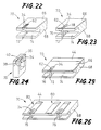
- FIGs. 18-28 there is illustrated a further embodiment of the present invention.
- the process steps of this embodiment are shown in Figs. 18 through 27, while the core slider to be produced is indicated at 78 in Fig. 28.
- a generally elongate rectangular ferrite block 60 consisting of a single crystal of Mn-Zn ferrite, as indicated in Fig. 18.
- This ferrite block 60 has a thickness which is several times that of the ferrite sheet 10 used in the preceding embodiments.
- a plurality of glass-filler grooves 62 are formed in the ferrite block 60, as indicated in Fig. 19, such that the grooves 62 are spaced apart from each other by a spacing distance equal to that of the chip-accommodating grooves 26 in the preceding embodiments.
- the formed glass-filler grooves 62 are filled with the low-melting-point bonding glass mass 34 as used in the preceding embodiments.
- the ferrite block 60 is sliced into a plurality of ferrite sheets 66 each having the same thickness as the ferrite sheet 10.
- One of these ferrite sheets 66 is shown in Fig. 20(a).
- the opposite major surfaces of each ferrite sheet 66 are ground, and one of the ground surfaces is mirror-polished.
- a ceramic sheet 68 which is made of the same non-magnetic material and has the same thickness and cross sectional area as the ceramic sheet 12 used in the preceding embodiments.
- This ceramic sheet 68 which is shown in Fig. 20(b), is ground at the opposite major surfaces, and is mirror-polished at one of the ground surfaces, like the ferrite sheet 66.
- a slider body blank 70 is prepared as indicated in Fig. 21.
- chip-accommodating grooves 72 and a coil-winding groove 74 are formed in the thus prepared slider body blank 70.
- Each chip-accommodating groove 72 is formed through the bonding glass mass 34 filling the glass-filler groove 62. More specifically, a portion of the bonding glass mass 34 is left on the opposite surfaces of the groove 62 such that the remaining portion of the glass mass 34 defines the chip-accommodating groove 72 aligned with the centerline of the groove 62, as indicated in Fig. 22. Namely, the width of the chip-accommodating groove 72 is smaller than that of the glass-filler groove 62.
- a core chip 76 having a magnetic gap 40 is inserted into the appropriate chip-accommodating groove 72.
- the slider body blank 70 is heated to soften the remaining bonding glass mass 34, to thereby bond the chip 76 to the blank 70, as shown in Fig. 23.
- the core chip 76 used in this third embodiment is more or less similar to the core chip 24 of the preceding embodiments, but is different from the core chip 24 in that the narrow portion 38 is formed in the middle of the thickness of the chip 76. Further, the masses of the bonding glass 34 are deposited on the chip 76 such that the narrow portion 36 is embedded in the bonding glass 34.
- the core chip 76 is first positioned in the chip-accommodating groove 72, and the bonding glass 34 is then softened at an elevated temperature, so that the core chip 76 is integrally bonded to the blank 70 with the glass 34, as shown in Fig. 23, like the core chip 24 in the preceding embodiments.
- the surface of the blank 70 in which the magnetic gap 40 of the core chip 76 is open is ground, so as to establish the desired depth of the magnetic gap 40, and the blank 76 is machined to provide the leading ramp 44 at the leading end portion of each air bearing portion 80 on a core slider 78 to be produced (Fig. 28), as shown in Fig. 25.
- the ferrite sheet 66 of the blank 70 is etched to form the air bearing portions 80, as shown in Fig. 26, in the same manner as in the preceding embodiments.
- the blank 70 is trimmed to determine the length of the core slider 78, and chamferred to provide the trailing chamfer, as indicated in Fig. 27.
- the blank 70 is cut to provide the core slider 78 which consists of the core chip 76, and a slider body 82 having the desired width.
- the thickness of the ferrite layers 30 constituting the air bearing portions 80 is preferably not more than 150»m, and more preferably not more than 100»m, in order to effectively avoid the magnetic flux leakage from the core chip 76.
- the core slider 78 produced by the instant third embodiment assures smooth sliding of a magnetic disk (as a data storage medium) on the air bearing portions 80, which are constituted by the Mn-Zn ferrite layers 30 having a low sliding resistance.
- the core slider 78 and the magnetic head including this core slider 78 have considerably increased life expectancy.
- the ferrite layers 30 have an extremely small thickness, and are isolated by the bonding glass 34 from the core chip 76, the instant core slider 78 is substantially free of the deterioration of the magnetic efficiency due to the magnetic flux leakage from the core chip 76.
- the present embodiment is advantageous over the preceding embodiments, since the spacer 42 is not necessary for bonding the core chip 76 to the slider body blank 70.
- the air bearing portions 18, 80 may be formed by machining the slider body blank 16, 70, rather than by etching the blank 16, 70 as in the illustrated embodiments.
- the ferrite sheet 10, 66 may consist of a poly-crystalline Mn-Zn ferrite, and the air bearing portions 18, 80 may be formed by machining either before the blank 16, 70 is ground to define the depth of the magnetic gap 40, or after the blank 16, 70 is ground for the same purpose.
- the core slider 13, 78 has the core chip 24, 76 which is aligned with the centerline of one of the two air bearing portions 18, 80.
- the core chip 24, 76 may be bonded to the slider body 14, 82, at a position intermediate between the two air bearing portions 18, 80 as seen in the direction perpendicular to the direction of extension of the air bearing portions.
Landscapes
- Engineering & Computer Science (AREA)
- Manufacturing & Machinery (AREA)
- Adjustment Of The Magnetic Head Position Track Following On Tapes (AREA)
Claims (16)
- Kerngleitstück (13,78) für ein Magnetfestplattenlaufwerk, mit einem Gleitstückkörper (14,82) mit Lufttragabschnitten (18,80) und einem Kernchip (24,76) mit einem Magnetspalt (40) zum Schreiben und Lesen von Information, der einstückig am Gleitstückkörper befestigt ist, wobei der Gleitstückkörper eine Chipaufnahmenut (26,72) aufweist und der Kernchip (24,76) in der Chipaufnahmenut aufgenommen und mit dem Gleitstückkörper durch Glas fest verbunden ist, wobei das Kerngleitstück dadurch gekennzeichnet ist, daß:
der Kerngleitstückkörper (14,82) einen oder mehrere Ferritteilstücke (30), die zumindest die Lufttragabschnitte (18,80) enthalten und aus Mn-Zn Ferrit gebildet sind, und ein nichtmagnetisches Keramikteilstück (32), das aus einem nichtmagnetischen Keramikmaterial gebildet ist, aufweist. - Kerngleitstück nach Anspruch 1, worin das Ferritteilstück (30) aus einem Einkristall aus Mn-Zn Ferrit besteht.
- Kerngleitstück nach Anspruch 1 oder 2, worin das nichtmagnetische Keramikmaterial des nichtmagnetischen Keramikteilstücks (32) CaTiO₃ als eine Hauptkomponente umfaßt.
- Kerngleitstück nach einem der Ansprüche 1 bis 3, worin das Ferritteilstück (30) eine Dicke von nicht mehr als 150 »m aufweist.
- Kerngleitstück nach einem der Ansprüche 1 bis 4, worin der Kernchip (24,76) einen verjüngten Abschnitt (38) aufweist, der sich in eine Erstreckungsrichtung der Lufttragabschnitte (18,80) erstreckt und den Magnetspalt (40) aufweist, wobei eine Dimension des verjüngten Abschnitts in einer Richtung im rechten Winkel zur Erstreckungsrichtung der Lufttragabschnitte kleiner als eine Dimension der Chipaufnahmenut (26,72) in der genannten Erstreckungsrichtung ist.
- Kerngleitstück nach Anspruch 5, worin der Kernchip (24,76) mit dem Kerngleitstückkörper (14,82) durch ein Glasmaterial verbunden ist, das einen Raum um den verjüngten Abschnitt (38) des Kernchips herum in der Chipaufnahmenut (26,72) ausfüllt.
- Verfahren zur Herstellung eines Kerngleitstücks (13,78) für ein Magnetfestplattenlaufwerk, wobei das Kerngleitstück einen Kerngleitstückkörper (14,82) mit Lufttragabschnitten (18,80) und einen Kernchip (24,76) umfaßt, der einen Magnetspalt (40) zum Schreiben und Lesen von Information aufweist und der einstückig mit dem Kerngleitstückkörper verbunden ist, wobei das Verfahren die folgenden Schritte umfaßt:
das Herstellen eines Kerngleitstückkörperrohlings (16,70), indem ein Mn-Zn Ferritplättchen (10) und ein nichtmagnetisches Keramikplättchen (12) durch Glas miteinander verbunden werden, wobei der Kerngleitstückkörperrohling den Kerngleitstückkörper (14,82) ergibt;
das Herstellen des Kernchips (24,76) mit dem Magnetspalt (40);
das Ausbilden einer Chipaufnahmenut (26,72), um den Kernchip aufzunehmen;
das Einsetzen des Kernchips in die Chipaufnahmenut und das Verbinden des Kernchips mit dem Kerngleitstückkörperrohling durch Glas; und
das Ausbilden der Lufttragabschnitte (18,80) auf dem Kerngleitstückkörperrohling, sodaß die Lufttragabschnitte durch das Mn-Zn Ferritplättchen gebildet werden, um dadurch den Kerngleitstückkörper bereitzustellen. - Verfahren nach Anspruch 7, worin der Schritt des Ausbildens der Lufttragabschnitte (18,80) das Ätzen des Mn-Zn Ferritplättchens (10) des Kerngleitstückkörperrohlings umfaßt.
- Verfahren nach Anspruch 7, worin der Schritt des Ausbildens der Lufttragabschnitte (18,80) das maschinelle Bearbeiten des Mn-Zn Ferritplättchens (10) des Kerngleitstückkörperrohlings umfaßt.
- Verfahren nach einem der Ansprüche 7 bis 9, worin das Kernsubstrat (24) in die Chipaufnahmenut (26) eingesetzt und mit dem Kerngleitstückkörperrohling (16) durch Glas verbunden wird, nachdem die Lufttragabschnitte (18) auf dem Kerngleitstückkörperrohling ausgebildet worden sind.
- Verfahren nach Anspruch 10, weiters umfassend einen Schritt des Schleifens der Lufttragabschnitte (18) und einer Oberfläche des Kernchips (24), in der der Magnetspalt (40) offen ist, nachdem der Kernchip mit dem Kerngleitstückkörperrohling durch Glas verbunden worden ist.
- Verfahren nach einem der Ansprüche 7 bis 9, worin der Kernchip (24) in die Chipaufnahmenut (26,72) eingesetzt und mit dem Kerngleitstückkörperrohling (16) durch Glas verbunden wird, bevor die Lufttragabschnitte (18,80) auf dem Kerngleitstückkörperrohling ausgebildet werden.
- Verfahren nach Anspruch 12, weiters umfassend einen Schritt des Schleifens des Mn-Zn Ferritplättchens (10) und einer Oberfläche des Kernchips (24,76), in der der Magnetspalt (40) offen ist, nachdem der Kernchip mit dem Kerngleitstückkörperrohling durch Glas verbunden worden ist und bevor die Lufttragabschnitte (18,80) gebildet werden.
- Verfahren nach einem der Ansprüche 7 bis 13, weiters einen Schritt des Ausbildens einer Spulenwindungsnut (28,74) im Kerngleitstückkörperrohling (16,70) umfassend, die das Wickeln einer Spule auf dem Kernchip (24,76), der in der Chipaufnahmenut (26,72) aufgenommen ist, ermöglicht.
- Verfahren nach einem der Ansprüche 7 bis 14, worin der Schritt des Verbindens des Kernchips (24) mit dem Kerngleitstückkörperrohling (16) durch Glas das Auffüllen eines Freiraums zwischen dem Kernchip und der Chipaufnahmenut (26) mit einem Verbindungsglas (34) umfaßt.
- Verfahren nach einem der Ansprüche 7 bis 14, weiters einen Schritt des Ausbildens einer Glaseinfüllnut (62) im Kerngleitstückkörperrohling (70) und das Auffüllen der Glaseinfüllnut mit einer Verbindungsglasmasse (34) umfassend, bevor die Chipaufnahmenut (72) durch Entfernen eines Teils der Verbindungsglasmasse gebildet wird, wobei der Kernchip mit dem Kerngleitstückkörper durch einen verbleibenden Teil der Verbindungsglasmasse glas-verbunden wird.
Applications Claiming Priority (2)
| Application Number | Priority Date | Filing Date | Title |
|---|---|---|---|
| JP2074371A JPH0782629B2 (ja) | 1990-03-23 | 1990-03-23 | 固定磁気ディスク装置用コアスライダ及びその製造方法 |
| JP74371/90 | 1990-03-23 |
Publications (3)
| Publication Number | Publication Date |
|---|---|
| EP0449535A2 EP0449535A2 (de) | 1991-10-02 |
| EP0449535A3 EP0449535A3 (en) | 1992-11-25 |
| EP0449535B1 true EP0449535B1 (de) | 1995-06-28 |
Family
ID=13545242
Family Applications (1)
| Application Number | Title | Priority Date | Filing Date |
|---|---|---|---|
| EP91302548A Expired - Lifetime EP0449535B1 (de) | 1990-03-23 | 1991-03-22 | Kerngleitstück für steifen Magnetplattenantrieb und Herstellungsverfahren |
Country Status (4)
| Country | Link |
|---|---|
| US (2) | US5177654A (de) |
| EP (1) | EP0449535B1 (de) |
| JP (1) | JPH0782629B2 (de) |
| DE (1) | DE69110720T2 (de) |
Cited By (1)
| Publication number | Priority date | Publication date | Assignee | Title |
|---|---|---|---|---|
| US7477486B1 (en) | 2005-12-07 | 2009-01-13 | Western Digital (Fremont), Llc | Air bearing slider with a side pad having a shallow recess depth |
Families Citing this family (5)
| Publication number | Priority date | Publication date | Assignee | Title |
|---|---|---|---|---|
| EP0602486B1 (de) * | 1992-12-14 | 1999-02-10 | Minebea Co.,Ltd. | Schwebender Magnetkopf |
| US5522126A (en) * | 1993-03-26 | 1996-06-04 | Ngk Insulators, Ltd. | Method of manufacturing a composite magnetic head |
| US6404591B1 (en) | 1996-02-06 | 2002-06-11 | Mitsumi Electric Co., Ltd. | Magnetic head having cut-out portions for different recording density head cores |
| JP3300970B2 (ja) * | 1996-04-12 | 2002-07-08 | ミネベア株式会社 | 浮動型磁気ヘッドの製造方法 |
| US6445542B1 (en) | 2000-03-06 | 2002-09-03 | Read-Rite Corporation | Air bearing slider |
Family Cites Families (13)
| Publication number | Priority date | Publication date | Assignee | Title |
|---|---|---|---|---|
| JPS5292710A (en) * | 1976-01-30 | 1977-08-04 | Hitachi Ltd | Magnetic head |
| JPS5487516A (en) * | 1977-12-23 | 1979-07-12 | Fujitsu Ltd | Magnetic head |
| FR2447072A1 (fr) * | 1979-01-17 | 1980-08-14 | Cii Honeywell Bull | Corps contenant au moins un transducteur de lecture et/ou d'enregistrement des informations contenues sur un support |
| JPS5622217A (en) * | 1979-08-01 | 1981-03-02 | Hitachi Ltd | Manufacture of magnetic head |
| JPS5625261A (en) * | 1979-08-08 | 1981-03-11 | Fujitsu Ltd | Magnetic head |
| JPS60136004A (ja) * | 1983-12-22 | 1985-07-19 | Fujitsu Ltd | 垂直磁化記録用ヘツドの製造方法 |
| JPS61184708A (ja) * | 1985-02-12 | 1986-08-18 | Hitachi Metals Ltd | 複合型磁気ヘツド |
| JPS61278005A (ja) * | 1985-06-04 | 1986-12-08 | Alps Electric Co Ltd | 浮動式磁気ヘッド |
| JPS62124684A (ja) * | 1985-11-25 | 1987-06-05 | Yokogawa Electric Corp | ヘツドスライダ |
| JPS6334714A (ja) * | 1986-07-29 | 1988-02-15 | Seiko Epson Corp | 浮動型磁気ヘツドの製造方法 |
| JPH01189020A (ja) * | 1988-01-22 | 1989-07-28 | Hitachi Metals Ltd | 浮上型複合磁気ヘッド |
| JPH01276419A (ja) * | 1988-04-27 | 1989-11-07 | Seiko Epson Corp | コンポジット型磁気ヘッドの製造方法 |
| US4870521A (en) * | 1988-06-23 | 1989-09-26 | Kyocera Corporation | Floating magnetic head |
-
1990
- 1990-03-23 JP JP2074371A patent/JPH0782629B2/ja not_active Expired - Lifetime
-
1991
- 1991-03-19 US US07/672,111 patent/US5177654A/en not_active Expired - Fee Related
- 1991-03-22 EP EP91302548A patent/EP0449535B1/de not_active Expired - Lifetime
- 1991-03-22 DE DE69110720T patent/DE69110720T2/de not_active Expired - Fee Related
-
1992
- 1992-08-21 US US07/933,301 patent/US5297330A/en not_active Expired - Fee Related
Cited By (1)
| Publication number | Priority date | Publication date | Assignee | Title |
|---|---|---|---|---|
| US7477486B1 (en) | 2005-12-07 | 2009-01-13 | Western Digital (Fremont), Llc | Air bearing slider with a side pad having a shallow recess depth |
Also Published As
| Publication number | Publication date |
|---|---|
| EP0449535A2 (de) | 1991-10-02 |
| US5177654A (en) | 1993-01-05 |
| JPH0782629B2 (ja) | 1995-09-06 |
| DE69110720D1 (de) | 1995-08-03 |
| DE69110720T2 (de) | 1996-02-08 |
| EP0449535A3 (en) | 1992-11-25 |
| US5297330A (en) | 1994-03-29 |
| JPH03273520A (ja) | 1991-12-04 |
Similar Documents
| Publication | Publication Date | Title |
|---|---|---|
| US5020213A (en) | Method of producing a head core slider | |
| US5107382A (en) | Head core slider having an air bearing surface of a particular configuration | |
| US5157569A (en) | Thin film magnetic head | |
| EP0140977B1 (de) | Magnetkopf und dessen herstellungsverfahren | |
| US4851942A (en) | Floating magnetic head having a magnetic core buried in a channel on an air bearing rail | |
| JPH02156411A (ja) | ディスクドライブシステムに用いられるモノリシィック読出し/書込み記録ヘッドと,その製造方法 | |
| EP0449535B1 (de) | Kerngleitstück für steifen Magnetplattenantrieb und Herstellungsverfahren | |
| KR100320709B1 (ko) | 자기헤드 | |
| EP0356155B1 (de) | Magnetkopf | |
| EP0488539A2 (de) | Herstellungsverfahren für einen fliegenden Magnetkopf | |
| US4821131A (en) | Core assembly for a flying magnetic head with magnetic gap on air-bearing surface | |
| US5010431A (en) | Flying-type composite magnetic head | |
| JP3083675B2 (ja) | 磁気ヘッドの製造方法 | |
| US5016341A (en) | A process for producing magnetic heads of the floating type | |
| US5708543A (en) | Magnetic head with glass used to bond together two core halves having a coefficient of thermal expansion less than that of the ferromagnetic oxide used to make the core halves | |
| US5267107A (en) | Laminated magnetic transducer | |
| JP3057861B2 (ja) | 磁気ヘッドの製造方法 | |
| US5522126A (en) | Method of manufacturing a composite magnetic head | |
| JP3311790B2 (ja) | 複合型磁気ヘッド用コアの製造方法 | |
| JP2545304B2 (ja) | 浮上型磁気ヘッド | |
| JPH0654528B2 (ja) | 磁気ヘツド | |
| JPH08508360A (ja) | 空隙中金属のそして薄膜のハイブリッド読出し/書込みヘッド | |
| JPH03288306A (ja) | マルチチヤンネル磁気ヘツド及びその製造方法 | |
| US20020039255A1 (en) | Magnetic head and method for producing the same | |
| JPH02302907A (ja) | 磁気ヘッド及びその製造方法 |
Legal Events
| Date | Code | Title | Description |
|---|---|---|---|
| PUAI | Public reference made under article 153(3) epc to a published international application that has entered the european phase |
Free format text: ORIGINAL CODE: 0009012 |
|
| 17P | Request for examination filed |
Effective date: 19910507 |
|
| AK | Designated contracting states |
Kind code of ref document: A2 Designated state(s): BE DE FR GB IT LU NL |
|
| PUAL | Search report despatched |
Free format text: ORIGINAL CODE: 0009013 |
|
| AK | Designated contracting states |
Kind code of ref document: A3 Designated state(s): BE DE FR GB IT LU NL |
|
| 17Q | First examination report despatched |
Effective date: 19940818 |
|
| GRAA | (expected) grant |
Free format text: ORIGINAL CODE: 0009210 |
|
| AK | Designated contracting states |
Kind code of ref document: B1 Designated state(s): BE DE FR GB IT LU NL |
|
| REF | Corresponds to: |
Ref document number: 69110720 Country of ref document: DE Date of ref document: 19950803 |
|
| ITF | It: translation for a ep patent filed | ||
| ET | Fr: translation filed | ||
| PG25 | Lapsed in a contracting state [announced via postgrant information from national office to epo] |
Ref country code: LU Free format text: LAPSE BECAUSE OF NON-PAYMENT OF DUE FEES Effective date: 19960331 Ref country code: BE Effective date: 19960331 |
|
| PLBE | No opposition filed within time limit |
Free format text: ORIGINAL CODE: 0009261 |
|
| STAA | Information on the status of an ep patent application or granted ep patent |
Free format text: STATUS: NO OPPOSITION FILED WITHIN TIME LIMIT |
|
| 26N | No opposition filed | ||
| BERE | Be: lapsed |
Owner name: NGK INSULATORS LTD Effective date: 19960331 |
|
| PGFP | Annual fee paid to national office [announced via postgrant information from national office to epo] |
Ref country code: FR Payment date: 19990305 Year of fee payment: 9 |
|
| PGFP | Annual fee paid to national office [announced via postgrant information from national office to epo] |
Ref country code: DE Payment date: 19990308 Year of fee payment: 9 |
|
| PGFP | Annual fee paid to national office [announced via postgrant information from national office to epo] |
Ref country code: NL Payment date: 19990310 Year of fee payment: 9 |
|
| PGFP | Annual fee paid to national office [announced via postgrant information from national office to epo] |
Ref country code: GB Payment date: 19990312 Year of fee payment: 9 |
|
| PG25 | Lapsed in a contracting state [announced via postgrant information from national office to epo] |
Ref country code: GB Free format text: LAPSE BECAUSE OF NON-PAYMENT OF DUE FEES Effective date: 20000322 |
|
| PG25 | Lapsed in a contracting state [announced via postgrant information from national office to epo] |
Ref country code: NL Free format text: LAPSE BECAUSE OF NON-PAYMENT OF DUE FEES Effective date: 20001001 |
|
| GBPC | Gb: european patent ceased through non-payment of renewal fee |
Effective date: 20000322 |
|
| PG25 | Lapsed in a contracting state [announced via postgrant information from national office to epo] |
Ref country code: FR Free format text: LAPSE BECAUSE OF NON-PAYMENT OF DUE FEES Effective date: 20001130 |
|
| NLV4 | Nl: lapsed or anulled due to non-payment of the annual fee |
Effective date: 20001001 |
|
| REG | Reference to a national code |
Ref country code: FR Ref legal event code: ST |
|
| PG25 | Lapsed in a contracting state [announced via postgrant information from national office to epo] |
Ref country code: DE Free format text: LAPSE BECAUSE OF NON-PAYMENT OF DUE FEES Effective date: 20010103 |
|
| PG25 | Lapsed in a contracting state [announced via postgrant information from national office to epo] |
Ref country code: IT Free format text: LAPSE BECAUSE OF NON-PAYMENT OF DUE FEES;WARNING: LAPSES OF ITALIAN PATENTS WITH EFFECTIVE DATE BEFORE 2007 MAY HAVE OCCURRED AT ANY TIME BEFORE 2007. THE CORRECT EFFECTIVE DATE MAY BE DIFFERENT FROM THE ONE RECORDED. Effective date: 20050322 |