EP0449801A2 - Dispositif pour plier des profilés d'écartement creux pour double vitrage - Google Patents
Dispositif pour plier des profilés d'écartement creux pour double vitrage Download PDFInfo
- Publication number
- EP0449801A2 EP0449801A2 EP91890054A EP91890054A EP0449801A2 EP 0449801 A2 EP0449801 A2 EP 0449801A2 EP 91890054 A EP91890054 A EP 91890054A EP 91890054 A EP91890054 A EP 91890054A EP 0449801 A2 EP0449801 A2 EP 0449801A2
- Authority
- EP
- European Patent Office
- Prior art keywords
- hollow profile
- gripper
- bending
- carriage
- slide
- Prior art date
- Legal status (The legal status is an assumption and is not a legal conclusion. Google has not performed a legal analysis and makes no representation as to the accuracy of the status listed.)
- Granted
Links
- 238000005452 bending Methods 0.000 title claims abstract description 35
- 239000011521 glass Substances 0.000 title claims abstract description 5
- 125000006850 spacer group Chemical group 0.000 claims abstract description 12
- 238000000034 method Methods 0.000 description 9
- 230000032258 transport Effects 0.000 description 9
- 239000002184 metal Substances 0.000 description 4
- 238000005259 measurement Methods 0.000 description 2
- 239000002131 composite material Substances 0.000 description 1
- 238000006073 displacement reaction Methods 0.000 description 1
- 239000000428 dust Substances 0.000 description 1
- 230000002349 favourable effect Effects 0.000 description 1
- 239000000463 material Substances 0.000 description 1
- 230000000284 resting effect Effects 0.000 description 1
- 238000011144 upstream manufacturing Methods 0.000 description 1
Images

Classifications
-
- B—PERFORMING OPERATIONS; TRANSPORTING
- B21—MECHANICAL METAL-WORKING WITHOUT ESSENTIALLY REMOVING MATERIAL; PUNCHING METAL
- B21D—WORKING OR PROCESSING OF SHEET METAL OR METAL TUBES, RODS OR PROFILES WITHOUT ESSENTIALLY REMOVING MATERIAL; PUNCHING METAL
- B21D53/00—Making other particular articles
- B21D53/74—Making other particular articles frames for openings, e.g. for windows, doors, handbags
-
- E—FIXED CONSTRUCTIONS
- E06—DOORS, WINDOWS, SHUTTERS, OR ROLLER BLINDS IN GENERAL; LADDERS
- E06B—FIXED OR MOVABLE CLOSURES FOR OPENINGS IN BUILDINGS, VEHICLES, FENCES OR LIKE ENCLOSURES IN GENERAL, e.g. DOORS, WINDOWS, BLINDS, GATES
- E06B3/00—Window sashes, door leaves, or like elements for closing wall or like openings; Layout of fixed or moving closures, e.g. windows in wall or like openings; Features of rigidly-mounted outer frames relating to the mounting of wing frames
- E06B3/66—Units comprising two or more parallel glass or like panes permanently secured together
- E06B3/673—Assembling the units
- E06B3/67304—Preparing rigid spacer members before assembly
- E06B3/67308—Making spacer frames, e.g. by bending or assembling straight sections
- E06B3/67313—Making spacer frames, e.g. by bending or assembling straight sections by bending
-
- E—FIXED CONSTRUCTIONS
- E06—DOORS, WINDOWS, SHUTTERS, OR ROLLER BLINDS IN GENERAL; LADDERS
- E06B—FIXED OR MOVABLE CLOSURES FOR OPENINGS IN BUILDINGS, VEHICLES, FENCES OR LIKE ENCLOSURES IN GENERAL, e.g. DOORS, WINDOWS, BLINDS, GATES
- E06B3/00—Window sashes, door leaves, or like elements for closing wall or like openings; Layout of fixed or moving closures, e.g. windows in wall or like openings; Features of rigidly-mounted outer frames relating to the mounting of wing frames
- E06B3/66—Units comprising two or more parallel glass or like panes permanently secured together
- E06B3/673—Assembling the units
- E06B2003/67395—Non-planar units or of curvilinear outline, e.g. for vehicles
Definitions
- the invention relates to a device for bending hollow profile strips to form spacer frames for insulating glass panes with a bending device and a conveyor for transporting the hollow profile strip.
- Such devices are known for example from DE-GM 87 05 796.4 or DE-OS 32 21 986.
- the length of the profile bar (hollow profile bar) projecting beyond the bending point must be determined so that the spacer frame is obtained with the desired dimensions.
- the known bending devices for producing a spacer for insulating glass determine the length of the profile bar by measuring the distance via incremental encoders.
- the profiled rod is moved by transport rollers resting against it on both sides, at least one of which is driven.
- An impeller encoder wheel
- the encoder wheel which runs along the outer profile wall, detects the extent of the advance of the hollow profile bar.
- CH-PS 638 273 From CH-PS 638 273 a device for pressing insulating bars into metal profiles to be joined together to form a composite profile is known.
- a longitudinal movement of the insulating rod is just as little caused by the jaws as in CH-PS 638 273 a movement of the jaws 26 applied to the insulating rod in the longitudinal direction is mentioned.
- a pair of rollers is provided for moving the hollow profile strip.
- the rollers cannot be moved in the longitudinal direction of the hollow profile bar.
- transport rollers which are not movably mounted in the machine frame in the conveying direction, also serve to advance the hollow profile strip to be moved.
- the object of the invention is to create a device with which the length of the profile, i.e. the extent of the advance of the hollow profile strip, can be measured precisely and without tolerances.
- a Gripper is provided, which can be fixed on the hollow profile bar and which is displaceable parallel to the conveyor by a preselectable distance.
- the hollow profile strip (profile bar) to be bent to the spacer frame is advanced by the gripper exactly before each bending operation by the distance which corresponds to the length of the respective leg of the spacer frame. If the length of the leg is greater than the maximum stroke of the gripper, the profile bar is advanced in two or at most more than two steps.
- the procedure can be such that the first stroke (or the first strokes) correspond to a predetermined length (e.g. the maximum stroke) and the last stroke is adapted to the length of the frame leg.
- a structurally simple embodiment of the device according to the invention is characterized in that the gripper is provided on a carriage which is displaceable on a guide running parallel to the conveying device.
- the extent of the movement of the slide for the gripper and thus the advance of the hollow profile bar can be determined particularly precisely and without great effort if it is provided that the drive motor for the slide has a displacement measuring device, e.g. an incremental encoder is assigned.
- the carriage is coupled to an endless toothed belt driven by the drive motor.
- the drive motor is mounted on the slide and has a pinion which meshes with a toothed rack which is fixedly mounted in the device.
- the method of operation is simplified if a stop which can be lowered under the conveying device is provided at the bending point.
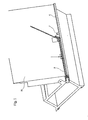
- a hollow profile strip 3 is on a conveyor 4, which is arranged at the lower end of a support wall 10 and is, for example, an endless conveyor belt or a simple slideway, up to a stop 7 in the region of a bending point, consisting of a bending abutment 8 and a bending lever 9, which for the Bending the hollow profile bar 3 is pivoted, transported.
- the device can also have, for example, the structure known from DE-GM 87 05 796 and have a support finger which can be adjusted up and down in the support wall 10 and which extends through the support wall 10, as is also the case in the known device according to DE-GM 87 05 796 is provided.
- the hollow profile bar 3 is from the transport device 4 advanced at the lower edge of the support wall 10 to the end stop 7.
- the hollow profile strip 3 is thus in a "zero" position without tolerance.
- the jaws of the gripper 2 mounted on the slide 1 grip the hollow profile bar 3 in this position.
- the end stop 7 is sunk into the conveyor track 4 and the carriage 1 with the hollow profile bar 3 clamped by the gripper 2 now moves in the direction of the bending lever 9 exactly by the distance that a process computer specifies and that corresponds to the length of the frame leg.
- the bending lever 9 bends the section 3 'projecting beyond the carriage 1' of the hollow profile strip 3, which moves along the backward inclined support wall 10 according to the angle predetermined by a process computer becomes.
- the exact measurement of the distance traveled by the carriage 1 is determined by an incremental encoder 6 or the extent of the movement of the carriage 1 and thus the extent of the advance of the hollow profile strip 3 is controlled by the latter.
- the incremental encoder 6 is mounted on the drive motor 5 or at another point on the movement path 4 of the carriage 1.
- the carriage 1 is driven by an endless toothed belt and is guided on a guide running parallel to the conveyor track 4.
- the engagement of the toothed belt in the drive gear of the drive motor 5 is exact and free of play, so that an incremental encoder 6 mounted directly on the motor-gearbox unit can also accurately register the distance traveled by the slide 1.
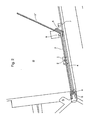
- the effective distance to be traveled by the carriage 1 corresponds to the length of the section 3 'of the hollow profile bar 3, which the process computer determines and the length of a leg of the hollow profile bar 3 to be produced by the bending processes Spacer frame corresponds.
- the drive motor 5 does not need to be fixedly mounted on the bending table 10, but can also be arranged on the slide 1.
- the drive gear of the drive motor 5 (geared motor) then engages in the toothed rack fastened to the guide 4, it being possible for an incremental encoder 6 to also be mounted on the drive motor 5 or on the slide 1.
- the gripper 2 mounted on the slide 1 detaches from the hollow profile bar 3.
- the slide 1 then moves back at high speed into its starting position (reference point), and the gripper 2 is gripped the hollow profile strip 3 again frictionally.
- the carriage 1 can again move in the direction of the bending lever 9 exactly by the distance specified by the process computer and move the hollow profile strip 3 accordingly.
- the conveyor track 4 can be a simple slideway.
- At least one gripper 2 is mounted on the movable carriage 1, which is driven in a slip-free manner by means of a drive means 5 (geared motor), which grips the hollow profile bar 3 in a friction-locked manner.
- the unit slide 1 and gripper 2 transports the hollow profile strip 3 in the direction of the bending lever 9.
- the bending lever 9 presses the section 3 'of the hollow profile bar 3 against the bending abutment 8 (bending beam) as high as from the process computer is determined for the angle in the corner of the spacer frame that is to be bent.
- FIG. 3 A particularly favorable embodiment of a gripper 2, which ensures the necessary frictional engagement for the precise advancement of the hollow profile strip 3, is shown in FIG. 3.
- the movable jaw 12 can be pivoted behind the support wall 10 of the device so that it does not hinder the removal of a finished bent spacer frame.
Landscapes
- Engineering & Computer Science (AREA)
- Civil Engineering (AREA)
- Structural Engineering (AREA)
- Mechanical Engineering (AREA)
- Bending Of Plates, Rods, And Pipes (AREA)
- Securing Of Glass Panes Or The Like (AREA)
- Joining Of Glass To Other Materials (AREA)
Applications Claiming Priority (4)
| Application Number | Priority Date | Filing Date | Title |
|---|---|---|---|
| AT74290A AT398395B (de) | 1990-03-30 | 1990-03-30 | Vorrichtung zum biegen von hohlprofilleisten zu abstandhalterrahmen für isolierglas |
| AT742/90 | 1990-03-30 | ||
| AT1840/90 | 1990-09-10 | ||
| AT184090A AT397775B (de) | 1990-09-10 | 1990-09-10 | Verfahren und vorrichtung zum krümmen von hohlprofilleisten |
Publications (3)
| Publication Number | Publication Date |
|---|---|
| EP0449801A2 true EP0449801A2 (fr) | 1991-10-02 |
| EP0449801A3 EP0449801A3 (en) | 1991-11-06 |
| EP0449801B1 EP0449801B1 (fr) | 1993-11-18 |
Family
ID=25593786
Family Applications (1)
| Application Number | Title | Priority Date | Filing Date |
|---|---|---|---|
| EP91890054A Expired - Lifetime EP0449801B1 (fr) | 1990-03-30 | 1991-03-21 | Dispositif pour plier des profilés d'écartement creux pour double vitrage |
Country Status (7)
| Country | Link |
|---|---|
| US (1) | US5181412A (fr) |
| EP (1) | EP0449801B1 (fr) |
| JP (1) | JPH0724890B2 (fr) |
| DE (2) | DE59100592D1 (fr) |
| DK (1) | DK0449801T3 (fr) |
| ES (1) | ES2046883T3 (fr) |
| NO (1) | NO179683C (fr) |
Cited By (2)
| Publication number | Priority date | Publication date | Assignee | Title |
|---|---|---|---|---|
| WO2020070245A1 (fr) | 2018-10-04 | 2020-04-09 | Lisec Austria Gmbh | Procédé et dispositif de fabrication d'un cadre d'écartement pour verre isolant |
| CN111633081A (zh) * | 2020-06-11 | 2020-09-08 | 郑文豪 | 一种大型钢材折弯设备及折弯工艺 |
Families Citing this family (9)
| Publication number | Priority date | Publication date | Assignee | Title |
|---|---|---|---|---|
| ES2049542T5 (es) * | 1990-06-07 | 1999-06-01 | Peter Lisec | Procedimiento y dispositivo para doblar regletas huecas perfiladas en marcos de separacion para hojas de vidrio aislante. |
| DE59304791D1 (de) * | 1992-07-16 | 1997-01-30 | Peter Lisec | Vorrichtung zum Herstellen von Abstandhalterrahmen für Isolierglasscheiben aus Hohlprofilleisten |
| US6739101B2 (en) * | 2001-01-19 | 2004-05-25 | Cardinal Ig Company | Methods and apparatus for manufacturing muntin bar assemblies |
| US6591988B2 (en) * | 2001-01-19 | 2003-07-15 | Cardinal Glass Industries, Inc. | Material handling for the insulating glass industry |
| WO2003059790A1 (fr) * | 2002-01-15 | 2003-07-24 | Cardinal Ig Company | Procede et appareil pour manipuler des barres fragiles |
| GB2390566A (en) * | 2002-07-09 | 2004-01-14 | Tfx Group Ltd | Improved shaping of thermoplastic tubes |
| CN101590599B (zh) * | 2009-06-19 | 2010-08-25 | 江苏蓝星玻璃有限公司 | 中空铝条折弯机及其折弯方法 |
| US10183363B2 (en) | 2015-08-04 | 2019-01-22 | Cardinal Ig Company | Spacer formation cell |
| CN108356187A (zh) * | 2018-04-17 | 2018-08-03 | 无锡华光锅炉股份有限公司 | 一种钢钉制造装置 |
Family Cites Families (22)
| Publication number | Priority date | Publication date | Assignee | Title |
|---|---|---|---|---|
| US463935A (en) * | 1891-11-24 | Wire-feeding device | ||
| US3299681A (en) * | 1960-03-22 | 1967-01-24 | Baldwin Lima Hamilton Corp | Program controlled tube bender |
| DE1292617B (de) * | 1962-11-30 | 1969-04-17 | Heinrich Bartz Kg | Umrollbiegepresse |
| DE1772812A1 (de) * | 1968-07-08 | 1971-06-09 | Agfa Gevaert Ag | Verfahren zur Herstellung von negativen Halbtonbildern und positiven Halbton- oder Rasterbildern hiervon |
| US3586226A (en) * | 1968-10-03 | 1971-06-22 | Bethlehem Steel Corp | Pulling system for parallel-wire strand |
| US3844461A (en) * | 1973-04-09 | 1974-10-29 | Gerber Scientific Instr Co | Precise indexing apparatus and method |
| US4161110A (en) * | 1977-04-28 | 1979-07-17 | EVG Entwicklungs- und Verwertungs-Gesellschaft mbH. | Automatic control device for a bending machine |
| DE2755669C2 (de) * | 1977-12-14 | 1980-01-31 | Wieland-Werke Ag, 7900 Ulm | Verfahren zur Herstellung eines wärmegedämmten Verbundprofiles und Vorrichtung zur Durchführung des Verfahrens |
| CA1134125A (fr) * | 1978-06-14 | 1982-10-26 | Theo Janssens | Panneaux creux, et dispositif et methode de fabrication connexes |
| US4350033A (en) * | 1979-12-27 | 1982-09-21 | Masamitsu Ishihara | Method and mechanism for constant-measure feed of rod materials |
| JPS5813837U (ja) * | 1981-07-22 | 1983-01-28 | 株式会社日立製作所 | 移動式プレス装置 |
| DE3221986A1 (de) * | 1982-06-11 | 1983-12-15 | Fr. Xaver Bayer Isolierglasfabrik Kg, 7807 Elzach | Maschine zum herstellen eines abstandhaltenden innenrahmens fuer eine isolierglasscheibe |
| IT1175134B (it) * | 1983-10-12 | 1987-07-01 | Piegatrici Macch Elettr | Metodo e mezzi per la realizzazione di sagomati con macchine piegatrici di tondo o filo particolarmente laminato a caldo di basso costo per migliorare la qualita' del prodotto finito |
| JPS60114204A (ja) * | 1983-11-26 | 1985-06-20 | ワイケイケイ株式会社 | スライドフアスナ−の仕上加工におけるグリツパ−装置 |
| US4681210A (en) * | 1984-08-23 | 1987-07-21 | Kabushiki Kaisha Komatsu Seisakusho | Apparatus for feeding bars through a bending or like processing station |
| US4590779A (en) * | 1984-09-18 | 1986-05-27 | Tools For Bending, Inc. | Program-controlled frame bending method and apparatus |
| DE3619643C2 (de) * | 1985-06-22 | 1996-01-11 | Schwarze Rigobert | Rohrbiegemaschine |
| AT401627B (de) * | 1987-03-09 | 1996-10-25 | Lisec Peter | Vorrichtung zum herstellen von abstandhalterrahmen für isolierglasscheiben |
| IT1218985B (it) * | 1988-01-29 | 1990-04-24 | Prima Ind Spa | Sistema per l'ottenimento di segnali di correzione per il comando ed il controllo di un dispositivo manipolatore robotizzato di un impianto di piegatura di lamiere tramite una coppia di elementi sensori posti posteriormente agli elementi di piegatura |
| JPH0651208B2 (ja) * | 1988-07-22 | 1994-07-06 | 石原機械工業株式会社 | 長尺物の連続曲げ加工装置、連続曲げ加工方法およびフープ筋の加工方法 |
| JPH0275419A (ja) * | 1988-09-09 | 1990-03-15 | Chuo Electric Mfg Co Ltd | 曲げ加工装置 |
| DE3924641C1 (fr) * | 1989-07-26 | 1991-02-28 | Aeg-Elotherm Gmbh, 5630 Remscheid, De |
-
1991
- 1991-03-20 NO NO911111A patent/NO179683C/no not_active IP Right Cessation
- 1991-03-21 DE DE91890054T patent/DE59100592D1/de not_active Expired - Fee Related
- 1991-03-21 DK DK91890054.9T patent/DK0449801T3/da not_active Application Discontinuation
- 1991-03-21 EP EP91890054A patent/EP0449801B1/fr not_active Expired - Lifetime
- 1991-03-21 ES ES199191890054T patent/ES2046883T3/es not_active Expired - Lifetime
- 1991-03-22 DE DE4109549A patent/DE4109549C2/de not_active Expired - Fee Related
- 1991-03-27 JP JP3085788A patent/JPH0724890B2/ja not_active Expired - Fee Related
- 1991-03-29 US US07/677,581 patent/US5181412A/en not_active Expired - Lifetime
Cited By (2)
| Publication number | Priority date | Publication date | Assignee | Title |
|---|---|---|---|---|
| WO2020070245A1 (fr) | 2018-10-04 | 2020-04-09 | Lisec Austria Gmbh | Procédé et dispositif de fabrication d'un cadre d'écartement pour verre isolant |
| CN111633081A (zh) * | 2020-06-11 | 2020-09-08 | 郑文豪 | 一种大型钢材折弯设备及折弯工艺 |
Also Published As
| Publication number | Publication date |
|---|---|
| JPH04228234A (ja) | 1992-08-18 |
| DE59100592D1 (de) | 1993-12-23 |
| ES2046883T3 (es) | 1994-02-01 |
| NO179683C (no) | 1996-11-27 |
| EP0449801B1 (fr) | 1993-11-18 |
| US5181412A (en) | 1993-01-26 |
| JPH0724890B2 (ja) | 1995-03-22 |
| EP0449801A3 (en) | 1991-11-06 |
| DK0449801T3 (da) | 1993-12-27 |
| DE4109549A1 (de) | 1991-10-10 |
| NO911111D0 (no) | 1991-03-20 |
| NO179683B (no) | 1996-08-19 |
| NO911111L (no) | 1991-10-01 |
| DE4109549C2 (de) | 1994-01-27 |
Similar Documents
| Publication | Publication Date | Title |
|---|---|---|
| DE3637561C2 (fr) | ||
| DE1777355B2 (de) | Transporteinrichtung zum Transportieren von Werkstücken zwischen zwei Pressen | |
| EP0449801B1 (fr) | Dispositif pour plier des profilés d'écartement creux pour double vitrage | |
| EP0461100B1 (fr) | Procédé et dispositif pour plier des profilés d'écartement creux pour double vitrage | |
| EP0579593B1 (fr) | Dispositif pour la fabrication de cadres d'espacement pour vitres isolantes à partir de profilés d'écartement creux | |
| AT401627B (de) | Vorrichtung zum herstellen von abstandhalterrahmen für isolierglasscheiben | |
| DE2912364C2 (de) | Vorrichtung zum Biegen und Härten oder zum alleinigen Härten von stangenförmigen Werkstücken, insbesondere Blattfedern | |
| EP0240968B1 (fr) | Dispositif pour l'insertion méchanique des joints d'étanchéité | |
| DE3921350C1 (fr) | ||
| DE4116521C2 (de) | Verfahren und Vorrichtung zum Erzeugen gekrümmter Abschnitte in Hohlprofilleisten | |
| EP0349953A2 (fr) | Appareil pour travailler un matériau en forme de profil | |
| DE2152305C3 (de) | Schneidvorrichtung zum Abschneiden eines Rohres | |
| AT397775B (de) | Verfahren und vorrichtung zum krümmen von hohlprofilleisten | |
| AT397055B (de) | Verfahren und vorrichtung zum biegen von hohlprofilleisten zu abstandhalterrahmen für isolierglasscheiben | |
| DE9015527U1 (de) | Vorrichtung zum Biegen von Hohlprofilleisten zu Abstandhalterrahmen für Isolierglas | |
| DE1602460C3 (fr) | ||
| AT405912B (de) | Verfahren und vorrichtung zum krümmen von hohlprofilleisten | |
| DE1928879A1 (de) | Vorrichtung zum Markieren von einer oder mehreren Linien an einem Spantprofil | |
| DE102006059803A1 (de) | Fliegende Kreissäge für ein fortlaufendes querverlaufendes Hochgeschwindigkeitsschneiden von äußerst langen Werkstücken aus Holz | |
| AT401243B (de) | Vorrichtung zum herstellen von abstandhalterrahmen für isolierglasscheiben aus hohlprofilleisten | |
| AT401242B (de) | Vorrichtung zum herstellen von abstandhalterrahmen für isolierglasscheiben aus hohlprofilleisten | |
| DE9016129U1 (de) | Vorrichtung zum Krümmen von Profilleisten | |
| DE170210C (fr) | ||
| DE2060686A1 (de) | Verfahren und Vorrichtung zur Herstellung von Rohrschlangen | |
| EP0416223A1 (fr) | Méthode et dispositif pour cintrer de matières en forme de barre |
Legal Events
| Date | Code | Title | Description |
|---|---|---|---|
| PUAI | Public reference made under article 153(3) epc to a published international application that has entered the european phase |
Free format text: ORIGINAL CODE: 0009012 |
|
| PUAL | Search report despatched |
Free format text: ORIGINAL CODE: 0009013 |
|
| AK | Designated contracting states |
Kind code of ref document: A2 Designated state(s): CH DE DK ES FR GB IT LI SE |
|
| AK | Designated contracting states |
Kind code of ref document: A3 Designated state(s): CH DE DK ES FR GB IT LI SE |
|
| 17P | Request for examination filed |
Effective date: 19911030 |
|
| 17Q | First examination report despatched |
Effective date: 19930406 |
|
| GRAA | (expected) grant |
Free format text: ORIGINAL CODE: 0009210 |
|
| AK | Designated contracting states |
Kind code of ref document: B1 Designated state(s): CH DE DK ES FR GB IT LI SE |
|
| GBT | Gb: translation of ep patent filed (gb section 77(6)(a)/1977) |
Effective date: 19931118 |
|
| REF | Corresponds to: |
Ref document number: 59100592 Country of ref document: DE Date of ref document: 19931223 |
|
| ET | Fr: translation filed | ||
| REG | Reference to a national code |
Ref country code: DK Ref legal event code: T3 |
|
| REG | Reference to a national code |
Ref country code: ES Ref legal event code: FG2A Ref document number: 2046883 Country of ref document: ES Kind code of ref document: T3 |
|
| ITF | It: translation for a ep patent filed | ||
| PLBE | No opposition filed within time limit |
Free format text: ORIGINAL CODE: 0009261 |
|
| STAA | Information on the status of an ep patent application or granted ep patent |
Free format text: STATUS: NO OPPOSITION FILED WITHIN TIME LIMIT |
|
| 26N | No opposition filed | ||
| EAL | Se: european patent in force in sweden |
Ref document number: 91890054.9 |
|
| REG | Reference to a national code |
Ref country code: GB Ref legal event code: IF02 |
|
| PGFP | Annual fee paid to national office [announced via postgrant information from national office to epo] |
Ref country code: SE Payment date: 20030311 Year of fee payment: 13 |
|
| PGFP | Annual fee paid to national office [announced via postgrant information from national office to epo] |
Ref country code: FR Payment date: 20030314 Year of fee payment: 13 |
|
| PGFP | Annual fee paid to national office [announced via postgrant information from national office to epo] |
Ref country code: DK Payment date: 20030410 Year of fee payment: 13 |
|
| PG25 | Lapsed in a contracting state [announced via postgrant information from national office to epo] |
Ref country code: SE Free format text: LAPSE BECAUSE OF NON-PAYMENT OF DUE FEES Effective date: 20040322 |
|
| PG25 | Lapsed in a contracting state [announced via postgrant information from national office to epo] |
Ref country code: DK Free format text: LAPSE BECAUSE OF NON-PAYMENT OF DUE FEES Effective date: 20040331 |
|
| EUG | Se: european patent has lapsed | ||
| PG25 | Lapsed in a contracting state [announced via postgrant information from national office to epo] |
Ref country code: FR Free format text: LAPSE BECAUSE OF NON-PAYMENT OF DUE FEES Effective date: 20041130 |
|
| REG | Reference to a national code |
Ref country code: FR Ref legal event code: ST |
|
| PG25 | Lapsed in a contracting state [announced via postgrant information from national office to epo] |
Ref country code: IT Free format text: LAPSE BECAUSE OF NON-PAYMENT OF DUE FEES;WARNING: LAPSES OF ITALIAN PATENTS WITH EFFECTIVE DATE BEFORE 2007 MAY HAVE OCCURRED AT ANY TIME BEFORE 2007. THE CORRECT EFFECTIVE DATE MAY BE DIFFERENT FROM THE ONE RECORDED. Effective date: 20050321 |
|
| PGFP | Annual fee paid to national office [announced via postgrant information from national office to epo] |
Ref country code: ES Payment date: 20080328 Year of fee payment: 18 |
|
| PGRI | Patent reinstated in contracting state [announced from national office to epo] |
Ref country code: IT Effective date: 20080301 |
|
| PGFP | Annual fee paid to national office [announced via postgrant information from national office to epo] |
Ref country code: DE Payment date: 20080321 Year of fee payment: 18 |
|
| PG25 | Lapsed in a contracting state [announced via postgrant information from national office to epo] |
Ref country code: DE Free format text: LAPSE BECAUSE OF NON-PAYMENT OF DUE FEES Effective date: 20091001 |
|
| PGFP | Annual fee paid to national office [announced via postgrant information from national office to epo] |
Ref country code: CH Payment date: 20100325 Year of fee payment: 20 |
|
| REG | Reference to a national code |
Ref country code: ES Ref legal event code: FD2A Effective date: 20090323 |
|
| PGFP | Annual fee paid to national office [announced via postgrant information from national office to epo] |
Ref country code: IT Payment date: 20100324 Year of fee payment: 20 |
|
| PGFP | Annual fee paid to national office [announced via postgrant information from national office to epo] |
Ref country code: GB Payment date: 20100322 Year of fee payment: 20 |
|
| PG25 | Lapsed in a contracting state [announced via postgrant information from national office to epo] |
Ref country code: ES Free format text: LAPSE BECAUSE OF NON-PAYMENT OF DUE FEES Effective date: 20090323 |
|
| REG | Reference to a national code |
Ref country code: CH Ref legal event code: PL |
|
| REG | Reference to a national code |
Ref country code: GB Ref legal event code: PE20 Expiry date: 20110320 |
|
| PG25 | Lapsed in a contracting state [announced via postgrant information from national office to epo] |
Ref country code: GB Free format text: LAPSE BECAUSE OF EXPIRATION OF PROTECTION Effective date: 20110320 |