EP0450030B1 - Unite electro-acoustique pour la production de hautes intensites soniques et ultra-soniques dans des gaz et des interphases - Google Patents
Unite electro-acoustique pour la production de hautes intensites soniques et ultra-soniques dans des gaz et des interphases Download PDFInfo
- Publication number
- EP0450030B1 EP0450030B1 EP19900915472 EP90915472A EP0450030B1 EP 0450030 B1 EP0450030 B1 EP 0450030B1 EP 19900915472 EP19900915472 EP 19900915472 EP 90915472 A EP90915472 A EP 90915472A EP 0450030 B1 EP0450030 B1 EP 0450030B1
- Authority
- EP
- European Patent Office
- Prior art keywords
- unit according
- electroacoustic unit
- load
- electroacoustic
- power
- Prior art date
- Legal status (The legal status is an assumption and is not a legal conclusion. Google has not performed a legal analysis and makes no representation as to the accuracy of the status listed.)
- Expired - Lifetime
Links
- 230000016507 interphase Effects 0.000 title claims abstract description 4
- 239000007789 gas Substances 0.000 title claims description 8
- 238000006073 displacement reaction Methods 0.000 claims description 11
- 230000005855 radiation Effects 0.000 claims description 8
- 239000007787 solid Substances 0.000 abstract description 3
- 239000007788 liquid Substances 0.000 abstract description 2
- 238000000034 method Methods 0.000 description 4
- 230000005540 biological transmission Effects 0.000 description 3
- 239000003990 capacitor Substances 0.000 description 3
- 238000010586 diagram Methods 0.000 description 3
- 239000000463 material Substances 0.000 description 3
- 238000010276 construction Methods 0.000 description 2
- 230000005284 excitation Effects 0.000 description 2
- 238000010438 heat treatment Methods 0.000 description 2
- 230000009466 transformation Effects 0.000 description 2
- 101000746134 Homo sapiens DNA endonuclease RBBP8 Proteins 0.000 description 1
- 101000969031 Homo sapiens Nuclear protein 1 Proteins 0.000 description 1
- 102100021133 Nuclear protein 1 Human genes 0.000 description 1
- 241000269400 Sirenidae Species 0.000 description 1
- RTAQQCXQSZGOHL-UHFFFAOYSA-N Titanium Chemical compound [Ti] RTAQQCXQSZGOHL-UHFFFAOYSA-N 0.000 description 1
- 230000002745 absorbent Effects 0.000 description 1
- 239000002250 absorbent Substances 0.000 description 1
- 238000010521 absorption reaction Methods 0.000 description 1
- 230000003321 amplification Effects 0.000 description 1
- 230000000712 assembly Effects 0.000 description 1
- 238000000429 assembly Methods 0.000 description 1
- 239000000919 ceramic Substances 0.000 description 1
- 230000008878 coupling Effects 0.000 description 1
- 238000010168 coupling process Methods 0.000 description 1
- 238000005859 coupling reaction Methods 0.000 description 1
- 230000001627 detrimental effect Effects 0.000 description 1
- 230000000694 effects Effects 0.000 description 1
- 238000004519 manufacturing process Methods 0.000 description 1
- 229910052751 metal Inorganic materials 0.000 description 1
- 239000002184 metal Substances 0.000 description 1
- 229910001092 metal group alloy Inorganic materials 0.000 description 1
- 150000002739 metals Chemical class 0.000 description 1
- 238000003199 nucleic acid amplification method Methods 0.000 description 1
- 230000000644 propagated effect Effects 0.000 description 1
- 230000006641 stabilisation Effects 0.000 description 1
- 238000011105 stabilization Methods 0.000 description 1
- 239000010936 titanium Substances 0.000 description 1
- 229910052719 titanium Inorganic materials 0.000 description 1
Images


Classifications
-
- B—PERFORMING OPERATIONS; TRANSPORTING
- B06—GENERATING OR TRANSMITTING MECHANICAL VIBRATIONS IN GENERAL
- B06B—METHODS OR APPARATUS FOR GENERATING OR TRANSMITTING MECHANICAL VIBRATIONS OF INFRASONIC, SONIC, OR ULTRASONIC FREQUENCY, e.g. FOR PERFORMING MECHANICAL WORK IN GENERAL
- B06B1/00—Methods or apparatus for generating mechanical vibrations of infrasonic, sonic, or ultrasonic frequency
- B06B1/02—Methods or apparatus for generating mechanical vibrations of infrasonic, sonic, or ultrasonic frequency making use of electrical energy
- B06B1/0207—Driving circuits
- B06B1/0223—Driving circuits for generating signals continuous in time
- B06B1/0238—Driving circuits for generating signals continuous in time of a single frequency, e.g. a sine-wave
- B06B1/0246—Driving circuits for generating signals continuous in time of a single frequency, e.g. a sine-wave with a feedback signal
- B06B1/0253—Driving circuits for generating signals continuous in time of a single frequency, e.g. a sine-wave with a feedback signal taken directly from the generator circuit
-
- B—PERFORMING OPERATIONS; TRANSPORTING
- B06—GENERATING OR TRANSMITTING MECHANICAL VIBRATIONS IN GENERAL
- B06B—METHODS OR APPARATUS FOR GENERATING OR TRANSMITTING MECHANICAL VIBRATIONS OF INFRASONIC, SONIC, OR ULTRASONIC FREQUENCY, e.g. FOR PERFORMING MECHANICAL WORK IN GENERAL
- B06B3/00—Methods or apparatus specially adapted for transmitting mechanical vibrations of infrasonic, sonic, or ultrasonic frequency
- B06B3/04—Methods or apparatus specially adapted for transmitting mechanical vibrations of infrasonic, sonic, or ultrasonic frequency involving focusing or reflecting
-
- G—PHYSICS
- G10—MUSICAL INSTRUMENTS; ACOUSTICS
- G10K—SOUND-PRODUCING DEVICES; METHODS OR DEVICES FOR PROTECTING AGAINST, OR FOR DAMPING, NOISE OR OTHER ACOUSTIC WAVES IN GENERAL; ACOUSTICS NOT OTHERWISE PROVIDED FOR
- G10K13/00—Cones, diaphragms, or the like, for emitting or receiving sound in general
Definitions
- the object of this patent application is an electroacoustic unit for efficient generating of high acoustic intensities in gas media and in interphases (gas-solid, gas-liquid.)
- Generating high intensity ultrasonic sonic waves in gases involves outstanding difficulties that are basically connected to the low acoustic impedance of the medium (product of the intensity by the propagation velocity) and the high absorption of the same. Therefore, in order to obtain efficient transmitting of acoustic energy a good coupling between the transmitting system and the gas is necessary. Besides, in order to reach high intensities high vibration amplitudes are required and the acoustic beam must be very directional or focalized.
- sonic and ultrasonic generators for use in gases.
- aerodynamic systems such as whistles and sirens, in which the energy is supplied by a stream of gas.
- the acoustic powers reached with these systems may be high, however, the yields that are obtained are generally low.
- Acoustic signals transmitted are complex and have difficulties in reaching ultrasonic frequencies.
- aerodynamic systems have the disadvantage that, along with acoustic radiation, a large amount of gas coming from the transmitter is propagated.
- the present invention refers to an electroacoustic unit that consists of a transducer system and an electronic feed device.
- the radiating element is a flexional type, but it has a structure having a discontinuous profile.
- the vibration amplitude and the radiation phase are modified in such a way that all the vibrating areas directly contribute to the construction of the acoustic field with a configuration that may be predetermined.
- the same radiatingelement it is possible to obtain two different configurations of the acoustic field, in correspondence with the different profile of each one of the surfaces of the same.
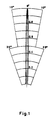
- FIG. 1 shows the directivity diagram of the transducer radiating at its directional surface
- Figure 2 shows the axial and transversal distribution (in the focus) of the acoustic field transmitted by the focalizing surface.
- P represents the acoustic pressure amplitude and D the distance in centimeters.
- Figure 3 shows a transducer System according to the invention
- Figure 4 shows a general block diagram of an electronic generator according to the invention, which includes the transformation, power amplification, generation, automatic frequency control and power control steps.
- the transducer system ( Figure 3) consists essentially of a transducer element (1) that can be piezoelectric or magnetostrictive, a mechanical vibration amplifier (2), which may be exponential, stepped, conical or catenoid, and a radiator which is a plate having a discontinuous profile on the two surfaces (3) thereof.
- the longitudinal vibration generated by the transducer element and amplified by the mechanical amplifier serves to excite the radiating element in one of its flexional modes.
- obtaining directional fields is achieved by displacing alternatively internodal crowns by a half radiation wave length in the medium, for the purpose of putting the entire beam in phase.
- focalized fields are obtained by displacing the internodal crowns in such a way that the distance from the center of said areas to the focal point is such that the radiation arrives in phase said point situated in the field close to the radiator. It is obvious that by varying the length of displacement of the internodal crowns adequately practically any distribution of the acoustic field that is desired can be achieved.
- radiators with a double discontinuous profile aside from the usefulness that is represented by having two configurations of the acoustic field, favors in general lines a more homogeneous distribution of the vibration amplitudes, in comparison with a flat radiator, as a result of the mass distribution. This results in a greater power capacity of the transducer systems which, in the structure that is presented here, is produced by the maximum vibration amplitude which the radiator can develop without breaking.
- the radiators that are presented here must be made out of metals or metal alloys which, like the ones of titanium, have good vibratory features and high mechanical resistance.
- the three basic parts that form it have to be well tuned to the work frequency.
- the system turns out to be highly resonant and, given that the conditions of the medium or by heating the frequency can vary with time, an electronic excitation device with very specific requirements is necessary.
- the generating system aside from producing in each instant a signal whose frequency is situated within a very narrow band (corresponding to the resonance margin of the transmitter used), is capable of automatically correcting the value of said frequency by adapting it to the slipping produced in the resonance band of the transmitter, as the reactive mechanical load associated to the latter varies for different conditions of the radiated medium and of the transmitter device itself.
- the presently used systems for excitation of this type of transducer are based on analogic type oscillator assemblies, formed by a power amplifier refed by the ultrasonic transducer itself by means of a tuned bridge circuit, a phase shifter, a limiter and a band pass filter.
- This type of system has a rather critical performance above all in the initial instants of transmission, also requiring the use of components having a very high precision, as well as including several adjustment points, that have to be adjusted individually for each different ultrasonic transmitter that is connected.
- the generator object of the present patent application introduces a new process for following up the resonance frequency of the transmitter, which does not need the transducer to be introduced in the refeed (feedback) loop of the oscillating circuit.
- the process is based on the fact that a sonic or ultrasonic transmitter of the piezoelectric type has a purely resistive electric impedance when it vibrates in the central point of its resonance band (assuming that there has been a compensation of the reactive component associated with the interelectrodic capacity of the transducer.)
- a considerable reactive component rapidly appears.
- only the voltage and intensity signals in the transducer will have a negative phase displacement at the resonance frequency.
- the generator accomodates the frequency of the signal at the point in which said phase displacement is cancelled so that resonance is produced.
- Sonic and ultrasonic transducers also have considerable resistance variations in terms of the temperature of the ceramics, which changes extensively during operation due to heating.
- the described system also includes a circuit which measures the power delivered by the transducer to the load and which permits stabilization thereof.
- the generating system consists of the following basic components:
Landscapes
- Engineering & Computer Science (AREA)
- Mechanical Engineering (AREA)
- Physics & Mathematics (AREA)
- Acoustics & Sound (AREA)
- Multimedia (AREA)
- Apparatuses For Generation Of Mechanical Vibrations (AREA)
Abstract
Claims (16)
- Unité électroacoustique, pour la génération de hautes intensités soniques et ultrasoniques dans des gaz et des interphases, constituée d'un système électromécanique de transducteur et d'un dispositif électronique pour une génération commandée du signal électrique de puissance, unité électroacoustique comprenant un dispositif de transducteur constitué de trois parties, c-à-d un élément de transducteur, un amplificateur de vibrations mécaniques et une plaque en forme de radiateur présentant un profil discontinu sur chaque face,
unité caractérisée en ce que les trois parties constituant le dispositif de transducteur sont accordées de façon à résonner à la fréquence de fonctionnement et en ce que le générateur électronique est constitué d'un amplificateur de puissance, d'un circuit PLL (Boucle à Blocage de Phase), d'un circuit mesurant la puissance délivrée au transducteur et d'un circuit commandant la puissance. - Unité électroacoustique selon la revendication 1, dans laquelle l'elément de transducteur peut être piézoélectrique ou magnétostrictif et crée des vibrations longitudinales.
- Unité électroacoustique selon les revendications précédentes, dans laquelle la forme de l'amplificateur mécanique est pratiquement exponentielle, étagée, conique ou caténoïde et amplifie les vibrations générées par l'élément de transducteur, excitant le radiateur dans un de ses modes de vibrations en flexion.
- Unité électroacoustique selon les revendications précédentes, dans laquelle l'élément de radiateur est constitué d'une plaque pouvant avoir une quelconque forme géométrique (circulaire, rectangulaire ou carrée) et dont les deux surfaces présentent un profil discontinu qui est obtenu en déplaçant certaines zones internodales dans une direction normale au plan médian de la plaque.
- Unité électroacoustique selon les revendications précédentes, dans laquelle le nombre et la position des zones internodales déplacées ainsi que la hauteur ou la profondeur déplacements dépendent de la configuration du champ acoustique recherché.
- Unité électroacoustique selon les revendications précédentes, dans laquelle deux champs acoustiques peuvent être générés avec une configuration différente pour un seul radiateur selon les deux profils différents sur chacune des surfaces de radiateur.
- Unité électroacoustique selon les revendications précédentes, dans laquelle l'obtention des champs directionnels est obtenue, dans le cas de radiateurs circulaires, par un mise en vibration dans un des modes symétriques par rapport à l'axe, déplaçant, de façon alternée, les couronnes internodales d'une moitié de longueur d'onde de rayonnement dans le milieu.
- Unité électroacoustique selon les revendications précédentes, dans laquelle l'obtention des champs focalisés est obtenue, dans le cas de radiateurs circulaires, par mise en vibration dans un des modes symétriques par rapport à l'axe, déplaçant les couronnes internodales de telle façon que la distance du centre desdites zones au point focal soit telle que le rayonnement arrive en phase sur ledit point situé dans le champ près du radiateur.
- Unité électroacoustique selon les revendications précédentes, dans laquelle le dispositif de génération électronique produit, à chaque instant, un signal dont la fréquence se trouve dans la bande de résonnance du dispositif de transducteur et corrige automatiquement la valeur de ladite fréquence pour l'adapter au glissement pouvant être produit dans la bande de résonnance de l'émetteur.
- Unité électroacoustique selon les revendications précédentes, dans laquelle le genérateur électronique possède un amplificateur de puissance dans lequel le décalage de phase introduit entre les signaux d'entrée et de sortie est nul.
- Unité électroacoustique selon les revendications précédentes, dans laquelle le générateur électronique comprend un canal d'échantillonnage du signal de courant de charge formé d'une résistance montée en série avec la charge de l'amplificateur avec une valeur ne modifiant pas, de façon appréciable, l'impédance de charge, la tension aux bornes de la résistance étant proportionnelle à l'intensité du courant dans la charge.
- Unité électroacoustique selon les revendications précédentes, dans laquelle le générateur électronique prélève un échantillon de la tension de sortie de l'amplificateur de puissance au moyen d'un diviseur de tension pour commander la puissance.
- Unité électroacoustique selon les revendications précédentes, dans laquelle le générateur électronique comprend un circuit PLL (Boucle à Blocage de Phase) comprenant un oscillateur commandé en tension, un multiplicateur à quatre quadrants servant de comparateur de phase et de filtre passe-bas.
- Unité électroacoustique selon les revendications précédentes, dans laquelle l'oscillateur commandé en tension du générateur électronique possède deux sorties, une fournissant une onde carrée alimentant le comparateur de phase et une autre fournissant une onde sinusoïdale alimentant l'amplificataur, sorties qui sont toutes les deux en décalage de phase de π/2 radians, l'autre entrée du comparateur de phase constituant le signal d'échantillonnage du courant de sortie.
- Unite électroacoustique selon les revendications précédentes, dans laquelle le circuit du générateur électronique mesurant la puissance délivrée à la charge est formé d'un multiplicateur à quatre quadrants dont les entrées sont les échantillons de tension et de courant pris à la sortie de l'amplificateur de puissance, le signal produit étant filtré en passe-bas pour obtenir un signal proportionnel à la puissance effective dans la charge.
- Unité électroacoustique selon les revendications précédentes, dans laquelle le circuit du générateur électronique commandant la puissance delivrée à la charge est constitué d'un comparateur et d'un multiplicateur à quatre quadrants fonctionnant comme atténuateur commandé par la tension.
Applications Claiming Priority (3)
| Application Number | Priority Date | Filing Date | Title |
|---|---|---|---|
| ES8903371A ES2017285A6 (es) | 1989-10-06 | 1989-10-06 | Equipo electroacustico para la generacion de altas intensidades sonicas y ultrasonicas en gases e interfases. |
| ES8903371 | 1989-10-06 | ||
| PCT/ES1990/000033 WO1991005331A1 (fr) | 1989-10-06 | 1990-10-03 | Unite electro-acoustique pour la production de hautes intensites soniques et ultra-soniques dans des gaz et des interphases |
Publications (2)
| Publication Number | Publication Date |
|---|---|
| EP0450030A1 EP0450030A1 (fr) | 1991-10-09 |
| EP0450030B1 true EP0450030B1 (fr) | 1994-07-27 |
Family
ID=26154437
Family Applications (1)
| Application Number | Title | Priority Date | Filing Date |
|---|---|---|---|
| EP19900915472 Expired - Lifetime EP0450030B1 (fr) | 1989-10-06 | 1990-10-03 | Unite electro-acoustique pour la production de hautes intensites soniques et ultra-soniques dans des gaz et des interphases |
Country Status (1)
| Country | Link |
|---|---|
| EP (1) | EP0450030B1 (fr) |
Families Citing this family (5)
| Publication number | Priority date | Publication date | Assignee | Title |
|---|---|---|---|---|
| ES2067396B1 (es) * | 1993-03-11 | 1997-11-01 | Consejo Superior Investigacion | Camara acustica multifrecuencia para la aglomeracion y separacion de particulas en suspension en efluentes gaseosos. |
| US5769913A (en) * | 1993-03-11 | 1998-06-23 | Consejo Superior Investigaciones Cientificas | Multifrequency acoustic chamber for the agglomeration and separation of particles suspended in gaseous effluents |
| BE1009377A3 (fr) * | 1995-05-09 | 1997-03-04 | Consejo Superior Investigacion | Procede et dispositif de deshydratation. |
| WO2007012676A1 (fr) * | 2005-07-27 | 2007-02-01 | Consejo Superior De Investigaciones Científicas | Generateur de sons et d'ultrasons haute intensite, destine au demoussage industriel de liquides par voie aerienne |
| CN101751916B (zh) * | 2008-12-12 | 2012-12-19 | 清华大学 | 超声发声器 |
-
1990
- 1990-10-03 EP EP19900915472 patent/EP0450030B1/fr not_active Expired - Lifetime
Also Published As
| Publication number | Publication date |
|---|---|
| EP0450030A1 (fr) | 1991-10-09 |
Similar Documents
| Publication | Publication Date | Title |
|---|---|---|
| US5299175A (en) | Electroacoustic unit for generating high sonic and ultra-sonic intensities in gases and interphases | |
| Ramos-Fernandez et al. | Automatic system for dynamic control of resonance in high power and high Q ultrasonic transducers | |
| CN109416273B (zh) | 用于自动化技术的现场装置的电磁驱动/接收单元 | |
| EP0463735B1 (fr) | Capteur de température à résonateur piézo-électrique | |
| CN109477750A (zh) | 用于确定和/或监测至少一个过程变量的设备 | |
| EP0450030B1 (fr) | Unite electro-acoustique pour la production de hautes intensites soniques et ultra-soniques dans des gaz et des interphases | |
| CN114669436A (zh) | 调频驱动电路、调频驱动方法、驱动装置 | |
| JPS5913930A (ja) | 温度センサ | |
| CA2042575C (fr) | Unite electroacoustique de production de champs sonores et ultrasonores de grande intensite dans les gaz et les phases a deux etats | |
| CN101273402B (zh) | 基于空气的工业液体除泡沫的宏声波发生器 | |
| Gallego-Juárez et al. | Development of industrial models of high-power stepped-plate sonic and ultrasonic transducers for use in fluids | |
| JPH08340597A (ja) | 超音波送受波器 | |
| CA1044374A (fr) | Deflecteur de faisceau de particules chargees | |
| Zaitsev et al. | Hybrid acoustic waves in thin potassium niobate plates | |
| JP3340475B2 (ja) | 超音波溶着装置 | |
| Ieiri et al. | Resonant excitation of a thin waveguide with an elliptical reflector for high-power ultrasound (ELIPS) | |
| Gallego-Juárez | High power ultrasonic transducers for use in gases and interphases | |
| SU1547084A1 (ru) | Устройство дл генерации ультразвуковых импульсов | |
| SU1763515A1 (ru) | Способ направленной кристаллизации расплава и устройство дл его осуществлени | |
| SU845129A1 (ru) | Акустический преобразователь | |
| SU578065A1 (ru) | Устройство дл ультразвуковой хирургии | |
| SU979054A1 (ru) | Устройство дл автоматической стабилизации энергии при ультразвуковой сварке | |
| SU1640627A1 (ru) | Способ определени прочности бетона | |
| Tsujino et al. | Ultrasonic complex vibration welding system using 100 kHz one-dimensional longitudinal-torsional vibration converter | |
| SU1764132A1 (ru) | Генератор на преобразовател х на поверхностных акустических волнах |
Legal Events
| Date | Code | Title | Description |
|---|---|---|---|
| PUAI | Public reference made under article 153(3) epc to a published international application that has entered the european phase |
Free format text: ORIGINAL CODE: 0009012 |
|
| 17P | Request for examination filed |
Effective date: 19910604 |
|
| AK | Designated contracting states |
Kind code of ref document: A1 Designated state(s): AT BE CH DE DK ES FR GB IT LI LU NL SE |
|
| 17Q | First examination report despatched |
Effective date: 19930910 |
|
| GRAA | (expected) grant |
Free format text: ORIGINAL CODE: 0009210 |
|
| AK | Designated contracting states |
Kind code of ref document: B1 Designated state(s): AT BE CH DE DK ES FR GB IT LI LU NL SE |
|
| PG25 | Lapsed in a contracting state [announced via postgrant information from national office to epo] |
Ref country code: ES Free format text: THE PATENT HAS BEEN ANNULLED BY A DECISION OF A NATIONAL AUTHORITY Effective date: 19940727 Ref country code: DK Effective date: 19940727 Ref country code: AT Effective date: 19940727 Ref country code: LI Effective date: 19940727 Ref country code: CH Effective date: 19940727 |
|
| REF | Corresponds to: |
Ref document number: 109297 Country of ref document: AT Date of ref document: 19940815 Kind code of ref document: T |
|
| REF | Corresponds to: |
Ref document number: 69011085 Country of ref document: DE Date of ref document: 19940901 |
|
| ITF | It: translation for a ep patent filed | ||
| PG25 | Lapsed in a contracting state [announced via postgrant information from national office to epo] |
Ref country code: SE Effective date: 19941027 |
|
| PG25 | Lapsed in a contracting state [announced via postgrant information from national office to epo] |
Ref country code: LU Free format text: LAPSE BECAUSE OF NON-PAYMENT OF DUE FEES Effective date: 19941031 |
|
| REG | Reference to a national code |
Ref country code: CH Ref legal event code: PL |
|
| ET | Fr: translation filed | ||
| PLBE | No opposition filed within time limit |
Free format text: ORIGINAL CODE: 0009261 |
|
| STAA | Information on the status of an ep patent application or granted ep patent |
Free format text: STATUS: NO OPPOSITION FILED WITHIN TIME LIMIT |
|
| 26N | No opposition filed | ||
| PGFP | Annual fee paid to national office [announced via postgrant information from national office to epo] |
Ref country code: BE Payment date: 20011009 Year of fee payment: 12 |
|
| PGFP | Annual fee paid to national office [announced via postgrant information from national office to epo] |
Ref country code: NL Payment date: 20011031 Year of fee payment: 12 |
|
| REG | Reference to a national code |
Ref country code: GB Ref legal event code: IF02 |
|
| PG25 | Lapsed in a contracting state [announced via postgrant information from national office to epo] |
Ref country code: BE Free format text: LAPSE BECAUSE OF NON-PAYMENT OF DUE FEES Effective date: 20021031 |
|
| BERE | Be: lapsed |
Owner name: *CONSEJO SUPERIOR DE INVESTIGACIONES CIENTIFICAS Effective date: 20021031 |
|
| PG25 | Lapsed in a contracting state [announced via postgrant information from national office to epo] |
Ref country code: NL Free format text: LAPSE BECAUSE OF NON-PAYMENT OF DUE FEES Effective date: 20030501 |
|
| NLV4 | Nl: lapsed or anulled due to non-payment of the annual fee |
Effective date: 20030501 |
|
| PG25 | Lapsed in a contracting state [announced via postgrant information from national office to epo] |
Ref country code: IT Free format text: LAPSE BECAUSE OF NON-PAYMENT OF DUE FEES Effective date: 20051003 |
|
| PGFP | Annual fee paid to national office [announced via postgrant information from national office to epo] |
Ref country code: DE Payment date: 20081027 Year of fee payment: 19 |
|
| PGFP | Annual fee paid to national office [announced via postgrant information from national office to epo] |
Ref country code: FR Payment date: 20081001 Year of fee payment: 19 |
|
| PGFP | Annual fee paid to national office [announced via postgrant information from national office to epo] |
Ref country code: GB Payment date: 20081008 Year of fee payment: 19 |
|
| REG | Reference to a national code |
Ref country code: FR Ref legal event code: ST Effective date: 20100630 |
|
| PG25 | Lapsed in a contracting state [announced via postgrant information from national office to epo] |
Ref country code: FR Free format text: LAPSE BECAUSE OF NON-PAYMENT OF DUE FEES Effective date: 20091102 Ref country code: DE Free format text: LAPSE BECAUSE OF NON-PAYMENT OF DUE FEES Effective date: 20100501 |
|
| PG25 | Lapsed in a contracting state [announced via postgrant information from national office to epo] |
Ref country code: GB Free format text: LAPSE BECAUSE OF NON-PAYMENT OF DUE FEES Effective date: 20091003 |