EP0450044B1 - Dispositif de miroir amovible utilise a l'interieur de vehicules automobiles - Google Patents
Dispositif de miroir amovible utilise a l'interieur de vehicules automobiles Download PDFInfo
- Publication number
- EP0450044B1 EP0450044B1 EP90916297A EP90916297A EP0450044B1 EP 0450044 B1 EP0450044 B1 EP 0450044B1 EP 90916297 A EP90916297 A EP 90916297A EP 90916297 A EP90916297 A EP 90916297A EP 0450044 B1 EP0450044 B1 EP 0450044B1
- Authority
- EP
- European Patent Office
- Prior art keywords
- mirror
- removable mirror
- outer frame
- fixed outer
- motor vehicle
- Prior art date
- Legal status (The legal status is an assumption and is not a legal conclusion. Google has not performed a legal analysis and makes no representation as to the accuracy of the status listed.)
- Expired - Lifetime
Links
Images


Classifications
-
- B—PERFORMING OPERATIONS; TRANSPORTING
- B60—VEHICLES IN GENERAL
- B60J—WINDOWS, WINDSCREENS, NON-FIXED ROOFS, DOORS, OR SIMILAR DEVICES FOR VEHICLES; REMOVABLE EXTERNAL PROTECTIVE COVERINGS SPECIALLY ADAPTED FOR VEHICLES
- B60J3/00—Antiglare equipment associated with windows or windscreens; Sun visors for vehicles
- B60J3/02—Antiglare equipment associated with windows or windscreens; Sun visors for vehicles adjustable in position
- B60J3/0204—Sun visors
- B60J3/0278—Sun visors structure of the body
- B60J3/0282—Sun visors structure of the body specially adapted for a courtesy mirror
Definitions
- the present invention relates to a removable mirror device for motor vehicle interiors, especially in sun visor structures of motor vehicles as defined in the preamble of claim 1 and of the type shown in the Spanish ES-A-2 008 520.
- the mirror comprises a container body provided with a rotating device allowing for discretional occultation of the reflective surface and built-in electric illumination means supplied from the battery normally equipping motor vehicles.
- Another mirror device for motor vehicle interiors is known from US-A-4 734 831 and comprises a visor for a vehicle including a vanity mirror assembly which is movable from a stored position within a compartment formed in the visor body to a first use position attached to but extended from the visor body.
- the vanity mirror assembly can also be detached from the visor for remote use.
- the mirror is illuminated by one or more lamps.
- a removable mirror device for motor vehicle interiors of the type shown in the Spanish ES-A-2 008 520 is disclosed as characterized by the features of claim 1.
- This feature of the device of the invention i.e., the fact that the device is formed by two mutually independent components, allows one or several of said fixed outer frames to be disposed within the motor vehicle located in those places, further to the passenger side sun visor as is traditional, which, either originally or at the user's discretion, are deemed to be appropriate for discretional use as a housing for the removable mirror.
- the illumination means with which the removable mirror of the device of the invention is provided may operate by alternatively using, through the corresponding switching means, the motor vehicle battery and the dry cells incorporated in said removable mirror as sources of power supply, allows the illumination means to be supplied from the motor vehicle battery when the removable mirror is housed in said fixed outer frame, while when the removable mirror is out of its housing in the fixed outer frame said means are supplied by the dry cells incorporated in the removable mirror itself, without any type of connexion or link between the removable mirror and the housing thereof in the fixed outer frame being necessary.
- the design of the means switching the electric illumination means with which the removable mirror is provided allows the supply of the said illumination means from the motor vehicle battery to be optional, i.e., several fixed outer frames may be installed and only one or several of them or, even, all of them may be connected to the said battery, which will logically depend on the emplacements contemplated for the fixed outer frames and on the possibilities offered by the vehicle structure itself.
- the removable mirror electric illumination means are supplied exclusively from the dry cells incorporated in the mirror itself.
- the fixed outer frame is characterised in that it is one piece, made preferably from plastics materials having mechanical properties appropriate for the contemplated purpose and is formed by an essentially parallelepipedic hollow rectangular receptacle open on one of the larger sides thereof, the front side under conditions of normal use, there being formed on the free edge of said side all around the perimeter thereof a flange of known shape extending externally and perpendicularly to the remaining sides of the parallelepiped forming a dihedron therewith.
- One of the outer surfaces of the L-shaped rocking push means i.e. the surface situated parallelly to the inner surface of the receptable facing the rocking push means when the removable mirror is housed in the fixed outer frame, forms a concave surface having a contour equal or similar to the one formed by the said inner surface of the receptacle, while the other outer surface of the rocking push means is adapted to be urged by hand allowing removal of the removable mirror when it is housed in the fixed outer frame.
- the housing of the removable mirror in the fixed outer frame is defined between the said facing concave surfaces.
- the switching means for supplying the electric illumination means with which the removable mirror is provided and situated in the interior of the receptacle defined by the fixed outer frame are formed by two opposed projections of essentially right parallelepipedic shape or any other appropriate shape for the contemplated purpose, situated a relatively short distance apart. Said projections are provided with the corresponding terminals of appropriate shape and size for electrical connection by members of known technology, to the motor vehicle battery.
- the removable mirror is characterised in that it is formed by a main body of sufficient volume to contain the electric illumination means and a dry battery with sufficient capacity for supplying said illumination means.
- the main body of the removable mirror which is essentially a right parallelepiped open on one of the longer sides thereof, is formed by a base body and by a rear cover, both produced from plastics materials of appropriate mechanical properties, which may be coupled together by the joint action of a sufficient number of engaging tabs and corresponding retaining apertures in the rear cover and the base body respectively.
- the base body is also provided with ventilation apertures of sufficient number and size to maintain the temperature inside the removable mirror at an appropriate level for the correct operation of the components housed therein, as well as mirror retaining supports and the corresponding apertures allowing the snug passage of the switching projections mounted in the fixed outer frame when the removable mirror is located in the housing defined by the fixed outer frame.
- the shorter side surfaces perpendicular to the longitudinal axis of the main body of the removable mirror are preferably provided along the whole length thereof with a surface of convex contour which snugly fits with the corresponding concave contours forming one of the external surfaces of the L-shaped rocking push means and the inner surface of the receptacle defined by the fixed outer frame facing it.
- the mirror is firmly attached to a translucent material which preferably forms a frame for said mirror although both may logically adopt other mutual configurations equally appropriate for the proposed purpose.
- Both the mirror and the translucent material to which it is attached are, in turn, firmly attached, by processes and materials of known technology, to the free edge of the open side of the said main body and defined in the base body.
- the electric illumination means housed in the interior of the main body of the removable mirror are formed by one or several standard incandescent lamps and by discretional switching and electrical connection members of known technology.
- said electrical connection members allow the actuation of the switching projections housed in the fixed outer frame when the removable mirror is located in the housing defined in the fixed outer frame, the said lamps being located relative to the translucent material so as to optimise the external illumination of the immediate environment of the mirror, comprising also an operating member directly associated with the discretional switching member which projects to the exterior and is operatable at will.
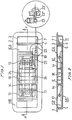
- the removable mirror device for motor vehicle interiors of the invention described here as an embodiment is formed as shown in Figures 1 and 2 of the accompanying sheets of drawings by a fixed outer frame ME and by a removable mirror EA .
- the fixed outer frame ME which is one-piece and preferably made from plastics materials having mechanical properties adequate for the contemplated purpose, is formed by an essentially right parallelepipedical receptacle R which is open on one of the larger sides 1, corresponding to the front side in this embodiment, as shown in Figure 2.
- said receptacle R there is disposed, on the free edge of the sides of the parallelepiped forming a dihedron with the side 1, an outer flange 2 extending around the perimeter projecting over a relative small distance perpendicularly to the said sides, as shown in Figures 1 and 2.
- the outer flange 2 is for concealing the perimeter, produced by mechanical means and usually of irregular contour, of the opening allowing assembly of the fixed outer frame ME in the sun visor structures of motor vehicles or in the structure of other parts of the vehicle passenger compartment, such as doors or seat backrests (not shown in the drawing sheets).
- the retaining and/or ejection means for the removable mirror EA which are disposed in the receptacle R in this embodiment are formed by a rocking push means 3 attached to a transverse shaft 4 extending over the whole length thereof and on which the rocking push means 3 may rock sufficiently in leverlike fashion. Both said members, rocking push means 3 and transverse shaft 4 are situated in one end of the receptacle R with the arrangement shown in Figures 1 and 2.
- the said retaining and/or ejection means also comprise the concave surface forming the inner side wall 5 of the parallelepiped forming the receptacle R which is facing the rocking push means 3 at the opposite end.
- the outer surface 6 of the L-shaped rocking push means 3 which, when the removable mirror EA is housed in the fixed outer frame ME , faces the inner surface 5 of the receptacle R as shown in Figure 2, forms a concave surface having the same profile as the said inner surface 5.
- the outer surface 7 of the L-shaped rocking push means 3 is for hand operation allowing removal of the removable mirror EA from the housing therefor in the receptacle R .
- FIGS. 1 and 2 of the accompanying drawing sheets corresponding to this embodiment being described show in detail how the removable mirror EA is located in the housing therefor in the fixed outer frame ME .
- they are essentially right parallelepipedic in shape and are provided with corresponding terminals 8t which are optionally connected to the motor vehicle battery.
- the removable mirror EA is formed by the main body CP , by the mirror E framed in the perimeter thereof by translucent material and by the electric illumination means IE .
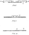
- the main body CP is essentially right parallelepipedic in shape open on one of the larger sides thereof, precisely the one containing the mirror E , and is formed by a base body 9 and by a rear cover 10, as shown in Figures 3 and 4 of the accompanying drawing sheets respectively. Both members forming the main body CP are made preferably from plastics materials having mechanical properties adequate for the contemplated purpose.
- Both members, base body 9 and rear cover 10 may be coupled together by two engagement tabs 11 and the corresponding retaining apertures 12, disposed in the base body 9 and rear cover 10 respectively and which are suitably dimensioned to ensure both a firm coupling together of both said members and, once coupled together, their discretional separation.
- the design of the base body 9 and of the rear cover 10, as shown in detail in Figures 3, 4, 5, 6, 7, 8 and 9, allows access to the interior of the removable mirror EA through the back thereof when both said members are separated, to perform the operations of maintenance and replacement of the unit formed by the components housed therein.
- the base body 9 is also provided with ventilation apertures 13 the number and arrangement whereof, shown in Figures 4 and 7 of this embodiment, ensure that, under normal conditions of use of the device of the invention, the temperature reached within the removable mirror EA will be maintained at appropriate levels for the correct operation of the components housed in the interior thereof.
- the base body 9 is alwo provided with the four supports 14 which, suitably dimensioned and distributed as shown in Figures 2, 4 and 7 of the accompanying drawing sheets, are for preventing possible vibration of the mirror E caused by the motor vehicle when running.
- Figure 4 of this embodiment also shows the two passages 15, disposed in the base body 9, for allowing snug passage therethrough of the corresponding switching projections 8 attached to the respective connexion terminals 8t thereof, disposed in the receptacle R of the fixed outer frame ME , during the insertion and/or removal of the removable mirror EA in or from its housing in the fixed outer frame ME .
- the two outer surfaces 16 of the base body 9 forming the main body CP of the removable mirror EA which are perpendicular to the longitudinal axis of said removable mirror EA , are provided along the whole length thereof, as shown in Figures 2 and 8, with convex surfaces which, respectively, are snugly adapted to the concave surfaces forming the inner surface 5 of the receptacle R and the outer surface 6 of the L-shaped rocking push means 3 situated at one longitudinal end of the fixed outer frame ME .
- the mirror E of known technology, in the embodiment herein described and as shown in Figures 2 and 10, is framed by a continuous strip of translucent material 17 to which it is firmly attached.
- the mirror E and the translucent strip 17 are in turn firmly attached to the main body CP , with both members forming the front surface of the removable mirror EA as shown in detail in Figure 2.
- the inner space of the removable mirror EA which is defined by the main body CP and the mirror E attached to the translucent frame 17, may house the dry cells 18 used as a power source for supplying the electric illumination means IE , which are also housed in the said inner space.
- FIGS 11 and 12 of the accompanying drawing sheets show in detail the constituent members, of the electric illumination means IE of the device of the invention, as well as the interconnexion and operation thereof.
- the two incandescent lamps, 19 contemplated in this embodiment are connected together and with the supply circuit thereto by metal strips 20, 21 and 22 which simultaneously serve as lampholders.
- the two switching projections 8 and corresponding terminals 8t apart from supplying the incandescent lamps 19, perform the following functions: disconnexion of the dry cells 18 from the supply circuit to the said lamps and the connexion of the latter in series to adapt their operating voltage to the voltage supplied by the motor vehicle battery.
- FIG 11 shows in detail how, when the removable mirror EA is not in the housing therefor in the fixed outer frame ME , the two incandescent lamps 19 are supplied through the switch 23 from the dry cells 18 which, as shown in Figures 11 and 12, are connected together in series by the conductors 24.
- the conductor strips 21-22 and 24-25 provide the following functions in view of their resilience: they connect the dry cells 18 to the supply circuit of the two incandescent lamps 19 and connect said lamps in parallel to adapt their operating voltage to the voltage supplied by the dry cells 18 incorporated in the removable mirror EA .
- the operation of the switching projections 8 and the corresponding terminals 8t allows the electric illumination means IE to be supplied with 12 VDC, which is the voltage usually supplied by the battery equipping motor vehicles, when the removable mirror EA is in the housing therefor in the fixed outer frame ME , while, otherwise, i.e. when the removable mirror EA is removed from the housing therefor in the fixed outer frame ME , the illumination means IE are supplied 6 VDC from the dry cells 18 situated in the removable mirror EA .
- 12 VDC is the voltage usually supplied by the battery equipping motor vehicles
- Figure 1 provides a detail thereof, on a larger scale, showing the operating member 23' which is coupled mechanically to said switch 23 by way of the forked pins 23'' and extends to the exterior so that it may be comfortably operated by the user irrespective of whether the removable mirror EA is located in the fixed outer frame ME or not.
- the changes in the voltage supplied to the electric illumination means IE do not imply, under any circumstance whatsoever, a change in the degree of illumination created by the removable mirror EA in the surrounding thereof, since said voltage changes are simultaneously accompanied with the corresponding changes in the interconnexion, in series or in parallel, of the two incandescent lamps 19, whereby the operation voltage of said lamps, which is 6 VDC, remains constant, with the light flux provided by the lamps 19 also remaining constant in this way.
Landscapes
- Engineering & Computer Science (AREA)
- Mechanical Engineering (AREA)
- Rear-View Mirror Devices That Are Mounted On The Exterior Of The Vehicle (AREA)
- Arrangements Of Lighting Devices For Vehicle Interiors, Mounting And Supporting Thereof, Circuits Therefore (AREA)
- Lighting Device Outwards From Vehicle And Optical Signal (AREA)
Claims (10)
- Dispositif de miroir amovible pour montage à l'intérieur des véhicules automobiles, en particulier dans des structures de paresoleil de véhicules automobiles, comprenant une monture extérieure fixe (ME) de dimensions suffisantes pour pouvoir loger, de manière bien ajustée, un miroir (EA), avec des moyens de retenue et/ou d'éjection pour celui-ci, ainsi que des organes de commutation (8,8t) assurant l'alimentation de moyens d'éclairage électriques (IE) dudit miroir (EA), système dans lequel la monture extérieure (ME) est fixée à l'intérieur du véhicule automobile, notamment dans une structure de pare-soleil, le miroir (EA) est retenu de façon amovible dans la monture extérieure (ME) formée par un réceptacle (R),
les moyens d'éclairage électriques (IE) se trouvent derrière le miroir (EA),
le miroir (EA) est fixé à une matière translucide (17) qui l'encadre entièrement ou partiellement,
les moyens d'éclairage électriques (IE) produisent un éclairage diffus aux abords immédiats du miroir amovible (EA),
les moyens d'éclairage électriques (IE) sont alimentés par la batterie du véhicule automobile lorsque le miroir amovible (EA) est logé dans ladite monture extérieure fixe (ME), tandis que ces moyens d'éclairage électriques (IE) sont alimentés par des piles (18) incorporées dans le miroir amovible (EA) proprement dit, quand le miroir amovible (EA) est sorti de son logement ménagé dans la monture extérieure fixe (ME),
dispositif caractérisé en ce que
les piles (18) sont des piles sèches, et en ce que
les moyens de retenue et/ou d'éjection pour le miroir amovible (EA) logé dans la monture extérieure fixe (ME) sont constitués par un poussoir à bascule (3) en forme de L et une surface concave, ce poussoir à bascule (3) en forme de L s'étendant transversalement à l'axe longitudinal de la monture extérieure fixe (ME), et étant rattaché à cette monture (ME) par au moins une tige (4) sur laquelle il peut basculer à la manière d'un levier, la surface concave constituant la surface intérieure (5) de l'extrémité dudit réceptacle (R) située à l'opposé du poussoir à bascule (3) précité. - Dispositif de miroir amovible pour montage à l'intérieur de véhicules automobiles selon la revendication 1, caractérisé en ce que la monture extérieure fixe monobloc (ME) est formée par un réceptacle creux (R) essentiellement parallélépipédique droit, ouvert sur l'un de ses plus grands côtés (1), le côté avant dans des conditions d'utilisation normale, le bord libre dudit côté (1) présentant, sur tout son périmètre, une collerette (2) de forme connue, s'étendant extérieurement et perpendiculairement aux autres côtés du parallélépipède, en formant un dièdre avec le côté (1).
- Dispositif de miroir amovible pour montage à l'intérieur de véhicules automobiles selon les revendications 1 ou 2, caractérisé en ce que la surface extérieure (6) du poussoir à bascule (3) en forme de L, orientée parallèlement à la surface intérieure (5) du réceptacle (R) faisant face au poussoir à bascule (3) lorsque le miroir amovible (EA) se trouve logé dans la monture extérieure fixe (ME), forme une surface concave ayant un contour égal ou similaire à celui formé par ladite surface intérieure (5) du réceptacle (R), tandis que l'autre surface extérieure du poussoir à bascule (3) est adaptée pour pouvoir être poussée à la main, permettant l'enlèvement du miroir amovible (EA) de son logement dans la monture extérieure fixe (ME).
- Dispositif de miroir amovible pour montage à l'intérieur de véhicules automobiles selon les revendications 1 à 3, caractérisé en ce que les organes de commutation (8,8t) assurant l'alimentation des moyens d'éclairage électriques (IE) se trouvant à l'intérieur du réceptacle (R) défini par la monture extérieure fixe (ME), sont constitués par deux saillies opposées (8) de forme essentiellement parallélépipédique droite ou de toute autre forme appropriée en vue de l'utilisation envisagée, espacées d'une distance relativement courte, lesdites saillies (8) étant dotées des bornes correspondantes (8t), de forme et de dimensions appropriées pour assurer la connexion électrique à la batterie du véhicule automobile.
- Dispositif de miroir amovible pour montage à l'intérieur des véhicules automobiles selon les revendications 1 à 4, caractérisé en ce que le miroir amovible (EA) est constitué d'un corps principal (CP) contenant les moyens d'éclairage électriques (IE) et des piles sèches (18) ayant une capacité suffisante pour alimenter lesdits moyens d'éclairage (IE).
- Dispositif de miroir amovible pour montage à l'intérieur des véhicules automobiles selon la revendication 5, caractérisé en ce que le corps principal (CP) comprend un corps de base (9) et un élément de recouvrement arrière (10) susceptibles d'être raccordés par l'action combinée d'un nombre suffisant d'ailettes d'accouplement (22) et de lentes de retenue (12) correspondantes, formées, respectivement, sur l'élément de recouvrement arrière (10) et dans le corps de base (9).
- Dispositif de miroir amovible pour montage à l'intérieur des véhicules automobiles selon la revendication 6, caractérisé en ce que le corps de base (9) est également pourvu de lentes d'aération (13) en nombre et de dimensions suffisant à maintenir la température intérieure du miroir amovible (EA) à un niveau convenable pour le fonctionnement correct des composants qu'il renferme, ainsi que de supports (14) de retenue du miroir (E), et de fentes (15) assurant le passage bien ajusté des saillies de commutation (8) et des bornes correspondantes (8t) logées dans la monture extérieure fixe (ME) lorsque le miroir amovible (EA) se trouve dans le logement ménagé dans la monture extérieure fixe.
- Dispositif de miroir amovible pour montage à l'intérieur des véhicules automobiles selon l'une des revendications 6 ou 7, caractérisé en ce que les deux surfaces (16) perpendiculaires à l'axe longitudinal du corps principal (CP) du miroir amovible (EA) sont pourvues, sur toute leur longueur, d'une surface convexe qui s'adapte de façon bien ajustée aux surfaces concaves correspondantes constituant l'une des surfaces extérieures (6) du poussoir à bascule (3) en forme de L, et la surface intérieure (5) du réceptacle (R) définie par la monture extérieure fixe (ME) lui faisant face.
- Dispositif de miroir amovible pour montage à l'intérieur de véhicules automobiles selon les revendications 6 à 8, caractérisé en ce que le miroir (E) est fermement attaché à une matière translucide (17) qui l'encadre complètement, de préférence, ou partiellement, ces deux éléments, à savoir le miroir (E) et la matière translucide (17), étant fermement attachés au bord libre du côté ouvert du corps principal (CP) constituant le miroir amovible (EA).
- Dispositif de miroir amovible pour montage à l'intérieur de véhicules automobiles selon les revendications 6 à 9, caractérisé en ce que les moyens d'éclairage électriques (IE) logés à l'intérieur du corps principal (CP) du miroir amovible (EA) sont constitués par une ou plusieurs lampes à incandescence (19) et par des organes de commutation (23) et de connexion électrique (20,21,22,24,25) qui, de par leur nature et leur situation à l'intérieur du corps principal (CP), permettent l'actionnement des saillies de commutation (8,8t) logées dans la monture extérieure fixe (ME) lorsque le miroir amovible (EA) se trouve dans son logement ménagé dans ladite monture (ME), lesdites lampes à incandescence (19) étant agencées par rapport à la matière translucide (17) de façon à optimiser l'éclairage extérieur des abords immédiats du miroir (E), et caractérisé par un organe d'actionnement (23') qui fait saillie à l'extérieur et est actionnable à la main, directement associé à l'organe de commutation (23).
Applications Claiming Priority (3)
| Application Number | Priority Date | Filing Date | Title |
|---|---|---|---|
| ES8903609A ES2016755A6 (es) | 1989-10-26 | 1989-10-26 | Dispositivo de espejo amovible para el interior de vehiculos automoviles. |
| ES8903609 | 1989-10-26 | ||
| PCT/ES1990/000039 WO1991006442A1 (fr) | 1989-10-26 | 1990-10-24 | Dispositif de miroir amovible utilise a l'interieur de vehicules automobiles |
Publications (2)
| Publication Number | Publication Date |
|---|---|
| EP0450044A1 EP0450044A1 (fr) | 1991-10-09 |
| EP0450044B1 true EP0450044B1 (fr) | 1996-07-03 |
Family
ID=8264513
Family Applications (1)
| Application Number | Title | Priority Date | Filing Date |
|---|---|---|---|
| EP90916297A Expired - Lifetime EP0450044B1 (fr) | 1989-10-26 | 1990-10-24 | Dispositif de miroir amovible utilise a l'interieur de vehicules automobiles |
Country Status (8)
| Country | Link |
|---|---|
| US (1) | US5274532A (fr) |
| EP (1) | EP0450044B1 (fr) |
| JP (1) | JP2987200B2 (fr) |
| AT (1) | ATE139953T1 (fr) |
| AU (1) | AU7042991A (fr) |
| DE (1) | DE69027667T2 (fr) |
| ES (1) | ES2016755A6 (fr) |
| WO (1) | WO1991006442A1 (fr) |
Families Citing this family (7)
| Publication number | Priority date | Publication date | Assignee | Title |
|---|---|---|---|---|
| DE19519913A1 (de) * | 1995-05-31 | 1996-12-05 | Happich Gmbh Gebr | Sonnenblende für Fahrzeuge |
| GB2332185A (en) * | 1997-12-09 | 1999-06-16 | Rover Group | A motor vehicle sun visor with a detachable light unit |
| AU2001237959A1 (en) * | 2000-01-18 | 2001-07-31 | Prestolite Wire Corporation | Vanity mirror lamp assembly with replaceable battery |
| US6712417B2 (en) | 2001-07-10 | 2004-03-30 | Richard Yurko | Tactical ID visor |
| US7534018B2 (en) * | 2007-03-16 | 2009-05-19 | International Automotive Components North America, Inc. | Illuminated visor vanity |
| US20100225248A1 (en) * | 2009-03-06 | 2010-09-09 | International Automotive Components Group North America, Inc. | Illuminated visor vanity |
| US20170240103A1 (en) | 2016-02-23 | 2017-08-24 | Motus Integrated Technologies | Vehicle sun visor assembly having an electrical system |
Family Cites Families (15)
| Publication number | Priority date | Publication date | Assignee | Title |
|---|---|---|---|---|
| DE274325C (fr) * | ||||
| US2001743A (en) * | 1931-10-22 | 1935-05-21 | Dole Valve Co | Mirror device |
| US2046393A (en) * | 1934-07-05 | 1936-07-07 | Lewinsohn Henry | Illuminated mirror |
| FR1529662A (fr) * | 1967-03-16 | 1968-06-21 | Boîte éclairante | |
| JPS53109254U (fr) * | 1977-02-07 | 1978-09-01 | ||
| DE7921916U1 (de) * | 1979-08-01 | 1979-11-08 | Gebr. Happich Gmbh, 5600 Wuppertal | Sonnenblende fuer fahrzeuge mit einem im sonnenblendenkoerper angeordneten spiegel |
| SE446614B (sv) * | 1983-06-15 | 1986-09-29 | Mekania Verken Ab | Enhet innehallande spegel med belysning |
| US4486819A (en) * | 1983-10-03 | 1984-12-04 | Prince Corporation | Vehicle visor lighting apparatus |
| US4734831A (en) * | 1986-05-28 | 1988-03-29 | Prince Corporation | Visor with concealed removable vanity mirror |
| US4710856A (en) * | 1986-07-07 | 1987-12-01 | Chi Kuan Manufactory Limited | Vanity mirror assembly |
| US4751618A (en) * | 1987-02-12 | 1988-06-14 | Rally Accessories, Inc. | Automatic lighted automobile vanity mirror and lighting circuit therefore |
| DE3727346A1 (de) * | 1987-08-17 | 1989-03-02 | Happich Gmbh Gebr | Beleuchtungseinrichtung fuer fahrzeuge |
| ES2006885A6 (es) * | 1988-04-08 | 1989-05-16 | Gabas Cebollero Carlos | Espejo para visera parasol de automoviles. |
| US4866579A (en) * | 1988-05-23 | 1989-09-12 | Prince Corporation | Snap-in mirror package |
| JPH02127122A (ja) * | 1988-11-08 | 1990-05-15 | Nissan Motor Co Ltd | 自動車用サンバイザー |
-
1989
- 1989-10-26 ES ES8903609A patent/ES2016755A6/es not_active Expired - Lifetime
-
1990
- 1990-10-24 EP EP90916297A patent/EP0450044B1/fr not_active Expired - Lifetime
- 1990-10-24 JP JP2515164A patent/JP2987200B2/ja not_active Expired - Fee Related
- 1990-10-24 AT AT90916297T patent/ATE139953T1/de not_active IP Right Cessation
- 1990-10-24 DE DE69027667T patent/DE69027667T2/de not_active Expired - Fee Related
- 1990-10-24 AU AU70429/91A patent/AU7042991A/en not_active Abandoned
- 1990-10-24 WO PCT/ES1990/000039 patent/WO1991006442A1/fr not_active Ceased
- 1990-10-24 US US07/690,918 patent/US5274532A/en not_active Expired - Lifetime
Also Published As
| Publication number | Publication date |
|---|---|
| ES2016755A6 (es) | 1990-11-16 |
| EP0450044A1 (fr) | 1991-10-09 |
| JPH04502597A (ja) | 1992-05-14 |
| DE69027667T2 (de) | 1997-01-30 |
| DE69027667D1 (de) | 1996-08-08 |
| AU7042991A (en) | 1991-05-31 |
| ATE139953T1 (de) | 1996-07-15 |
| US5274532A (en) | 1993-12-28 |
| JP2987200B2 (ja) | 1999-12-06 |
| WO1991006442A1 (fr) | 1991-05-16 |
Similar Documents
| Publication | Publication Date | Title |
|---|---|---|
| EP0266327B1 (fr) | Pare-soleil pour véhicules automobiles avec miroir illuminé et panneau coulissant | |
| EP0165817A3 (fr) | Assemblage pour l'éclairage | |
| JPH04230439A (ja) | 車内灯兼着脱式フラッシュライト組立品 | |
| EP0450044B1 (fr) | Dispositif de miroir amovible utilise a l'interieur de vehicules automobiles | |
| US6022131A (en) | Room lighting unit for vehicles | |
| EP0846594A3 (fr) | Unité d'éclairage intérieur pour véhicule. | |
| EP0314652B1 (fr) | Paresoleil pour véhicules comportant un miroir éclairé | |
| JPH0986273A (ja) | 車室内照明装置 | |
| EP0340196B1 (fr) | Pare-soleil pour véhicules automobiles | |
| EP0550708A1 (fr) | Dispositif d'eclairage pour miroir de courtoisie de pare-soleil | |
| SE8303424D0 (sv) | Enhet innehallande spegel med belysning | |
| KR200288062Y1 (ko) | 거울이 부착된 자동차용 시트커버 | |
| GB2332185A (en) | A motor vehicle sun visor with a detachable light unit | |
| KR0130581B1 (ko) | 차량 실내등에 장착된 공기 청정 장치 | |
| JPS6154337A (ja) | 自動車用リモコン装置 | |
| KR970002501Y1 (ko) | 자동차 실내등 | |
| KR0119179Y1 (ko) | 자동차용 실내등 | |
| KR19980040199U (ko) | 자동차의 리어시트용 독서등 | |
| KR970046912A (ko) | 차량실내의 독서등겸용 착탈식 손전등 | |
| GB2282691A (en) | Vehicle seat display panel. | |
| KR20050017471A (ko) | 자동차의 재떨이 조명등 구조 | |
| KR19980040787U (ko) | 자동차의 프런트 시트용 조명기구 | |
| JPH0518984U (ja) | マツプランプを兼ねた自動車用ハイマウントストツプランプ | |
| KR19990032336U (ko) | 자동차용 보조실내등 | |
| JP2002114092A (ja) | ルームミラー及び室内灯 |
Legal Events
| Date | Code | Title | Description |
|---|---|---|---|
| PUAI | Public reference made under article 153(3) epc to a published international application that has entered the european phase |
Free format text: ORIGINAL CODE: 0009012 |
|
| AK | Designated contracting states |
Kind code of ref document: A1 Designated state(s): AT BE DE FR GB IT NL SE |
|
| 17P | Request for examination filed |
Effective date: 19910830 |
|
| K1C1 | Correction of patent application (title page) published |
Effective date: 19911009 |
|
| 17Q | First examination report despatched |
Effective date: 19930118 |
|
| RAP1 | Party data changed (applicant data changed or rights of an application transferred) |
Owner name: FICO I.T.M., S.A. |
|
| GRAH | Despatch of communication of intention to grant a patent |
Free format text: ORIGINAL CODE: EPIDOS IGRA |
|
| GRAH | Despatch of communication of intention to grant a patent |
Free format text: ORIGINAL CODE: EPIDOS IGRA |
|
| GRAA | (expected) grant |
Free format text: ORIGINAL CODE: 0009210 |
|
| AK | Designated contracting states |
Kind code of ref document: B1 Designated state(s): AT BE DE FR GB IT NL SE |
|
| PG25 | Lapsed in a contracting state [announced via postgrant information from national office to epo] |
Ref country code: NL Free format text: LAPSE BECAUSE OF FAILURE TO SUBMIT A TRANSLATION OF THE DESCRIPTION OR TO PAY THE FEE WITHIN THE PRESCRIBED TIME-LIMIT Effective date: 19960703 Ref country code: AT Effective date: 19960703 Ref country code: BE Effective date: 19960703 |
|
| REF | Corresponds to: |
Ref document number: 139953 Country of ref document: AT Date of ref document: 19960715 Kind code of ref document: T |
|
| REF | Corresponds to: |
Ref document number: 69027667 Country of ref document: DE Date of ref document: 19960808 |
|
| ITF | It: translation for a ep patent filed | ||
| PG25 | Lapsed in a contracting state [announced via postgrant information from national office to epo] |
Ref country code: SE Effective date: 19961003 |
|
| ET | Fr: translation filed | ||
| ET | Fr: translation filed | ||
| NLV1 | Nl: lapsed or annulled due to failure to fulfill the requirements of art. 29p and 29m of the patents act | ||
| PLBE | No opposition filed within time limit |
Free format text: ORIGINAL CODE: 0009261 |
|
| STAA | Information on the status of an ep patent application or granted ep patent |
Free format text: STATUS: NO OPPOSITION FILED WITHIN TIME LIMIT |
|
| 26N | No opposition filed | ||
| REG | Reference to a national code |
Ref country code: GB Ref legal event code: IF02 |
|
| PGFP | Annual fee paid to national office [announced via postgrant information from national office to epo] |
Ref country code: IT Payment date: 20071025 Year of fee payment: 18 |
|
| PGFP | Annual fee paid to national office [announced via postgrant information from national office to epo] |
Ref country code: FR Payment date: 20071019 Year of fee payment: 18 Ref country code: GB Payment date: 20071016 Year of fee payment: 18 |
|
| PGFP | Annual fee paid to national office [announced via postgrant information from national office to epo] |
Ref country code: DE Payment date: 20071130 Year of fee payment: 18 |
|
| GBPC | Gb: european patent ceased through non-payment of renewal fee |
Effective date: 20081024 |
|
| REG | Reference to a national code |
Ref country code: FR Ref legal event code: ST Effective date: 20090630 |
|
| PG25 | Lapsed in a contracting state [announced via postgrant information from national office to epo] |
Ref country code: IT Free format text: LAPSE BECAUSE OF NON-PAYMENT OF DUE FEES Effective date: 20081024 Ref country code: DE Free format text: LAPSE BECAUSE OF NON-PAYMENT OF DUE FEES Effective date: 20090501 |
|
| PG25 | Lapsed in a contracting state [announced via postgrant information from national office to epo] |
Ref country code: FR Free format text: LAPSE BECAUSE OF NON-PAYMENT OF DUE FEES Effective date: 20081031 |
|
| PG25 | Lapsed in a contracting state [announced via postgrant information from national office to epo] |
Ref country code: GB Free format text: LAPSE BECAUSE OF NON-PAYMENT OF DUE FEES Effective date: 20081024 |